Inserting horizontal loads on columns
The "Horizontal loads" option, available in the "Enter" menu and under "Columns, shear walls and starts", in the "Column input" tab, allows horizontal loads (point, uniform or trapezoidal) to be applied to columns.
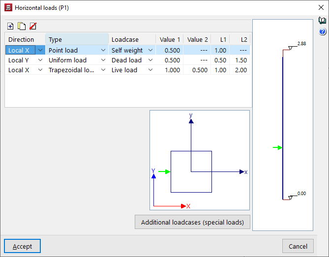
After clicking the option, a column must then be selected. The "Horizontal loads" window will open.
On the right-hand side, an elevation diagram of the column is shown with its initial and final levels. At the bottom, the column cross-section is displayed, together with the global axes of the project and the local axes of the column. The local axes of the column will coincide with the global axes when the column has a zero rotation angle.
In the table at the top, horizontal loads applied to the column segments can be "Added", "Copied" and/or "Deleted". Each row in the table represents a horizontal load applied to the column. For each load, the following parameters are defined:
- Direction
Allows you to select the direction of the horizontal load, either "X Local", "Y Local", "X General" or "Y General". The direction of the load is given by its positive or negative sign. - Type
Allows you to select the type of horizontal load between "Point", "Uniform" or "Trapezoidal". - Loadcase
Allows you to select the loadcase where the horizontal load will act. - Value 1 / Value 2
These parameters allow you to enter the value of the horizontal load with its sign:- If the load is of the "Point" type, only "Value 1" needs to be entered, and the units are force.
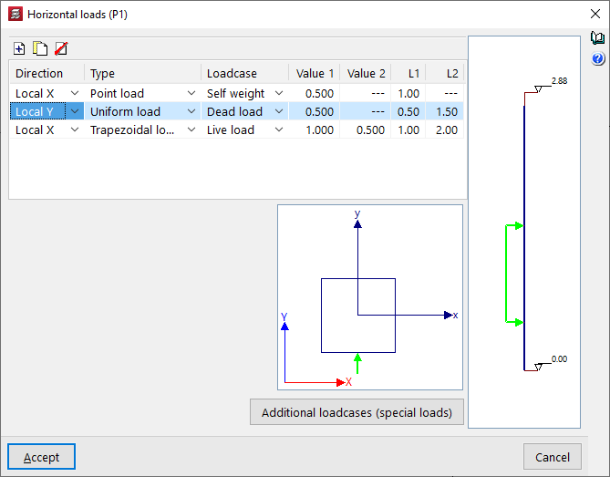
- If the load is of the "Uniform" type, only "Value 1" needs to be entered, which will be applied to the column between the distances defined in "L1" and "L2", and the units are force per unit length.
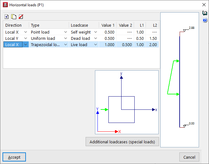
- If the load is of the "Trapezoidal" type, you will need to enter "Value 1" and "Value 2", which will be applied at the distances defined in "L1" and "L2". Between these distances, the load value is interpolated linearly. The units are force per unit length.
- L1 / L2
These parameters define the distance at which the horizontal load is applied:- In the case of a point load, the "L1" value corresponds to the distance between the point of application of the load and the starting point of the column at its bottom.
- In the case of a uniform load or a trapezoidal load, the "L1" value corresponds to the distance between the point of application of the load and the bottom of the column, while the "L2" value corresponds to the distance between the end point of application of the load and the bottom of the column.
The horizontal load selected in the table will be represented both in the elevation diagram on the right and in the section diagram at the bottom.
The "Additional loadcases (special loads)" button at the bottom allows direct access to the panel for creating and editing the loadcases for the structure.