Inserting 'V' bracing
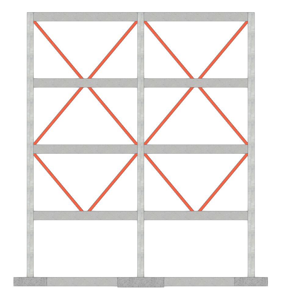
The "Add 'V' bracing" option allows you to insert pairs of V-shaped or inverted V-shaped bracing between two points on the floor plan, formed by steel sections.
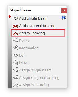
This option is available in the "Sloped beams" menu that appears when you click on the option of the same name in the "Beams" menu, within the "Beam input" tab.
Data on V-shaped bracing
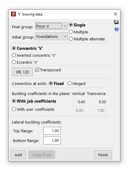
Clicking on the option opens the "V-brace data" window, where the following parameters are configured:
- Final group, Initial group
In the drop-down menus "Final group" and "Initial group", select the groups of plants where the bracing starts and ends. The program does not allow you to select groups in which a grouping of floors has been defined, as it would not be able to determine on which floor the bracing ends or begins. If this is the case, these floors must be ungrouped. On the other hand, it is possible to pass through several intermediate groups of floors. - Single/Multiple
This option is only active if there is a group of plants between the selected final group and the initial group, and allows you to select the input mode:- The "Simple" option enters a single pair of bracing between the selected end group and the start group of floors.
- The "Multiple" option enters several pairs of bracing in several groups at once, located in the same position on the floor plan. This option is only active if there is a group of floors between the selected end group and the selected start group.
- The "Multiple alternate" option enters pairs of bracing in several groups at once, alternating their orientation on each floor.
- Material and section selection
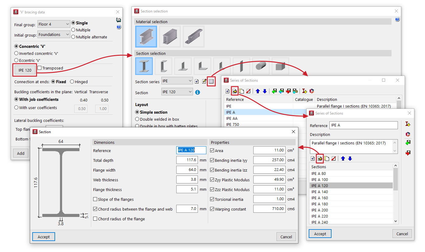
The button on the left opens the "Section selection" window, where you can select the material and section of the steel section from those available, including rolled steel sections, reinforced rolled steel sheet sections, and shaped steel sections.- Transposed
The "Transposed" box allows you to rotate the steel section 90º counterclockwise.
- Transposed
- 'V' type bracing
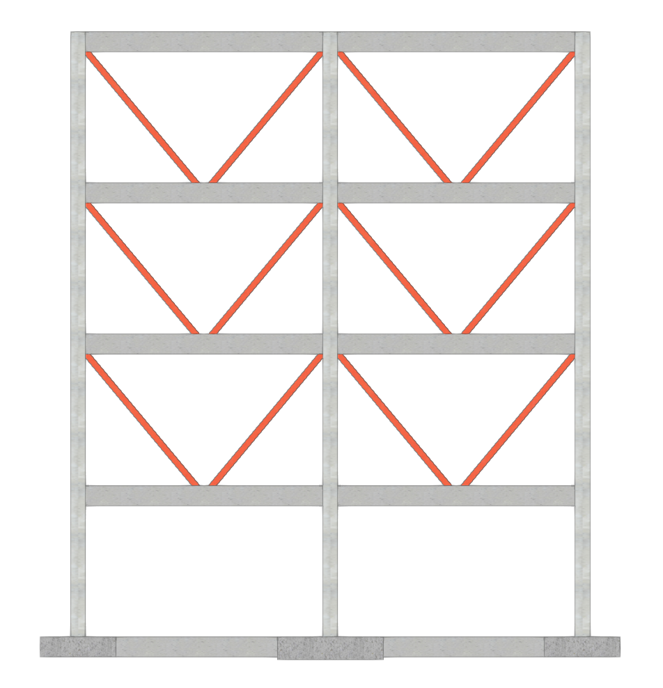
- Concentric V'
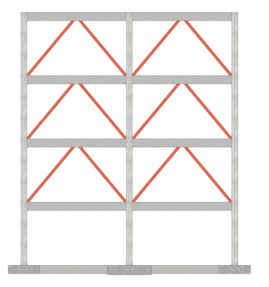
Enters two braces forming a V shape that meet at the central point in the initial group. - Inverted concentric 'V'
Enters two braces, forming an inverted V that joins at the central point in the end group. - Eccentric 'V'
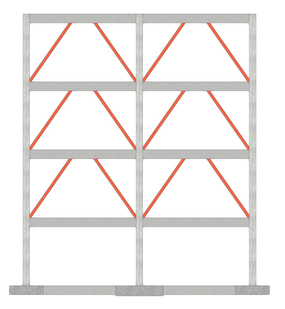
Enters two bracings forming an inverted V and separated by the distance marked in the "Link length" field. This option is only available for "Single" or "Multiple" bracings.
- Concentric V'
- Connection at ends
This can be defined as "Fixed" or "Hinged". - Buckling coefficients in the vertical and transverse planes
This section defines the buckling coefficients in the "Vertical" and "Transverse" planes of the sections that form the bracing. You can select "With project coefficients" (as indicated in "Project > Beam options > Buckling coefficients for sloped steel beams and bracing") or "With own coefficients", in which case the user must enter them. - Lateral buckling coefficients
This section enters the lateral buckling coefficients in the "Top flange" and "Bottom flange" of the sections that form the bracing.
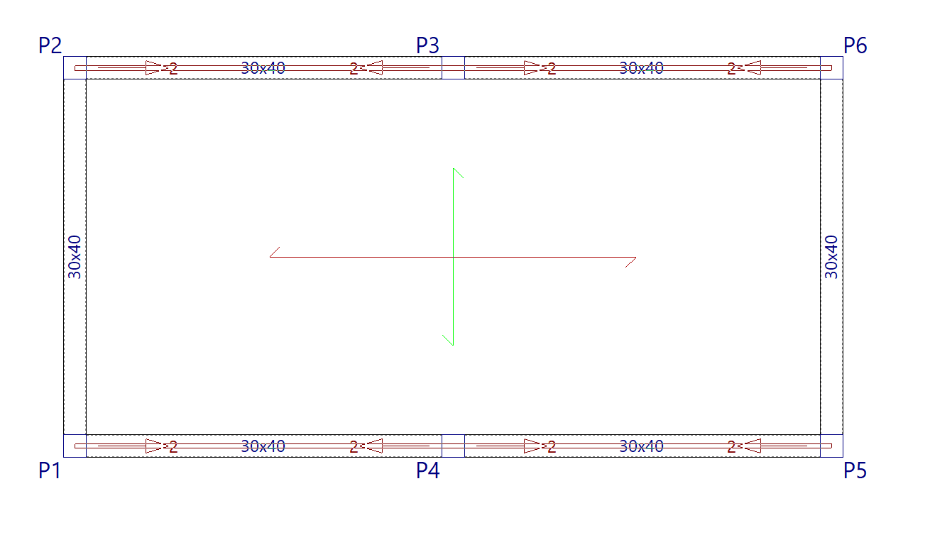
Inserting V-shaped bracing in the floor plan
To insert V-bracing, mark their starting points or their projection in the initial group with the left button. A V-brace can have a column or a horizontal beam as its starting point.
At the central point, the V-shaped bracing must also meet a column or horizontal beam, either in its initial group or in its final group, depending on the type chosen.