
Inserting diagonal bracing
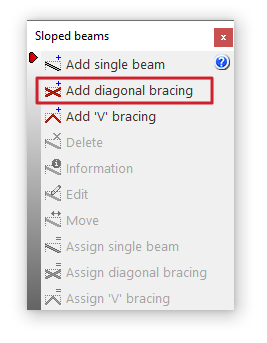
The "Add diagonal bracing" option allows you to enter pairs of bracing diagonals between two points on the floor plan formed by metal profiles.
This option is available in the "Sloped beams" menu that appears when you click on the option of the same name in the "Beams" menu, within the "Beam input" tab.
Diagonal bracing data
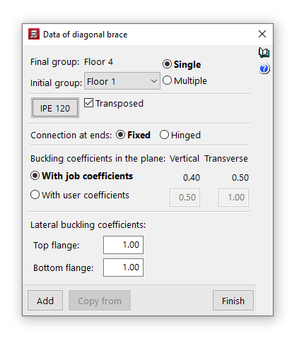
Clicking on the option opens the "Diagonal bracing data" window, where the following parameters are configured:
- Final group, Initial group
In the drop-down menus "Final group" and "Initial group", select the groups of floors where the bracing diagonals start and end. The program does not allow you to select groups in which a grouping of floors has been defined, as it would not be able to determine on which floor the diagonals end or start. If this is the case, these floors must be ungrouped. On the other hand, it is possible to pass through several intermediate groups of floors. - Single/Multiple
This option is only active if there is a group of plants between the selected final group and initial group, and allows you to select the input mode:- The "Simple" option allows you to enter a single pair of diagonal bracing between the selected end group and initial group of floors.
- The "Multiple" option allows you to enter several pairs of diagonal bracing members in several groups at once, located in the same position on the floor plan.
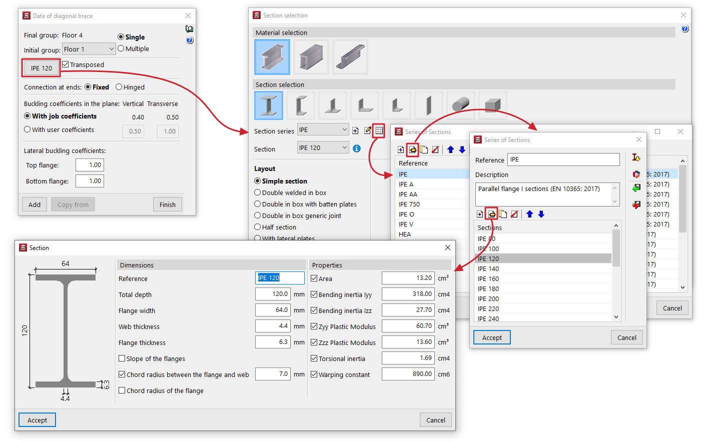
- Material and profile selection
The button on the left opens the "Profile selection" window, where you can select the material and section of the metal profile from those available, including rolled steel profiles, reinforced rolled steel sheet profiles, and shaped steel profiles.- Transposed
The "Transposed" box allows you to rotate the metal profile 90º counterclockwise.
- Transposed
- Connection at the ends
This can be defined as "Bi-potentiometer" or "Bi-articulated". - Buckling coefficients in the vertical and transverse planes
This section allows you to define the buckling coefficients in the "Vertical" and "Transverse" planes of the profiles that form the bracing diagonals. You can select "With project coefficients" (as indicated in "Project > Beam options > Buckling coefficients for inclined steel beams and bracing") or "With own coefficients", in which case the user must enter them. - Lateral buckling coefficients
This section allows you to enter the lateral buckling coefficients in the "Upper wing" and "Lower wing" of the profiles that form the bracing diagonals.
| Nota: |
|---|
| En el caso de diagonales de arriostramiento metálicas, de cara a la obtención de la longitud de pandeo de cada diagonal de arriostramiento, se considera que los coeficientes de pandeo que se piden multiplican a la longitud entre nudos extremos de la diagonal, es decir, no se tiene en cuenta el nudo intermedio que el programa genera en el cruce de barras a estos efectos. Los coeficientes de pandeo vertical y transversal se establecen, respectivamente, en un plano vertical que contiene a la barra y al eje Z de la estructura, y en el transversal a éste, y no según los ejes locales de la barra. |
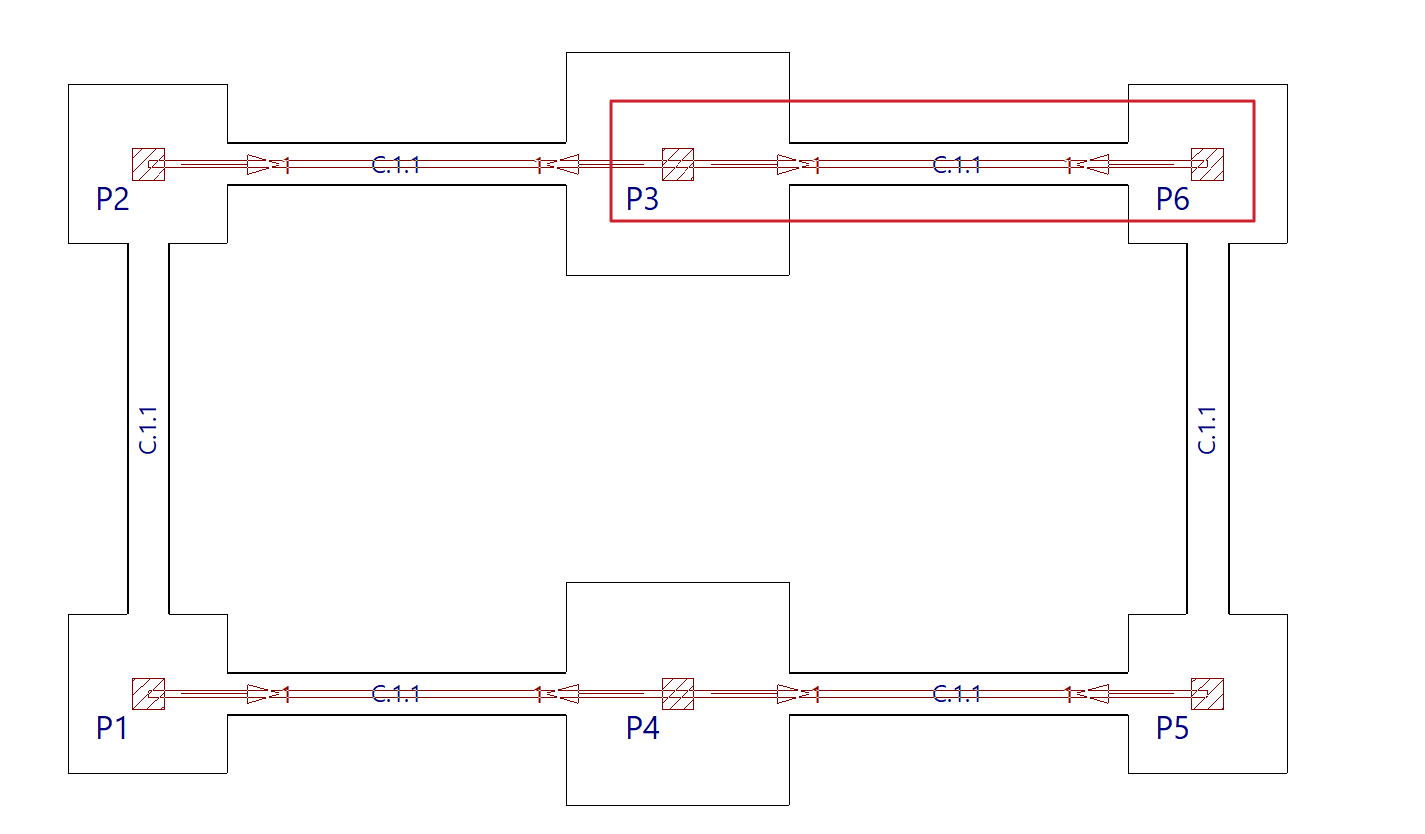
Introducción de las diagonales de arriostramiento en planta
Para introducir las diagonales de arriostramiento, se debe marcar con el botón izquierdo los puntos iniciales de cada una de las diagonales en el grupo inicial.
Una diagonal de arriostramiento puede tener como punto inicial un pilar, por lo que se deben marcar los pies de los pilares en el grupo inicial de las diagonales.
| Nota: |
|---|
| En la intersección de las diagonales de arriostramiento, el programa generará un nudo rígido. Las diagonales se dimensionan tanto a tracción como a compresión. Por ello, pueden presentar problemas de esbeltez, ya que se comprobará que no se supera la esbeltez máxima definida en la normativa correspondiente para elementos sometidos a compresión. |
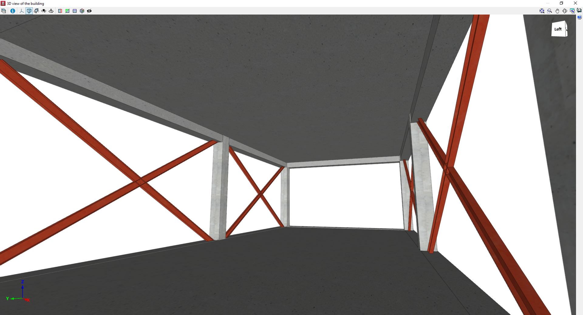
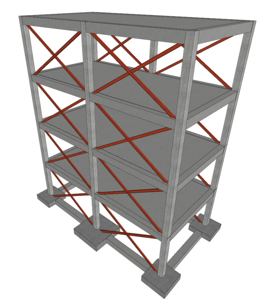
Vistas 3D de un modelo con diagonales de arriostramiento