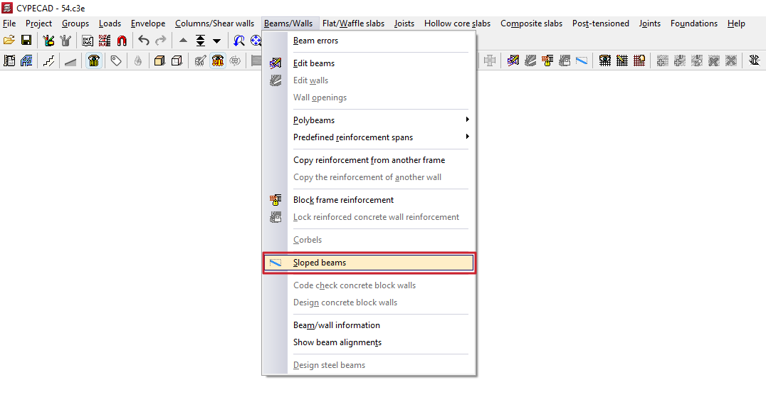
Options in the "Sloped beams" menu (the "Results" tab)
The "Sloped beams" option, within the "Beams" menu on the "Results" tab, allows you to view the analysis results for inclined beams, bracing diagonals and V-bracing.
This option is available if the job has been analysed.
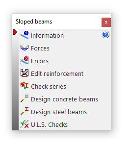
Clicking on this option opens the "Sloped beams" window, which contains a menu with the following tools:
- Information
- Forces
- Errors
- Edit reinforcement
- Check series
- Design concrete beams
- Design steel beams
- U.L.S. checks
Each of these features is described below:
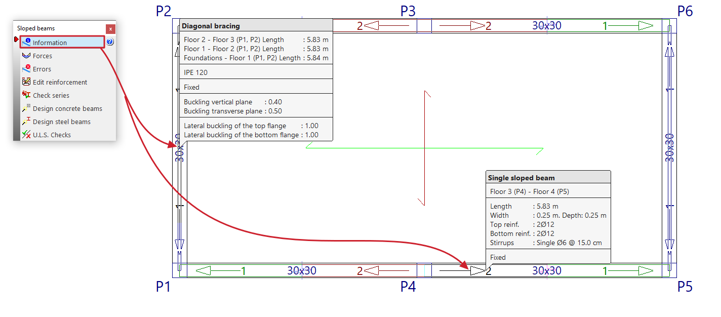
Information
Clicking the "Information" option displays information on screen about the sloped beams, bracing diagonals or V-bracing already entered. To do this, select the element you wish to view on the floor plan using the left mouse button, or enter the corresponding element number.
An information text box then appears, displaying details such as the element’s start and end tags, its length, section, and the other parameters entered in its editing panel.
If the structure has been structurally analysed, information on the bracing of single inclined beams is also included (“Upper bracing”, “Lower bracing” and “Strut bracing”).
This option is the same as the one available in the menu of the same name on the "Beam Input" tab.
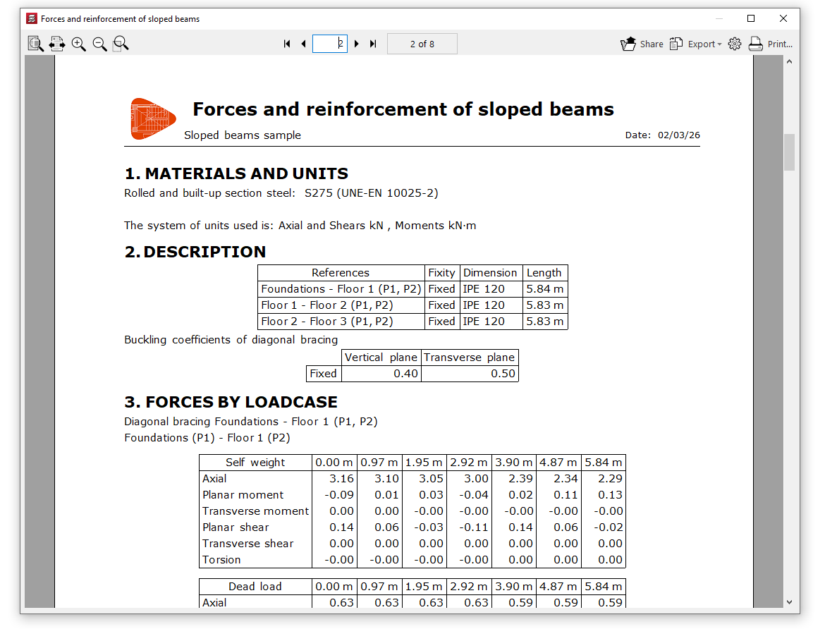
Forces
The "Forces" option provides a list of efforts and results for the selected item.
The forces that can be listed include the "Axial force", the "Planar moment", the "Transverse moment", the "Planar shear", the "Transverse shear" and the "Torsion". To do this, you can tick the boxes with these names.
These results can be obtained for the "Number of points" of the beam entered in the corresponding field.
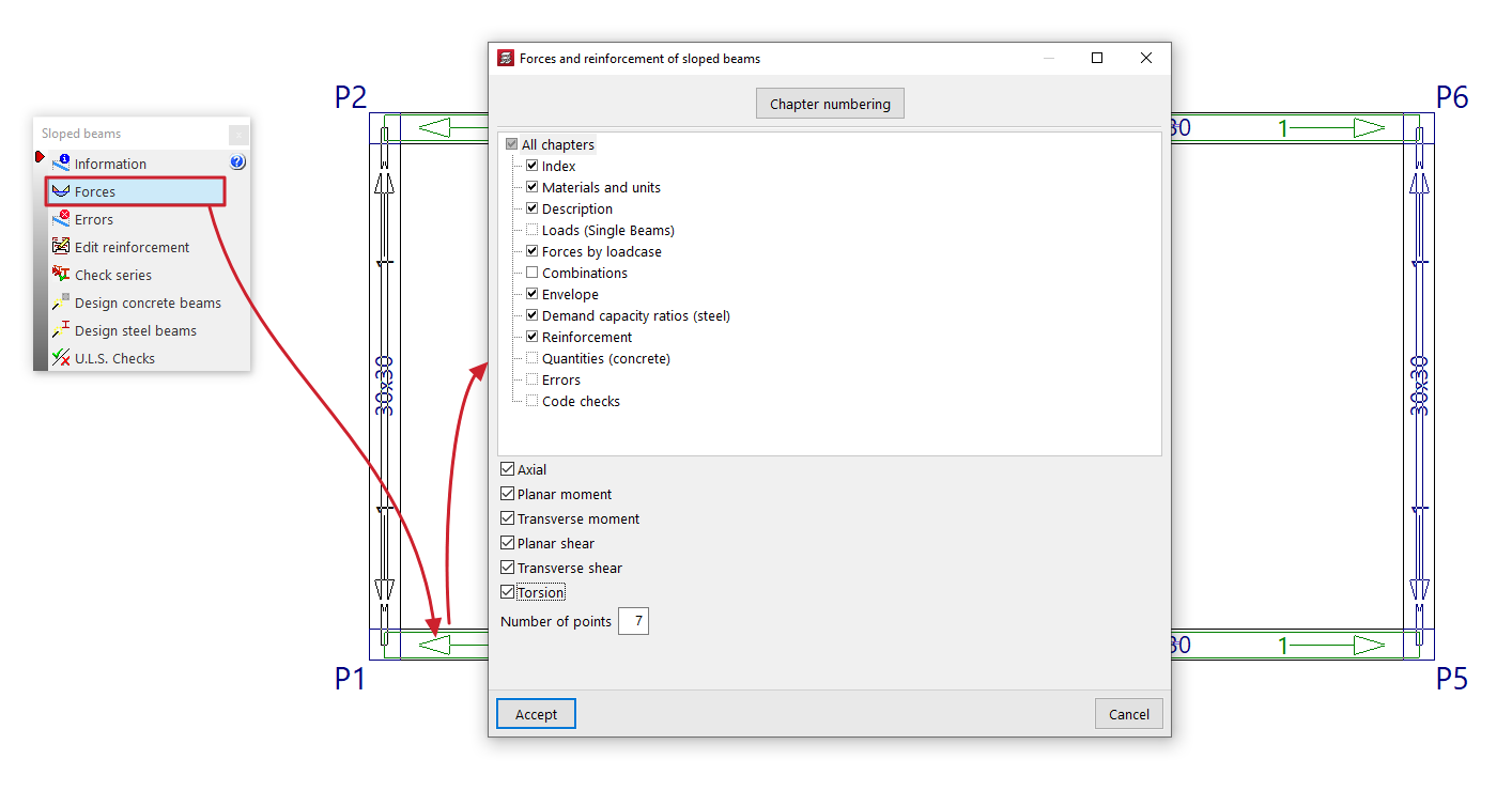
This list includes the materials, description, loads (for simple sloped beams), design forces, combination forces, force envelopes, demand capacity ratio (for steel sections), design results (or reinforcement results in the case of concrete beams), quantities (for concrete beams), design errors where applicable, and checks carried out.
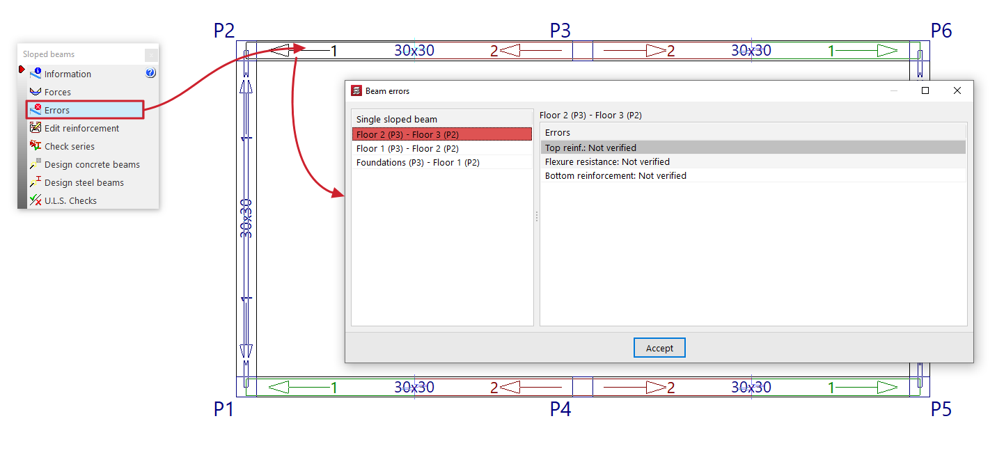
Errors
Sloped beams, bracing diagonals and V-bracing with analysis errors will be highlighted in red in the workspace.
The "Errors" option in this menu allows you to select one of these elements and display a list of errors on screen.
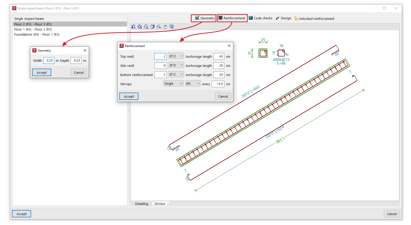
Edit reinforcement
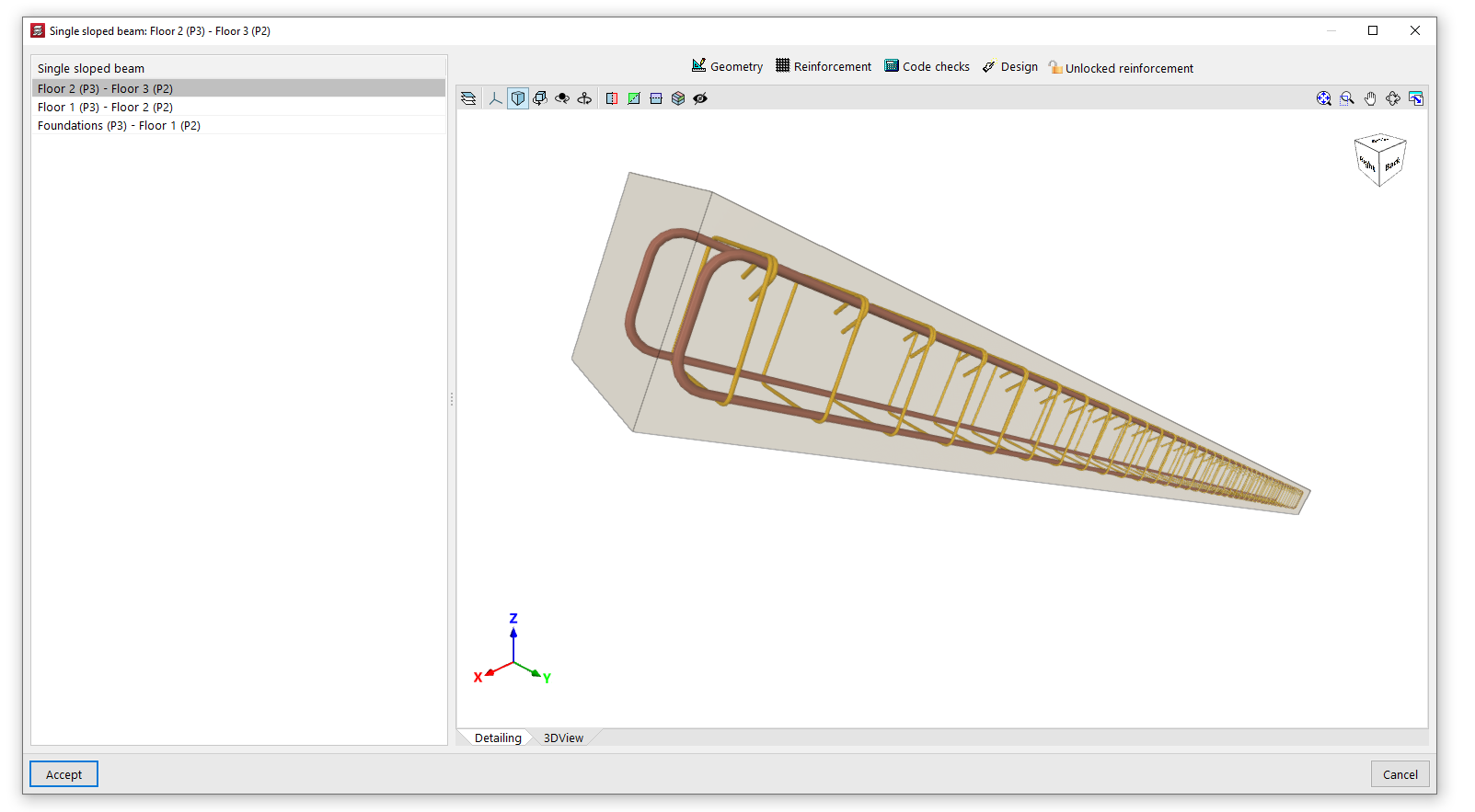
The "Edit reinforcement" option allows you to select a single sloped reinforced concrete beam and view and edit the reinforcement results from the analysis in an editing window.
This editing window has two tabs. The "Section" tab displays a view showing the longitudinal and cross-sectional views of the beam, indicating its dimensions and reinforcement, whilst the "3D View" tab provides a three-dimensional view of the beam with its reinforcement.
In addition, the program provides the following tools at the top of this window:
- Geometry
Allows you to modify the width and depth of the beam. Once modified, you can use the "Dimensioning" option to generate the reinforcement. - Reinforcement
Allows you to modify the number and diameter of the bars in the "Top reinforcement", the "Skin reinforcement" and the "Bottom reinforcement", as well as the type, diameter and spacing of the beam's "Stirrups". You can also modify the "Anchorage length" of the bars in each of the aforementioned reinforcement groups. Once modified, you can use the "Code checks" option to check the beam with the specified reinforcement. - Verification
This allows you to verify compliance with regulatory specifications in light of the changes made. Furthermore, you can display a list of these verifications on screen. - Structural analysis
Carries out a structural analysis of the beam to determine a reinforcement scheme that satisfies all the checks for the beam’s geometry and forces obtained in the analysis. - Locked reinforcement / Unlocked reinforcement
Allows you to lock the beam reinforcement so that the program does not modify it during the analysis and design process, or to unlock it if it has previously been locked.
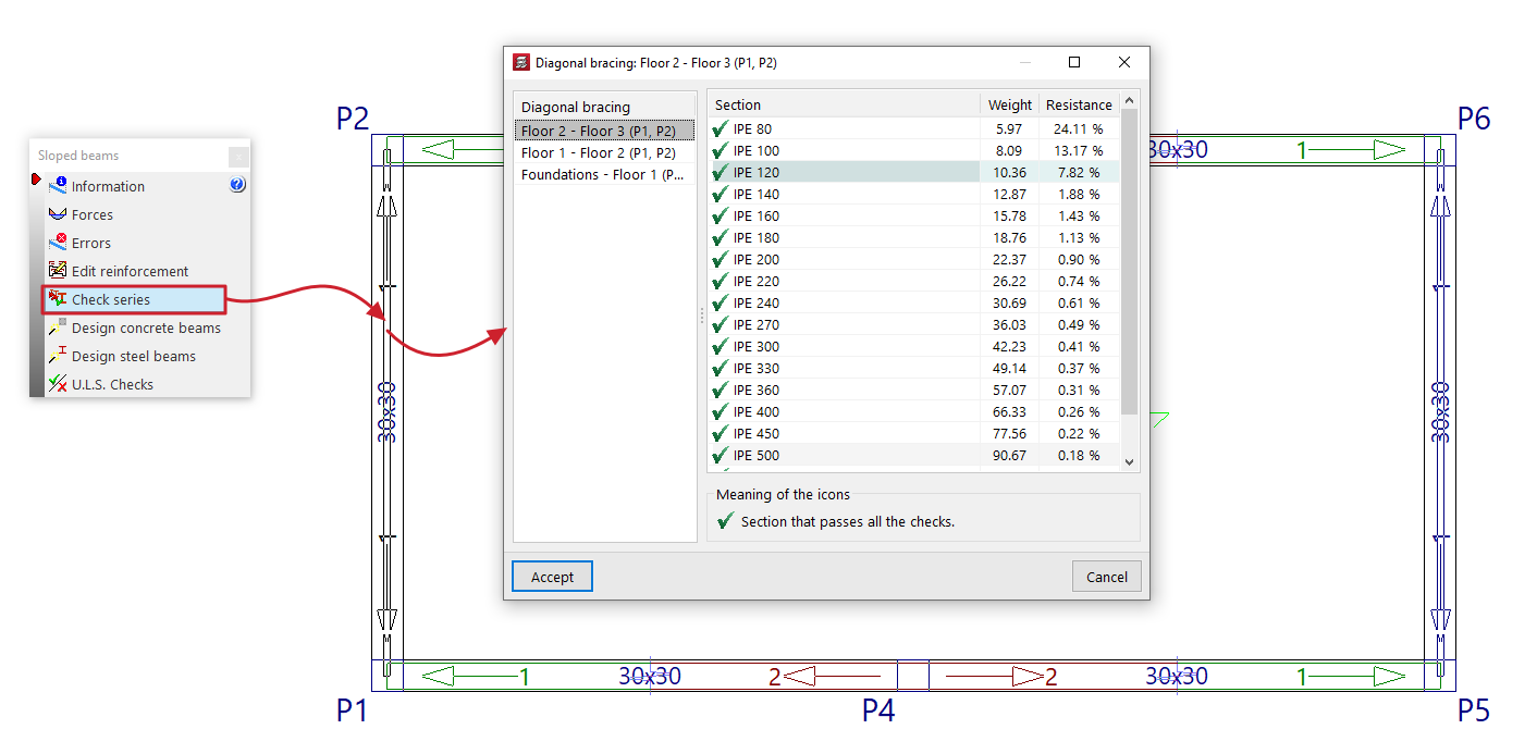
Check series
The "Check series" option allows you to select a sloped steel-section beam, bracing diagonals or V-bracing, and view the selected section—as well as the other sections in the same series—in the pop-up window during the design process.
For each "Section", an icon indicates whether it passes all the checks or not, along with its reference, "Weight" and the demand capacity ratio percentage of "Strength".
If you wish to use a specific section, select that section from the list and click "Accept".
Designing concrete beams
The "Design concrete beams" option redesigns all the sloped reinforced concrete beams in the project using the forces from the most recent analysis.
Designing steel beams
The "Reload steel beams" option re-analyses all sloped steel beams, bracing diagonals and V-bracing in the project using the loads from the most recent analysis.
You can do this "From the first section" in the series or "From the selected section" by selecting the relevant option in the pop-up window.
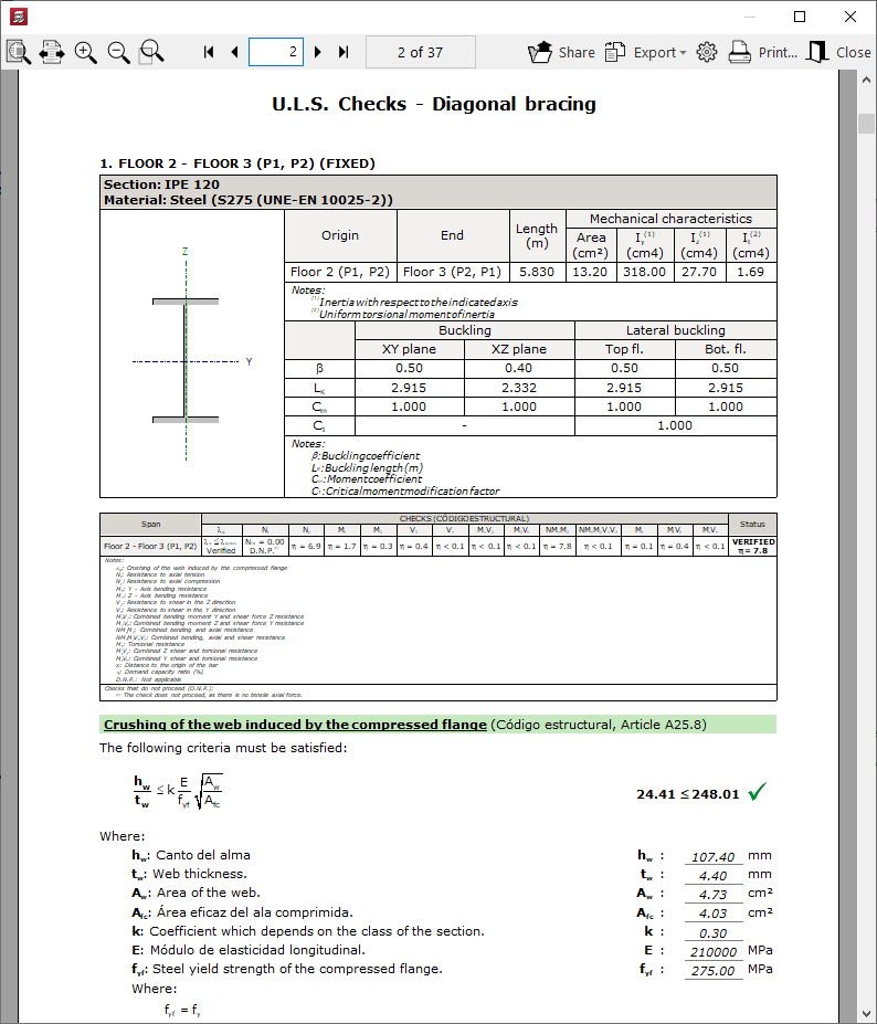
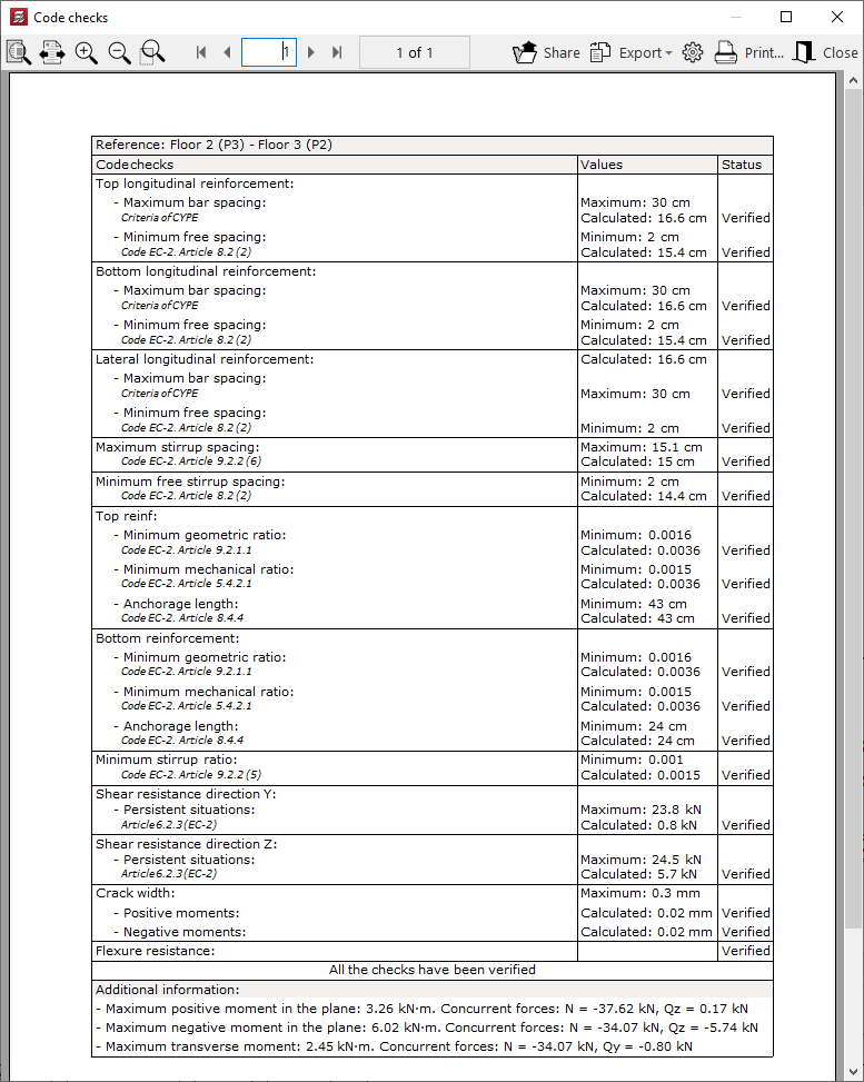
U.L.S. checks
Displays a document detailing the checks carried out on a sloped steel-section beam to verify the Ultimate Limit States corresponding to the selected standard.