Reinforced concrete configuration
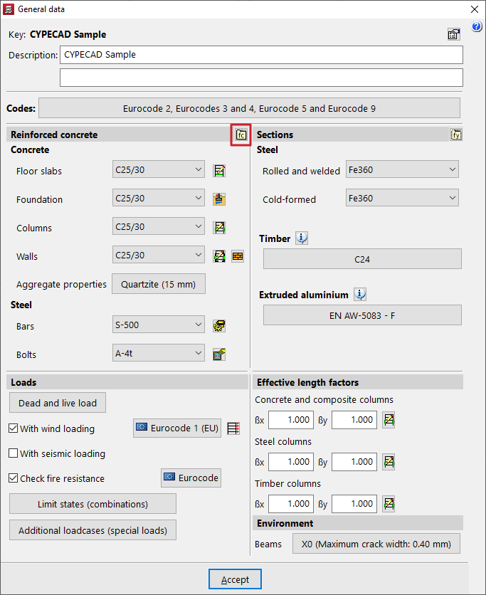
The configuration of reinforced concrete used in elements of this material in CYPECAD is carried out in the "Project" menu by selecting the "General data" option. This menu can be accessed from the different tabs in the program. It also appears automatically when creating a new project.
Options in the "Reinforced concrete" section
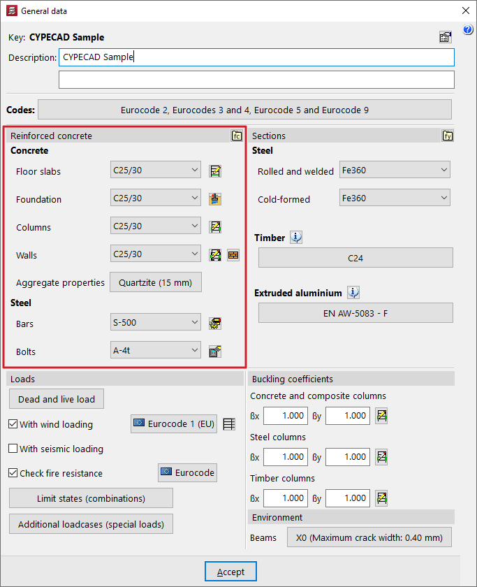
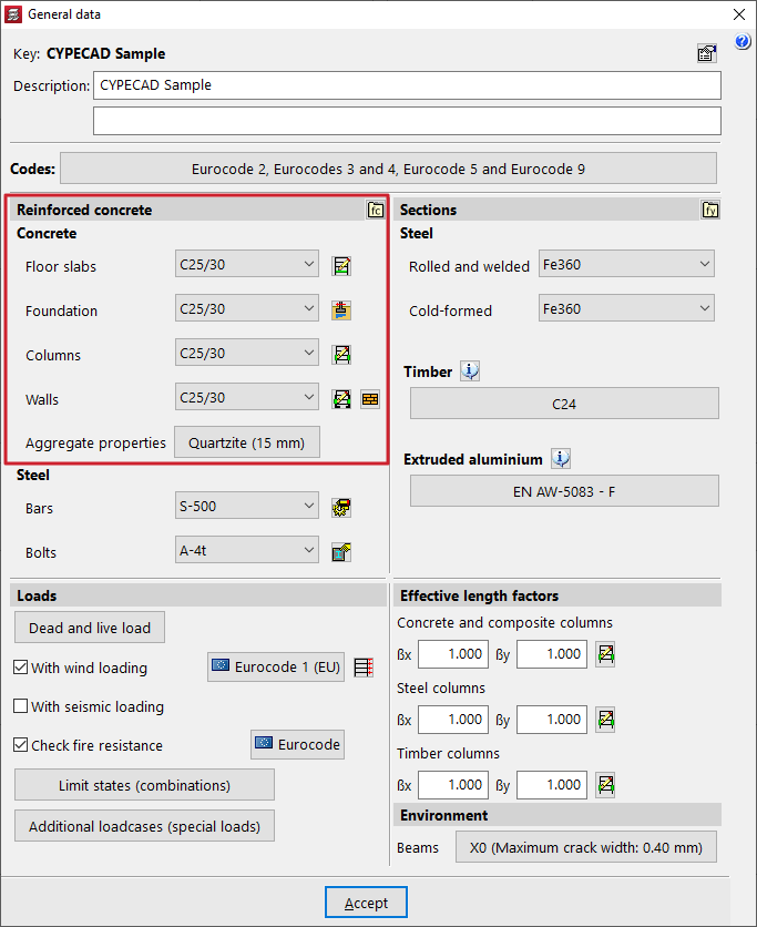
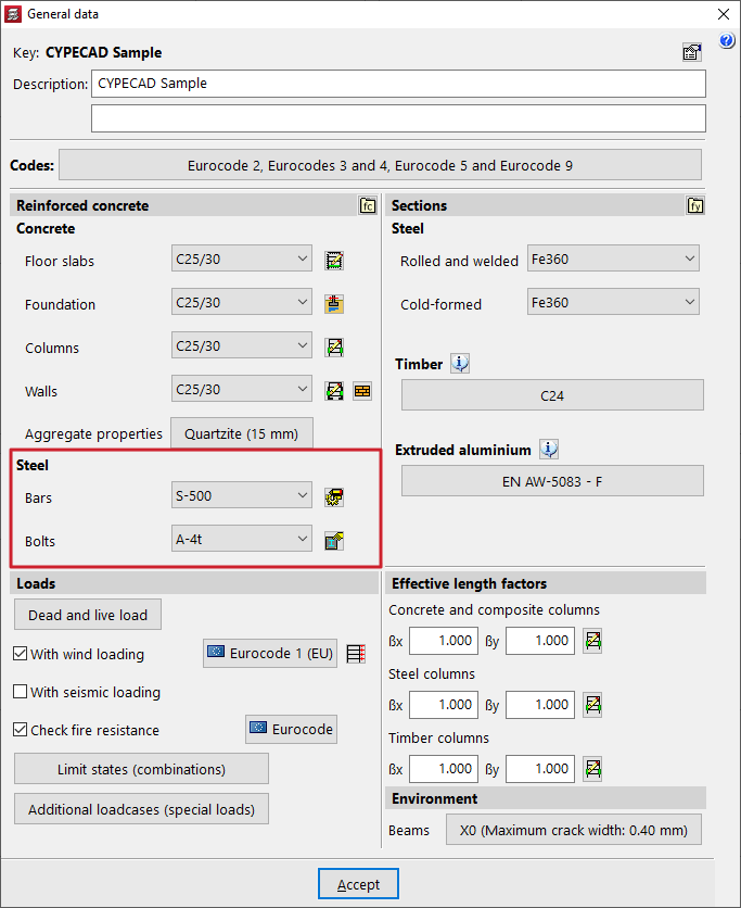
Within the "General data" window, the project materials are defined in the "Reinforced concrete" and "Section" sections.
In the "Reinforced concrete" section, both the "Concrete" and the "Steel" for reinforcement and bolts are configured.
Each of these options is detailed below.
Selecting concrete
The various drop-down menus in this section can be used to select the "Concrete" for the "Floors", "Foundations", "Columns" and "Walls".
The materials that appear as default in the various drop-down menus correspond to those covered by the previously selected standards.
| Note: |
|---|
| The concrete defined in the "Floor slabs" drop-down menu will also be applied to beams, sloping beams, stairs, and concrete elements in integrated 3D structures. |
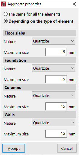
The corresponding section allows you to modify the "Aggregate properties". These can be "The same for all elements" or "Depending on the type of element".
In any case, you can indicate the "Nature" of the aggregate in the drop-down menu, as well as the "Maximum size" of the aggregate.
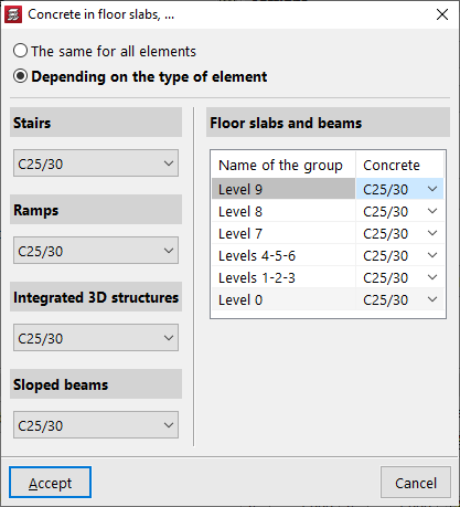
If the project has more than one group, you can click the "By group" button to the right of the "Slabs" drop-down list to select "The same (concrete) for all elements" or "By type".
In the latter case, a different concrete grade can be specified for "Stairs", "Ramps", "Integrated 3D structures" and "Sloping beams".
For slabs and beams, the table on the right-hand side allows a different concrete grade to be defined depending on the group in which they are located.
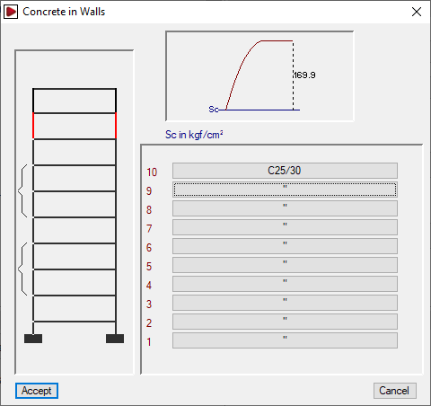
To the right of the "Columns" and "Walls" drop-down lists, the "By floor" button allows the concrete grade assigned to column or wall segments to be defined on a floor-by-floor basis.

User concrete
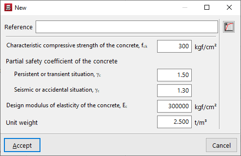
If necessary, you can define a user concrete from the "User concrete library" option and, after clicking on "New", specify its properties.
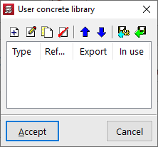
These include the following:
- Reference
- Characteristic compressive strength of concrete
- Partial safety factors for concrete
Defined for persistent or transient situations and for seismic or accidental situations. - Design modulus of elasticity of concrete
- Unit weight
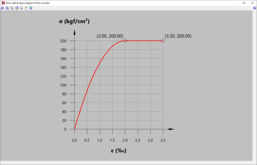
You can also consult the "Concrete stress-strain diagram" using the corresponding option on the right.
User concretes can be exported and imported into other projects. After creating a user concrete, it can be selected from any of the drop-down menus mentioned above.
Selection of reinforcing steel and bolt steel
The reinforcing steel for concrete elements and the steel for bolts is defined in the drop-down menus for the "Bars" and "Bolts" options.
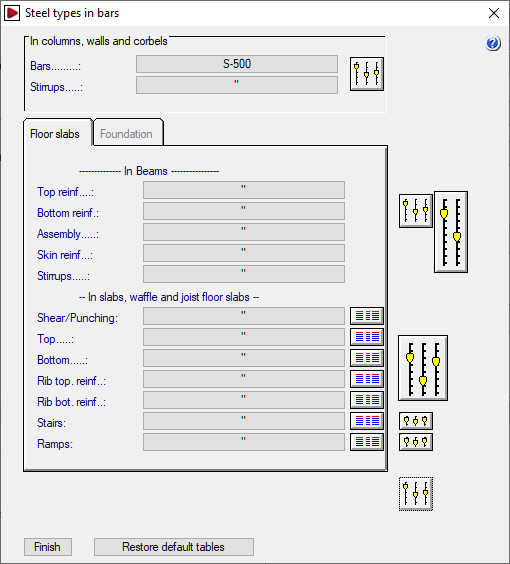
To the right of the "Bars" drop-down menu, the "By position" button allows you to access the "Steel types in bars" window, where you can assign different types of steel depending on their position in the different elements of the structure.
In addition, using the options on the right, you can edit the reinforcement tables and adjust multiple analysis and design options for the reinforcement of each type of element.
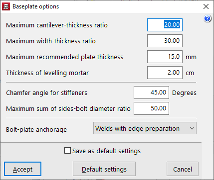
To the right of the "Bolts" drop-down menu, there is a button that allows you to adjust the "Baseplate options", which include the following.
- Relación máxima vuelo-espesor
Este dato se emplea en el dimensionamiento de la placa de anclaje. El espesor será mayor o igual que el valor del cociente vuelo máximo/relación máxima vuelo-espesor. - Relación máxima ancho-espesor
Este dato se emplea en el dimensionamiento de la placa de anclaje. El espesor de la placa será mayor o igual que el valor del cociente ancho máximo/relación máxima ancho-espesor. - Espesor máximo recomendable para placas
Si en el proceso de dimensionamiento es necesario aumentar el espesor por encima del espesor máximo recomendable para placas definido en esta opción, se emplearán rigidizadores. Este valor se puede superar cuando no sea posible emplear rigidizadores, o bien estos no sean suficientes para que la placa cumpla las comprobaciones. - Espesor del mortero de nivelación
- Ángulo en bisel para rigidizadores
- Relación máxima suma de lados-diámetro de pernos
Este parámetro se emplea en el dimensionamiento de los pernos de la placa de anclaje. El diámetro nominal de los mismos debe ser mayor o igual que el valor del cociente (lado X + lado Y) / relación máxima suma de lados-diámetro de pernos. - Anclaje pernos-placa