Soil pressure on walls
A "Soil pressure" pressure law is defined within the "List of pressure laws" for walls by setting one or two backfill situations, "Situation 1" and "Situation 2". The second is optional and can be enabled or disabled.
Filler situations
Filling conditions correspond to different load conditions throughout the structure’s service life:
- For situation 1, the thrust law will be considered to apply under the conditions associated with situation 1.
- For situation 2, the difference between the forces in situation 2 and the forces defined in situation 1 shall be considered, assuming the conditions associated with situation 2. Therefore, the force law for situation 2 must be greater than the force law for situation 1.
Earth pressure
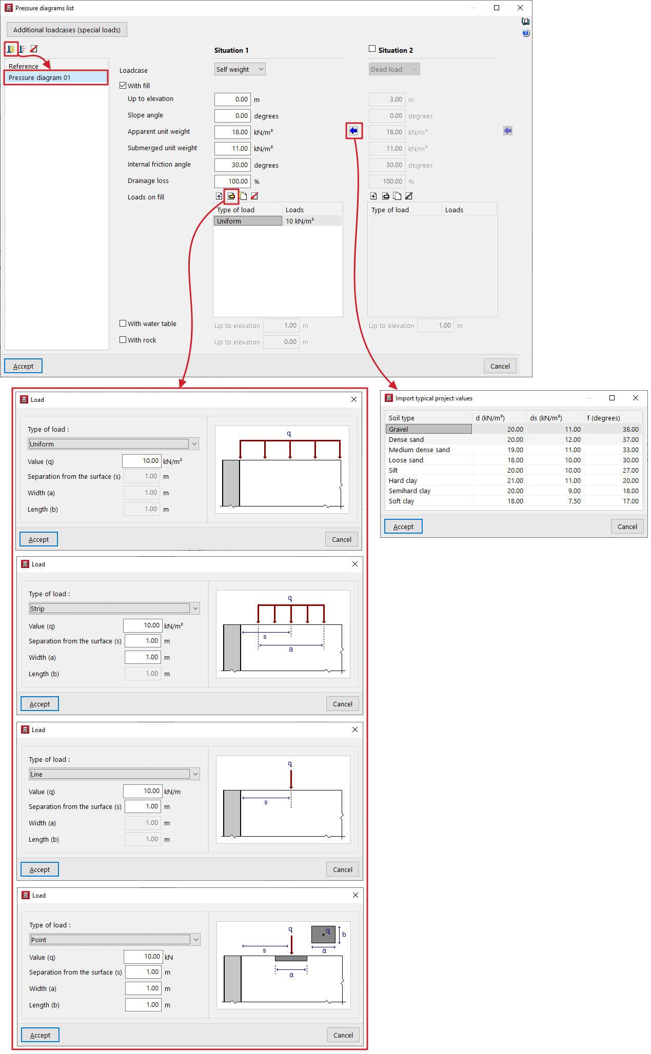
For each fill situation, the following data must be provided in order to define the soil pressure formula:
- First, select the "Loadcase" to which the situation will be linked from those available in the drop-down menu.
- The "With fill" checkbox can then be ticked to indicate the presence of a backfill defined by the following parameters:
- Up to elevation
Elevation in general coordinates of the top of the fill. - Slope angle
If a value is entered for the slope angle, the embankment will have a certain angle of inclination on its surface. This angle is considered to be zero when the surface of the embankment is horizontal, whilst it is positive for a sloping embankment. The minimum value for the slope angle is 0 degrees, whilst the maximum value is limited to that of the soil’s internal friction angle. - Apparent unit weight
Bulk density of the fill material. - Submerged unit weight
Submerged unit weight of the soil. This value enables the assessment of soil pressures below the water table. - Internal friction angle
The internal friction angle of the soil, expressed in degrees. This value can range from 35 to 45 degrees for sandy gravel, compacted sand or rock fill, and from 30 to 35 degrees for loose sand. - Drainage loss
The presence of drainage in the wall can be considered by entering a specific percentage of drainage. The program reduces the total value of the hydrostatic pressure acting on the wall face by the specified percentage. For example, if the percentage of drainage is 100%, even if a water table is defined, the hydrostatic thrust is zero. - Loads on fill
This table allows you to add different types of loads to the fill:- Uniform
Only its "Value (q)" is entered as a surface load. - Strip
Enter its "Value (q)" as a surface load, the "Separation from the surface (s)" from the centre of the strip, and the "Width (a)" of the strip. - Line
Enter the "Value (q)" as a linear load and the "Separation from the surface (s)". - Point load
Enter the "Value (q)" as a point load, the "Separation from the surface (s)" from the centre of the load application, and the "Width (a)" and "Length (b)" of the area where the load is applied.
- Uniform
- Up to elevation
- Further down, the "With water table" box allows you to specify the elevation, in general coordinates, at which the water table is located. Hydrostatic pressure will be taken into account below the water table.
- Finally, the "Rock" checkbox allows you to define the upper level of the rock layer in general coordinates. The program will not apply thrusts below this level.