Inserting pipes and elements of the water distribution network
Within the "Installation" tab, in the "Distribution" group of the main toolbar, pipes and elements in the water distribution network such as valves, pressure and flow regulators and control points can be defined and entered manually.

Pipes
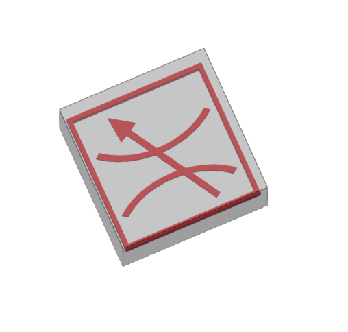
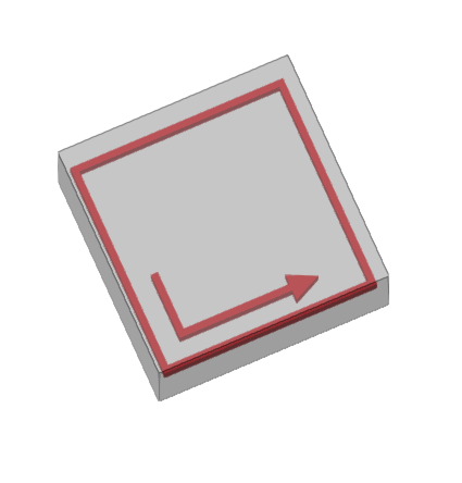
Freely inserts pipes into the model in any direction in space, tracing their layout in the work area.
| Note: |
|---|
| To enter pipe networks as a whole or to generate them automatically from the geometry of the spaces, together with the sprinklers they feed, the corresponding options on the right-hand side of the "Distribution" group can be used. |
When entering a pipe, the following parameters can be configured:
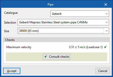
- Catalogue / Series / Diameter
The program selects pipes from "Manufacturer catalogues", if available, or from the "Library of generic elements" using the wizard available on the right. These types of elements can be created and edited from the "Catalogue management" and "Library of generic elements" options, respectively, within the "Project" group.
The checks to be carried out on the pipes can be defined in "Pipe options", accessible from "General options", in the "Project" group of the top toolbar. After the analysis, the program can consult the verification of the checks defined in the editing panel of each pipe span.
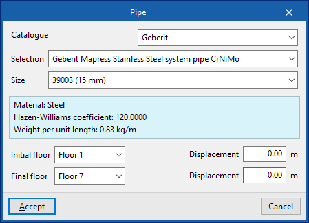
Riser
Enters a vertical pipe or riser by specifying a "Initial floor" and an "Final floor". On each of these floors it is possible to specify a "Displacement" to adjust the position of the end points of the riser.
The remaining parameters are identical to those that appear when using the "Pipe" option.
The "Valves" menu allows you to enter elements of the "Valve", "Control station", "Pressure regulator", and "Flow regulator" types:
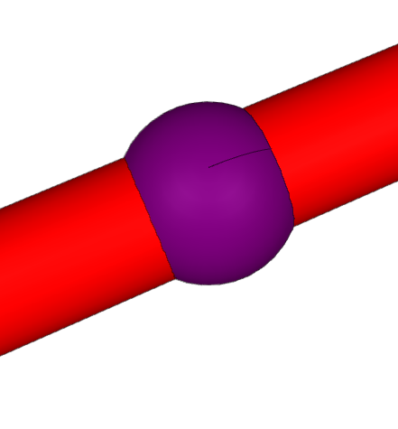
Valves
Inserts a valve into the distribution network. This way, the program considers the associated pressure losses.
When entering or editing a valve, the following parameters can be configured:
- Reference
Valve reference. - Selection
The program selects a valve from the "Library of generic elements" using the wizard available on the right. These types of elements can be created and edited from the "Library of generic elements" option in the "Project" group.

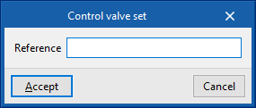
Control valve set
Inserts a control valve set.
The control valve set is an assembly comprising the alarm valve, the shut-off valve, and all valves and fittings needed to control a hydraulic extinguishing installation.
The maximum size of the installation controlled by a control valve set depends on the risk of the building and is set out in the related codes.
The "Maximum protected surface by control valve set" can be defined for each type of space by activating the corresponding option under "General options" in the "Project" group of the upper toolbar.
If the maximum allowable limit is exceeded, the program will report this after the analysis so that the necessary measures can be taken.
| Note: |
|---|
| For the UNE EN 12845 standard, the maximum size of the installation controlled by a control valve set varies between 9000 and 12000 m², depending on the type of risk of the space. |
When entering or editing a checkpoint, the following parameters can be configured:
- Reference
Control valve set reference.
Additionally, the design process can be carried out only for the part of the system downstream of a given control point.
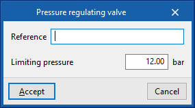
Pressure regulating valve
Inserts a pressure regulating valve.
This element limits the pressure in the hydraulic fire extinguishing system downstream of its installation point.
When entering or editing a pressure regulating valve, the following parameters can be configured:
- Reference
Pressure regulating valve reference. - Limiting pressure
Value of the pressure limited by the regulating valve.
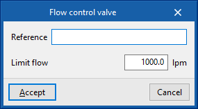
Flow control valve
Inserts a flow control valve.
This element limits the flow in the hydraulic fire extinguishing system downstream of its installation point.
When entering or editing a flow control valve, the following parameters can be configured:
- Reference
Flow control valve. - Limit flow
Flow rate value limited by the control valve.