Inserting VRF systems
Under the "Installation" tab, in the "VRF" menu within the "Direct expansion" section of the main toolbar, you will find the options for defining and entering the components of the variable refrigerant flow (VRF) systems supported by the program:

- VRF
- Outdoor unit, heat pump (2-pipe system)
- Outdoor unit with heat recovery (3-pipe system)
- Flowchart
- Manifold
- Referral
- Indoor unit, cassette
- Indoor unit, wall-mounted
- Indoor unit, floor-standing
- Indoor unit, ceiling
- Indoor unit, water production
- Indoor unit, with distribution using ducts
- Centralised control
- Automatic routing (VRF)
The available equipment and options are as follows:
Outdoor units
The options for installing the outdoor units of VRF systems and their associated components are as follows:
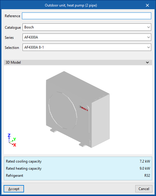
- Outdoor unit, heat pump (2-pipe system)
This unit supplies cooling to all indoor units simultaneously or heating to all indoor units simultaneously. - Outdoor unit, with heat recovery (3 pipe)
This unit is capable of providing cooling to some indoor units and heating to other indoor units simultaneously. To do this, a flow box must be installed upstream of each indoor unit. - Flow box
This device is used in systems with an outdoor unit featuring heat recovery (3-pipe system). Typically, one flow box is provided for each indoor unit, although it is also possible to supply several indoor units from a single flow box.
When adding an outdoor unit to a VRF system, the following parameters must be specified:
- Reference
- Catalogue / Series / Selection
Allows you to select and import data from manufacturer catalogues previously loaded using the "Catalogue management" option. - 3D model:
Three-dimensional view of the selected equipment. - Nominal heating capacity / Nominal cooling capacity / Refrigerant
Nominal capacities and type of refrigerant for the selected unit.


Indoor units
The options for installing indoor units for VRF systems are as follows:
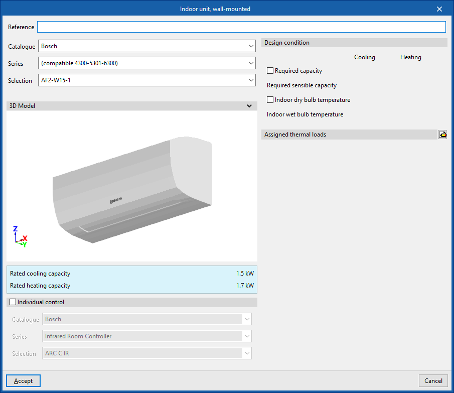
- Indoor unit, cassette
- Indoor unit, wall-mounted
- Indoor unit, floor-standing
- Indoor unit, ceiling
- Indoor unit, water production
- Indoor unit, with distribution using ducts
This unit has two openings for air intake and exhaust, which can be connected by inserting air ducts from the options in the "Air Distribution" section.
When installing an indoor unit for a VRF system, the following parameters must be specified:
- Reference
- Catalogue / Series / Selection
Allows you to select and import data from manufacturer catalogues previously loaded using the "Catalogue management" option. - 3D model:
Three-dimensional view of the selected equipment. - Nominal heating capacity / Nominal cooling capacity / Airflow (for "Indoor unit, ducted")
Specifications of the selected unit. - Individual control (optional)
Selecting this option enables individual control of the equipment.- Catalogue / Series / Selection
Allows you to select and import data from manufacturer catalogues previously loaded using the "Catalogue Management" option.
- Catalogue / Series / Selection
- Design specifications
- Power requirement (Cooling / Heating) (optional)
- Required apparent power (Cooling) (optional)
- Dry-bulb indoor temperature (Cooling / Heating) (optional)
- Internal wet-bulb temperature (Cooling) (optional)
- Check the maximum refrigerant charge (optional)
The "Space", "Area",
"Height" and "Volume" are displayed, indicating whether it is a "Basement".
The "R32 leak detector" checkbox allows you to specify whether the indoor unit is fitted with this component. This box will be ticked automatically if the "Add countermeasures automatically" option is enabled in the "General options". Furthermore, when an indoor unit already has a factory-fitted R32 detector, it will be ticked to make it easier for the user to understand.
- Assigned thermal loads
This allows you to define the following percentages of the heating and/or cooling thermal load values for the project. The program automatically assigns loads based on the layout of the terminal elements in the model.- % Rated heating power
- % Total rated cooling capacity
- % Rated cooling capacity
- % Heating load required
- % Total cooling load required
- % Required sensible cooling load


Manifolds and branches
These options allow you to configure the following components of a VRF system installation:
- Manifold
This allows a manifold to be installed between the outdoor unit and the indoor units. At certain points in the installation, the main pipe must supply several indoor units located at similar distances. In such cases, rather than using branch pipes that are very close to one another, it is advisable to install a manifold with 4 or 8 outlets. - Branch
Enters branches manually. The program automatically places a branch at all junctions where necessary. This option allows you to enter branches manually at the desired points.


| Note: |
|---|
| These units are connected to one another using the "Refrigerant line" option in the "Direct expansion" block. It is also possible to use the "Vertical pipe" option, specifying the elevation of the end point by selecting a floor and entering an offset, and marking a point in the workspace as the starting point. |
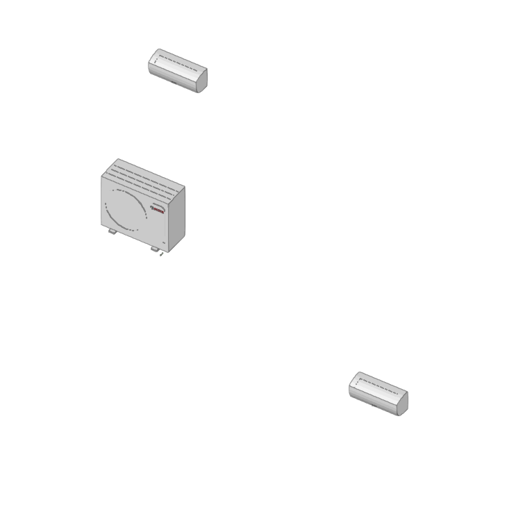
Centralised control
These options allow you to configure the centralised control of a VRF system:
- Reference
- Catalogue / Series / Selection
Allows you to select and import data from manufacturer catalogues previously loaded using the "Catalogue Management" option. - Units (Reference / Selection)
Allows you to select the outdoor units associated with the centralised control system.


Automatic routing (VRF)
This option allows you to select the units in the variable refrigerant flow (VRF) systems within the model and automatically generate the refrigerant piping layout between them. If necessary, you can subsequently adjust the generated piping layout using the element editing tools.