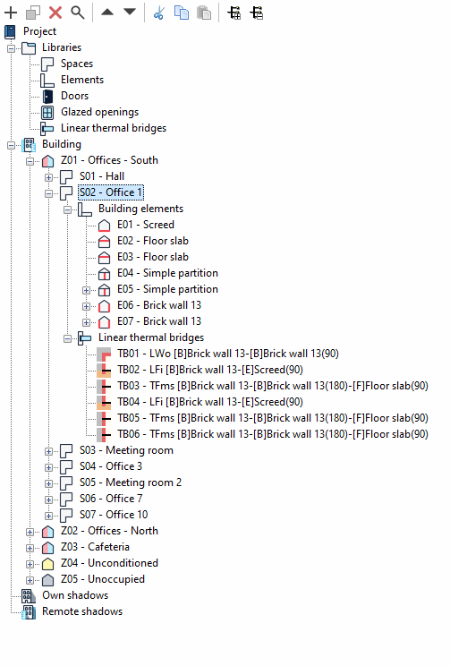
Project tree diagram ("Building" tab)
In the "Building" tab, under the "Project" section, the program displays the model’s tree structure.
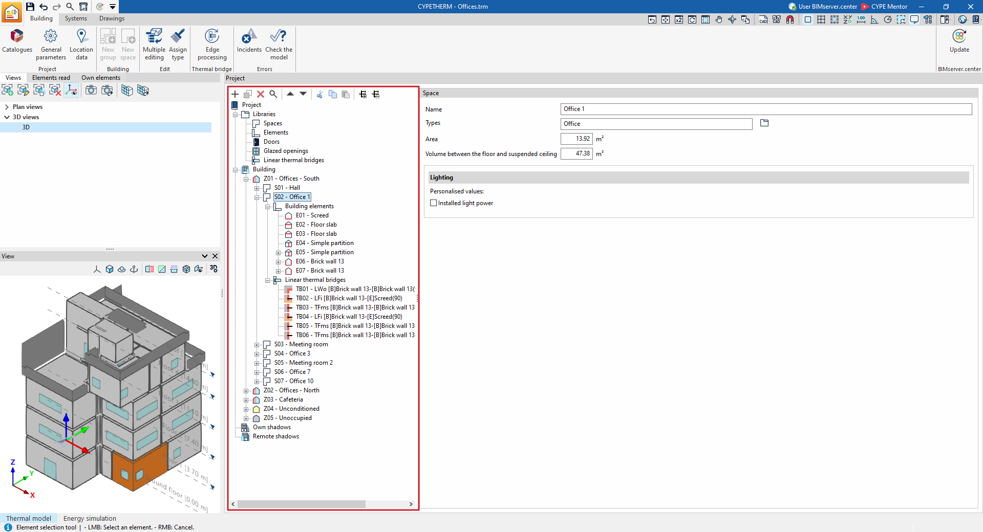
This tree view consists of the following branches, which can be expanded or collapsed:
- Libraries
In the library, you can enter the types of building areas and structural elements (façades, party walls, partition walls, curtain walls, basement walls, roofs, overhangs, intermediate floor slabs and screeds), doors, glazed openings (such as windows and skylights) and linear thermal bridges within the building.- Spaces
- Elements
- Doors
- Glazed openings
- Linear thermal bridges
- Building
This section allows you to define the building’s thermal model, structured into zones and compartments. The compartments that make up each zone are entered here. For each compartment, the structural elements and linear thermal bridges that form part of it are defined:- Zone
- Space
- Building elements
- Linear thermal bridges
- Space
- Zone
- Own shadows (in the "Energy simulation" project type)
This refers to building surfaces that do not form part of the enclosures but which may cast shadows on façades and roofs, such as balcony slabs or parapets. - Remote shadows (in the "Energy simulation" project type)
The surfaces of remote obstacles that may cast shadows on the building are defined.