

Defining fans and circulation pumps
Within centralised air-conditioning systems, the relevant characteristics of the working fluid distribution network are also defined, including the equipment used to transport the fluid, namely fans and circulation pumps.
Terminal units that blow air, such as fan coils, direct expansion (refrigerant) indoor units and heat recovery units, also contain fans.
The electricity consumption of this auxiliary equipment is included in the consumption figures for heating and cooling services, with the exception of the consumption of fans in centralised ventilation systems, which is allocated to the ventilation service.
Fans
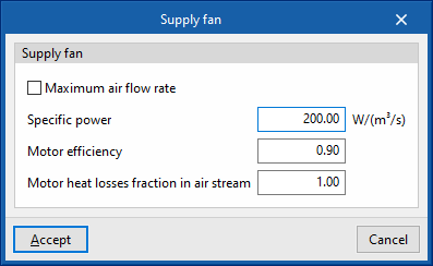
Fans are defined in a similar way across all the devices in the program:
- Maximum air flow / Air flow (optional)
The air flow passing through the fan. If the panel displays "Maximum air flow", the air flow may vary during the simulation up to the value set in this box. If the air flow rate is not specified, the program will calculate the required flow rate. - Specific power
The electrical power required by the fan per m³/s of air flow it moves. If the efficiency value of the air-conditioning unit includes the fan’s power consumption, the specific power value can be set to 0 to avoid double-counting this consumption. - Motor performance
This is taken into account when calculating the heat losses of the electric fan motor, which will affect the supply air temperature as defined in the following variable. - Proportion of motor heat losses in the air flow
If the supply air passes through the fan motor, the motor’s heat losses will cause the air temperature to rise. To take this into account, a value of 1 must be set. If, on the other hand, the fan motor is located outside the air flow, its heat losses will not affect the air, so a value of 0 must be entered. Any intermediate value may be assigned if desired.
Circulating pumps
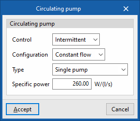
Circulating pumps are also defined in a similar way in the various types of hydraulic circuits:
- Control
- Intermittent
If the control is set to intermittent, the pump switches on and off in tandem with the air-conditioning system. - Continuous
If the control is continuous, the pump is always running, even when there is no demand. During long periods without demand, heat losses from the pump accumulate in the fluid, which can cause a noticeable rise in its temperature.
- Intermittent
- Configuration
The "Constant flow" and "Variable flow" options represent a fixed-speed and variable-speed pump, respectively. - Type
Select the number of identical pumps in the hydraulic circuit and their position. - Specific power
The electrical power required by the pump per litre per second of water flow it moves.
The water flow rate in the circuit is automatically determined by the calculation engine based on the heating or cooling demand for the design day and the "Design temperature difference" specified for the hydraulic circuit.