
Direct expansion systems
Direct expansion systems include variable refrigerant flow (VRF) systems and multi-split systems, which are connected to the corresponding direct expansion terminal units.
Other direct expansion systems, such as 1x1 split systems or compact units, are modelled as stand-alone terminal units and do not require the inclusion of an air-conditioning system in the relevant section.
Variable refrigerant flow (VRF)
Catalogues
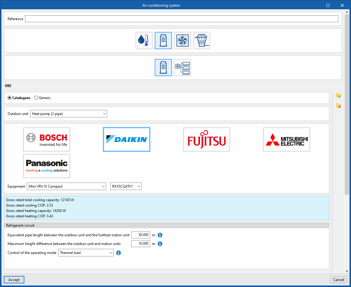
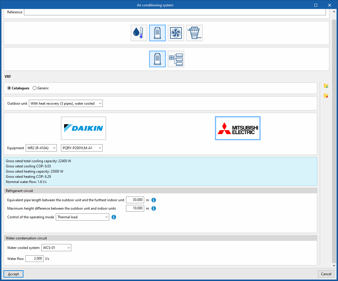
The "Catalogues" option lets you simulate a manufacturer’s VRF system.
To do this, select the "Outdoor unit" for the variable refrigerant flow system from the following options:
- Heat pump (2-pipe)
- Heat pump (2-pipe system), water-cooled
- With heat recovery (3 pipes)
- With heat recovery (3 tubes), water-cooled condensation
Next, the "Equipment" must be selected from the manufacturers and models available in the Open BIM Database, which have been downloaded beforehand via the "Catalogues" option on the main interface.
The program displays the specifications of the selected device in the information box.
In addition, the following parameters are configured:
Refrigerant circuit
- Equivalent pipe length between the outdoor unit and the furthest indoor unit
The length of the refrigerant pipes is used to adjust the capacity of the VRF system, in accordance with the manufacturer’s instructions. - Maximum height difference between the outdoor unit and indoor units
The height difference between units is used to adjust the capacity of the VRF system, in accordance with the manufacturer’s instructions. The height difference is indicated with a positive sign if the outdoor unit is installed above the indoor units, and with a negative sign if the outdoor unit is installed below the indoor units. - Control of the operating mode
During the simulation, the system automatically switches between cooling and heating modes depending on the selected control mode:- Thermal charge
The operating mode corresponds to the highest value of thermal power required. - Number of zones
The operating mode corresponds to that required by the majority of the zones served by the system. - Zone with greatest deviation
The operating mode required by the zone whose temperature deviates most from its setpoint is adopted. - Control zone
The operating mode specified by the selected control zone is adopted. The control zone must contain an indoor unit connected to this outdoor unit.- Zone name for master thermostat location
- Thermal charge
Water-cooled condensing circuit (in "Heat pump (2-pipe), water-cooled" and "With heat recovery (3-pipe), water-cooled")
- Water-cooled system
Select a water-cooled condensing system as defined in the "Air-conditioning systems" section. - Water flow
Generic
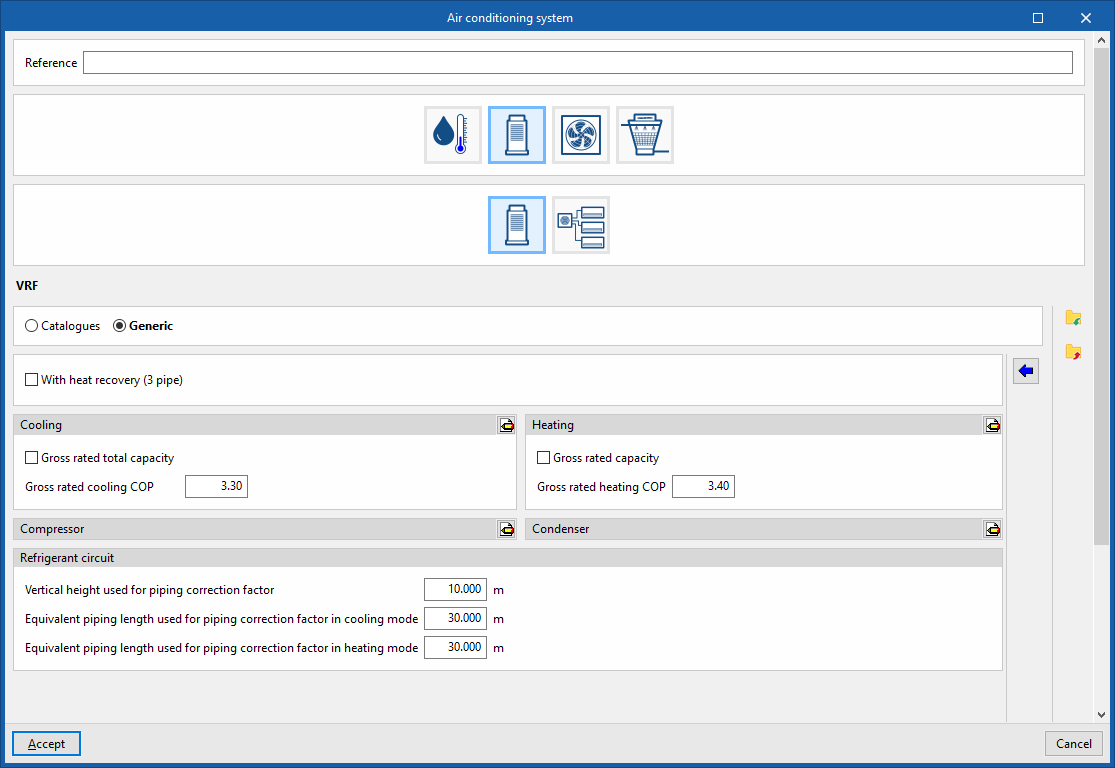
Simulate a generic variable refrigerant flow system and configure the following parameters:
Features
- With heat recovery (3 pipes) (optional)
If this option is enabled, the following "Operating limit temperatures" can be adjusted in "Heat recovery mode":- Minimum outdoor temperature in heat recovery mode
- Maximum outdoor temperature in heat recovery mode
Cooling
- Rated total power (optional)
Specify a value for the unit’s rated total power in cooling mode. - Nominal cooling COP
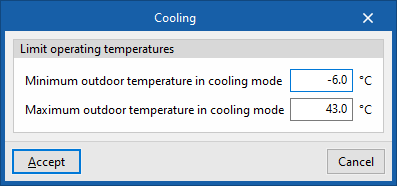
- Advanced settings:
- Limit operating temperatures
- Minimum outdoor temperature in cooling mode
- Maximum outdoor temperature in cooling mode
- Limit operating temperatures
Heating
- Rated power (optional)
Specify a value for the unit’s total rated heating power. - Gross rated heating COP
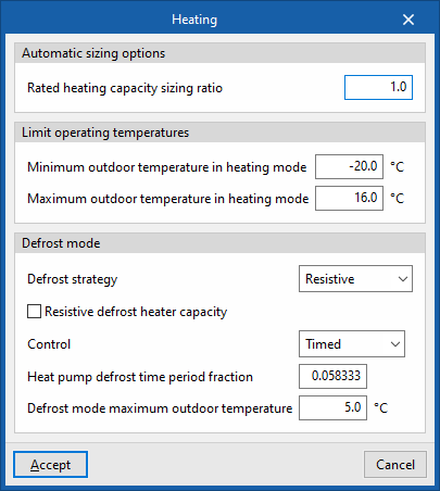
- Advanced settings:
- Automatic sizing options:
- Rated heating capacity sizing ratio
- Limit operating temperatures
- Minimum outdoor temperature in heating mode
- Maximum outdoor temperature in heating mode
- Defrost mode
- Defrost strategy (Cycle reversal / Resistive)
- Power of the resistive defrost heater (in "Resistive" mode)
- Control (Timed / On-demand)
- Heat pump defrost time period fraction (in "Programmed" mode)
- Defrost mode maximum outdoor temperature
- Defrost strategy (Cycle reversal / Resistive)
- Automatic sizing options:
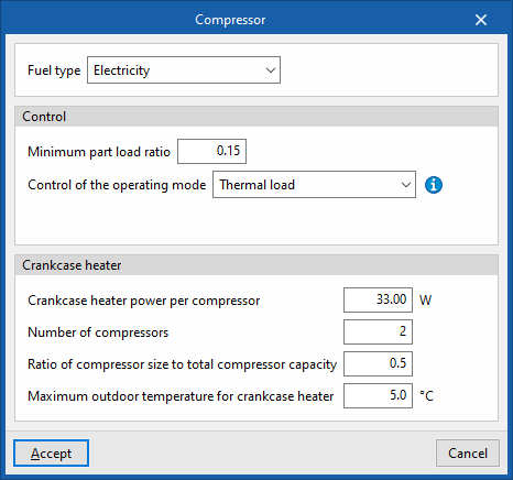
Compressor
- Fuel type (Electricity / Natural gas / LPG / Heavy fuel oil / Biomass / Densified biomass (pellets))
- Control
- Minimum part load ratio
- Control of the operating mode
During the simulation, the system automatically switches between cooling and heating modes depending on the selected control mode:- Thermal load
The operating mode corresponds to the highest value of thermal power required. - Number of zones
The operating mode corresponds to that required by the majority of the zones served by the system. - Zone with greatest deviation
The operating mode required by the zone whose temperature deviates most from its setpoint is adopted. - Control zone
The operating mode specified by the selected control zone is adopted. The control zone must contain an indoor unit connected to this outdoor unit.- Zone name for master thermostat location
- Thermal load
- Crankcase heater
- Crankshaft heater power per compressor
- Number of compressors
- Ratio of compressor size to total compressor capacity
- Maximum outdoor temperature for crankcase heater
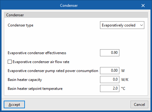
Condenser
- Condenser type (Air-cooled / Water-cooled / Evaporatively cooled)
- Air-cooled
- Water-cooled
- Water-cooled system
- Water condenser volume flow rate (optional)
- Evaporatively cooled
- Evaporative condenser effectiveness
- Evaporative condenser air flow rate (optional)
- Basin heater capacity
- Basin heater setpoint temperature
Refrigerant circuit
- Vertical height used for piping correction factor
- Equivalent piping length used for piping correction factor in cooling mode
- Equivalent piping length used for piping correction factor in heating mode
Multisplit
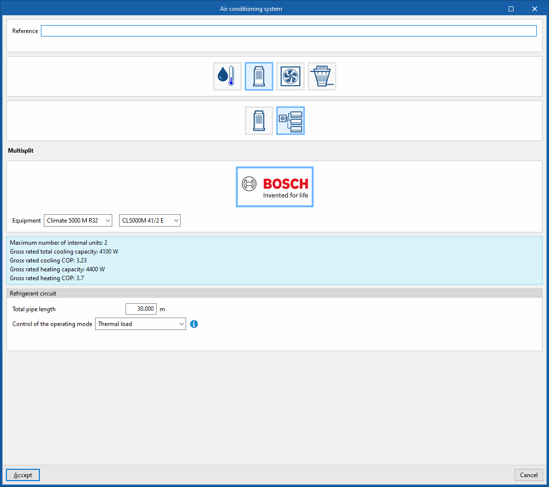
In the "Equipment" section, the program lets you select the outdoor unit for a multi-split system from the manufacturers and models available in the Open BIM Database, which have been downloaded beforehand via the "Catalogues" option in the main interface.
The program displays the specifications of the selected device in the information box.
In addition, the following parameters are configured:
Refrigerant circuit
- Total pipe length
- Control of the operating mode
During the simulation, the system automatically switches between cooling and heating modes depending on the selected control mode:- Thermal load
The operating mode corresponds to the highest value of thermal power required. - Number of zones
The operating mode corresponds to that required by the majority of the zones served by the system. - Zone with greatest deviation
The operating mode required by the zone whose temperature deviates most from its setpoint is adopted. - Control zone
The operating mode specified by the selected control zone is adopted. The control zone must contain an indoor unit connected to this outdoor unit.- Zone name for master thermostat location
- Thermal load