
Entering and editing DHW systems
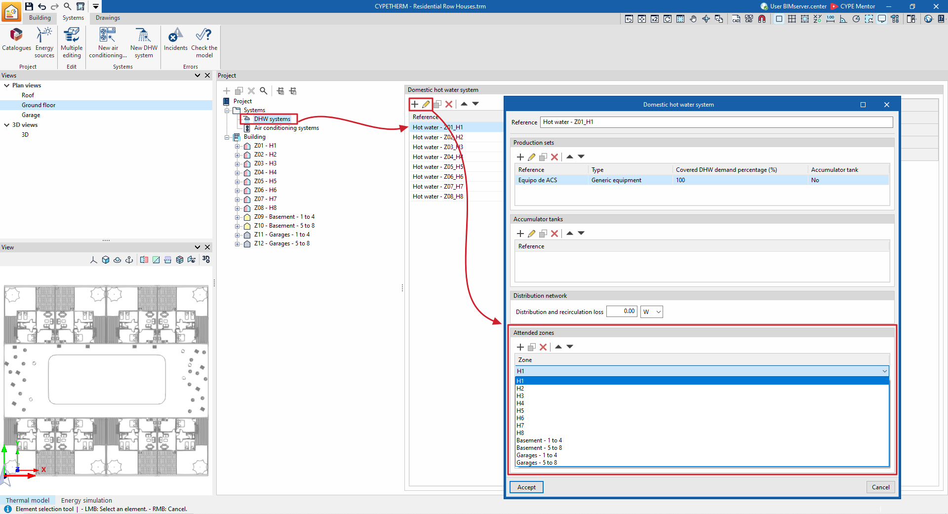
The systems responsible for producing domestic hot water (DHW) for the building are defined in the "DHW systems" section of the tree structure in the left-hand side panel of the "Building" tab.
A DHW system consists of a set of DHW production units and, optionally, a set of accumulator tanks.
Defining DHW systems
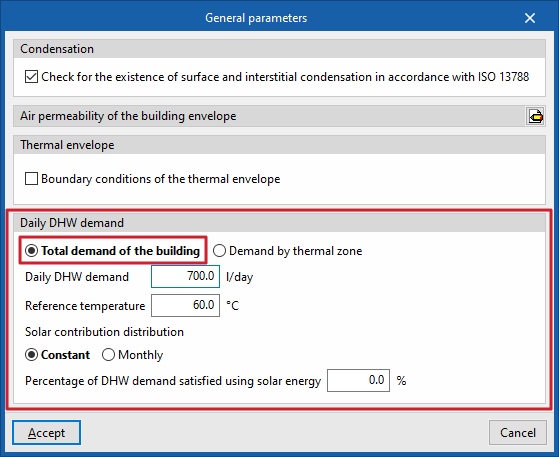
The definition of DHW systems depends on the option selected in the "Daily DHW demand" section, under "General parameters", in the top toolbar of the "Building" tab.
Designing a single DHW system for the entire building
If "Total demand of the building" has been selected under "General parameters", you can define a single DHW system to meet this demand.
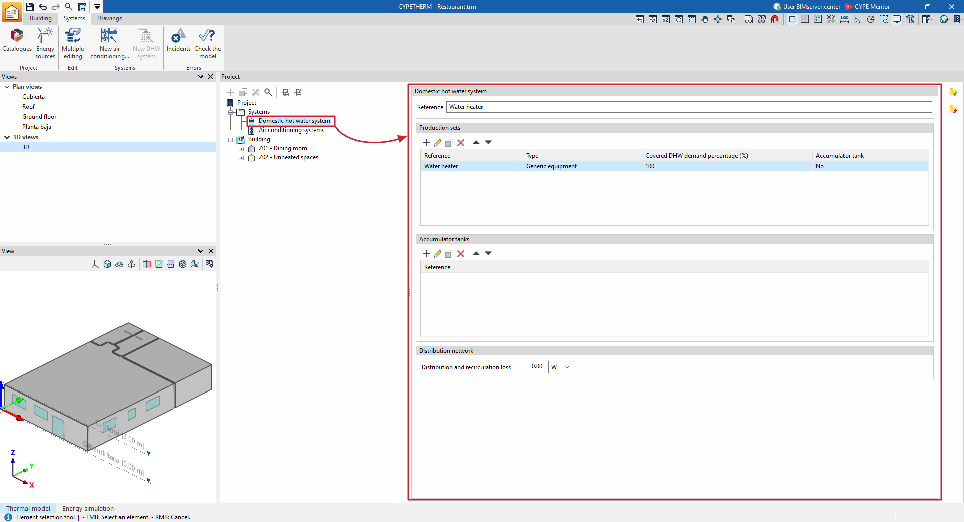
Next, to manually define the DHW system, select "Domestic hot water systems" from the "Systems" drop-down menu in the building diagram, and add the production units and accumulator tanks in the "Domestic hot water systems" panel that appears in the main area.
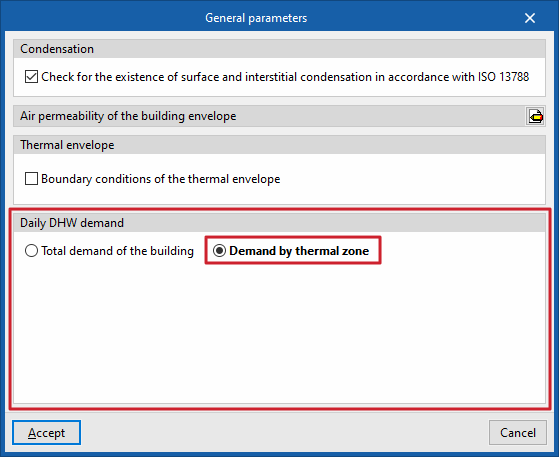
Defining multiple DHW systems serving one or more heating zones
If you select "Demand by heating zone" in the "General parameters", you can define more than one system and select the zones served by each one.
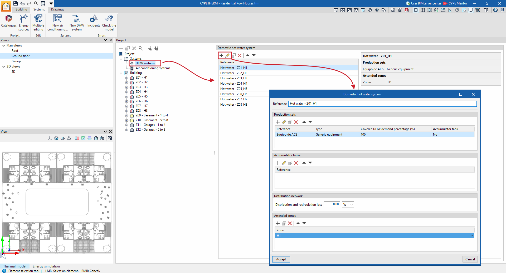
Next, to manually add a new DHW system, select "Domestic hot water systems" from the "Systems" drop-down menu on the building diagram, and click the "Add" button on the top toolbar. This opens the editing window.
When you create different DHW systems, the program will add them to the list of DHW systems in this section.
Similarly, you can select and "Edit" each of the DHW systems created in the list to modify their properties in their edit window.
Defining systems using the wizard
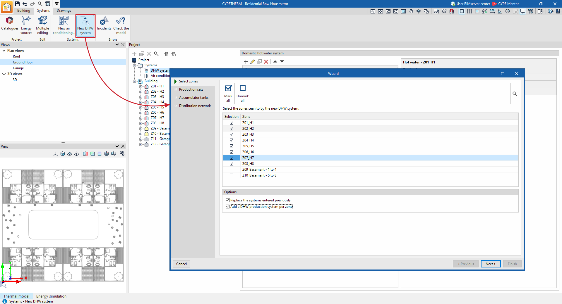
If the "Demand by heating zone" option has been enabled in "General parameters", DHW systems can also be defined using the wizard that appears when you select the "New DHW system" option, available in the "Systems" section of the top toolbar.
In this wizard, you first select the areas served by the new DHW system being entered, using the options "Replace previously entered systems" and/or "Add a DHW production system per area".
The following steps then define the "Production units", the "Storage units" and the losses in the "Distribution network" associated with the system.
When you accept, the program will create the necessary DHW systems, assigning them to all or individual zones, depending on the configuration defined
DHW production units
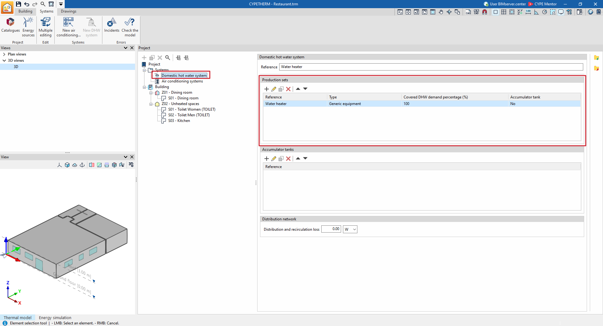
The "Production sets" section provides a list containing the definitions of the equipment that meets the DHW demand allocated to the DHW system currently being edited.
ACS production sets require the following parameter to be defined:
- Covered DHW demand percentage
The proportion of this demand met by each unit must be specified. The set of production units defined in the system must cover the entire DHW demand; that is, the sum of the percentages must be 100 per cent.
Next, you must select the type of DHW production equipment from the following:
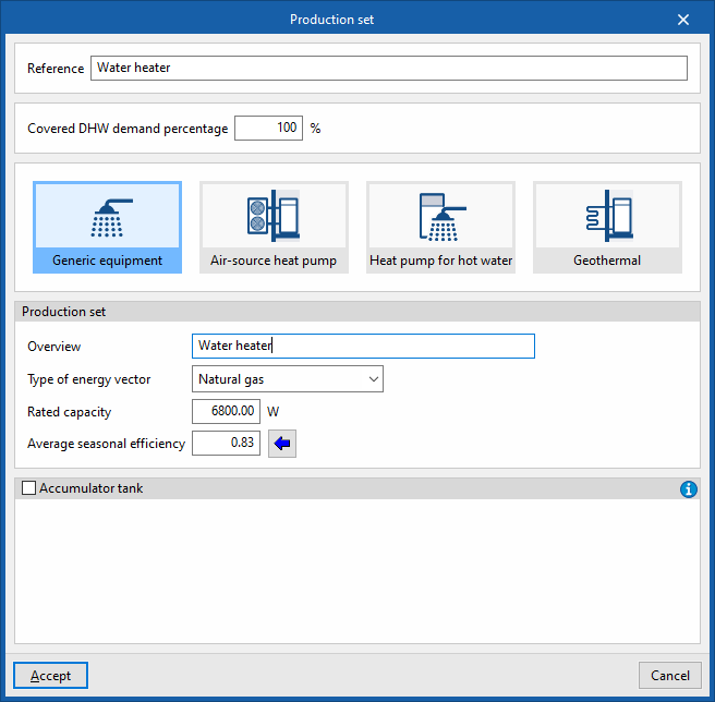
Generic equipment
Simulate any DHW production system based on the energy source it uses and its average seasonal efficiency.
- Production team
- Description
- Type of energy source (Electricity / Natural gas / Heavy fuel oil / LPG / Coal / Biomass / Densified biomass (pellets))
- Rated power
This figure is not taken into account in the energy simulation and is used solely for the purpose of compiling the result reports. - Average seasonal efficiency
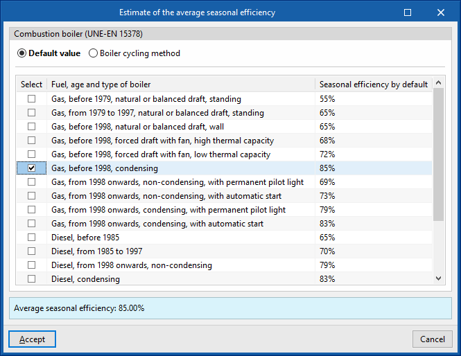
A wizard is provided to carry out the "Estimation of average seasonal efficiency" for combustion boilers, in accordance with the UNE-EN 15378 standard. This can be done:- Default value
Import the "Default seasonal efficiency" based on the selected "Fuel, age and type of boiler" (Table B.3 of UNE-EN 15378). - Boiler cycling method
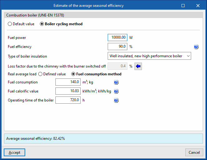
The boiler cycling method (Annex N of UNE-EN 15378) can be used, which calculates seasonal efficiency using a more accurate estimate if technical and consumption data for the equipment are available:- Fuel power
- Fuel efficiency
In existing installations, this figure is obtained from a combustion analysis carried out during the boiler’s periodic inspection. If this figure is not available, the boiler’s efficiency value may be used, which will yield conservative results. - Type of boiler insulation (Well insulated, new high performance boiler / Well insulated and maintained / Old boiler with average insulation / Old boiler with bad insulation / Not insulated)
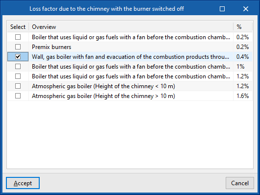
- Loss factor due to the chimney with the burner switched off
This value can be imported using the wizard on the right, depending on the type of boiler and its installation. - Real average load
This value can be set directly or derived from the fuel consumption method.- Defined value
- Fuel consumption method
- Fuel consumption Actual fuel consumption must be expressed in the same units (volumetric or mass) as those used to express its calorific value.
- Fuel calorific value
The lower or higher calorific value of the fuel is stated, depending on the value used to express the combustion output. It must be expressed in the same units (volumetric or mass) as those used to express fuel consumption. - Operating time of the boiler
The operating time is the number of hours during which the boiler has been available for use, over the period to which the fuel consumption refers.
- Default value
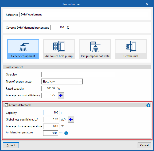
Optionally, the characteristics of a accumulator tank that is either integrated into or associated with the production unit can be defined. Any losses associated with storage will be allocated to this unit (rather than to the system’s equipment as a whole) and covered by it. This option lets you define units such as electric water heaters.
The data required for the accumulators associated with the production equipment are as follows:
- Battery (optional)
- Capacity
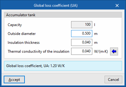
Volume of the accumulator tank. - Overall heat loss coefficient, UA
A wizard is provided to calculate the UA value of the accumulator tank based on the characteristics of its insulation, in accordance with the IDAE document "Technical Guide: Design and analysis of thermal insulation for pipework, appliances and equipment’.- Capacity
Volume of the accumulator tank, based on the figure entered on the previous screen. - Outer diameter
Outer diameter of the accumulator. - Insulation thickness
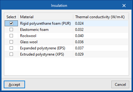
Insulation thickness in the accumulator tank casing. - Thermal conductivity of the insulation
This value can be imported from the material selected in the wizard on the right.
- Capacity
- Average storage temperature
The average temperature of the water stored in the unit. - Ambient temperature
The average ambient temperature of the room where the DHW accumulator tank is installed.
- Capacity
| Note: |
|---|
| If you have defined an accumulator associated with a production unit in this section, you must not define it again in the list of accumulators in the ACS system. |
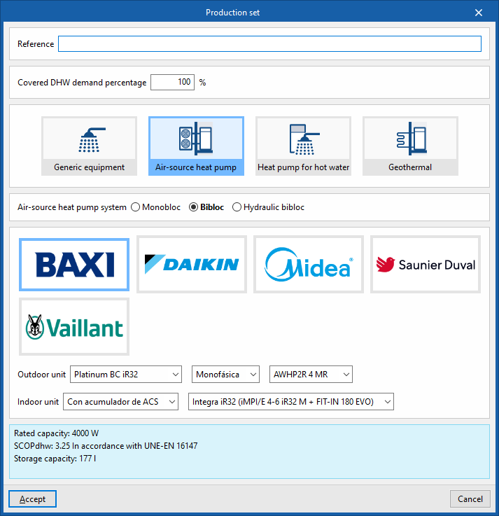
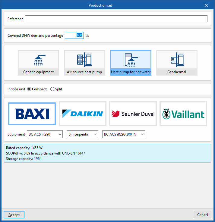
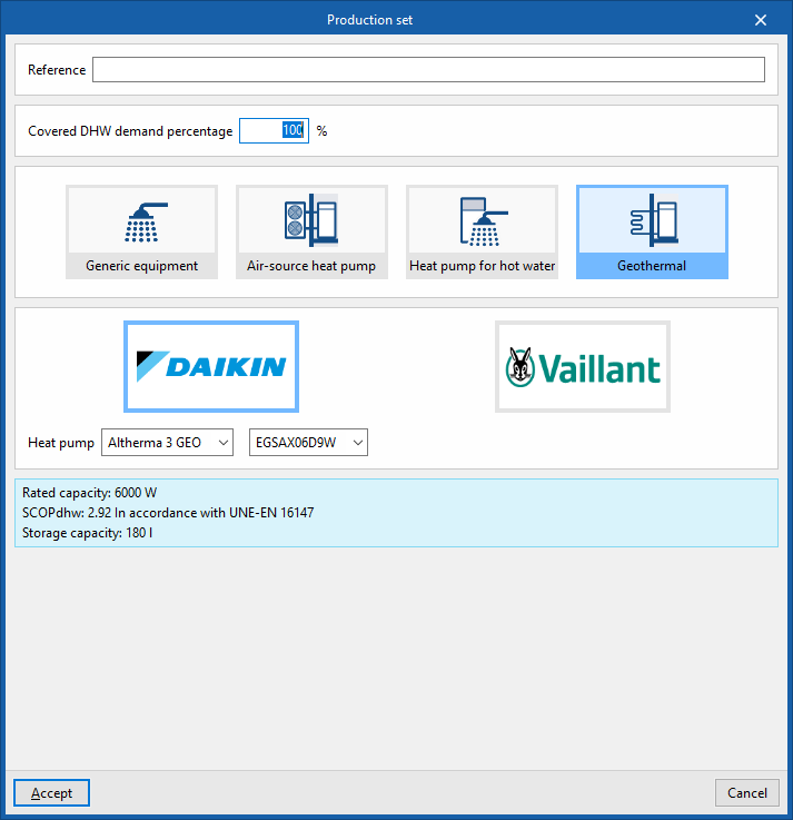
Equipment from manufacturers: air-source heat pumps, heat pumps for domestic hot water, ground-source heat pumps
The "Aerothermal", "Heat pump for DHW" and "Geothermal" options allow this type of equipment to be used to meet DHW demand and, under the logos of various manufacturers, offer the possibility of selecting equipment from their commercial catalogues. The specifications of this equipment are fully defined within the program based on the data provided by the manufacturers.
The options available in the editing panels are as follows:
- Connection to the Open BIM Database
Lets you sign in to the Open BIM Database. - Manufacturer selection
Select the desired manufacturer. - Import manufacturer data
This button, located on the right-hand side of the window, allows you to import equipment data from one of the available manufacturers by selecting the catalogue and the desired product.
DHW accumulator tanks
The "Accumulator tanks" section provides a list containing the definitions of the DHW accumulator tanks associated with the system, in order to account for their heat losses when calculating the energy demand for DHW. These heat losses will be offset by the set of production equipment defined within the DHW system.
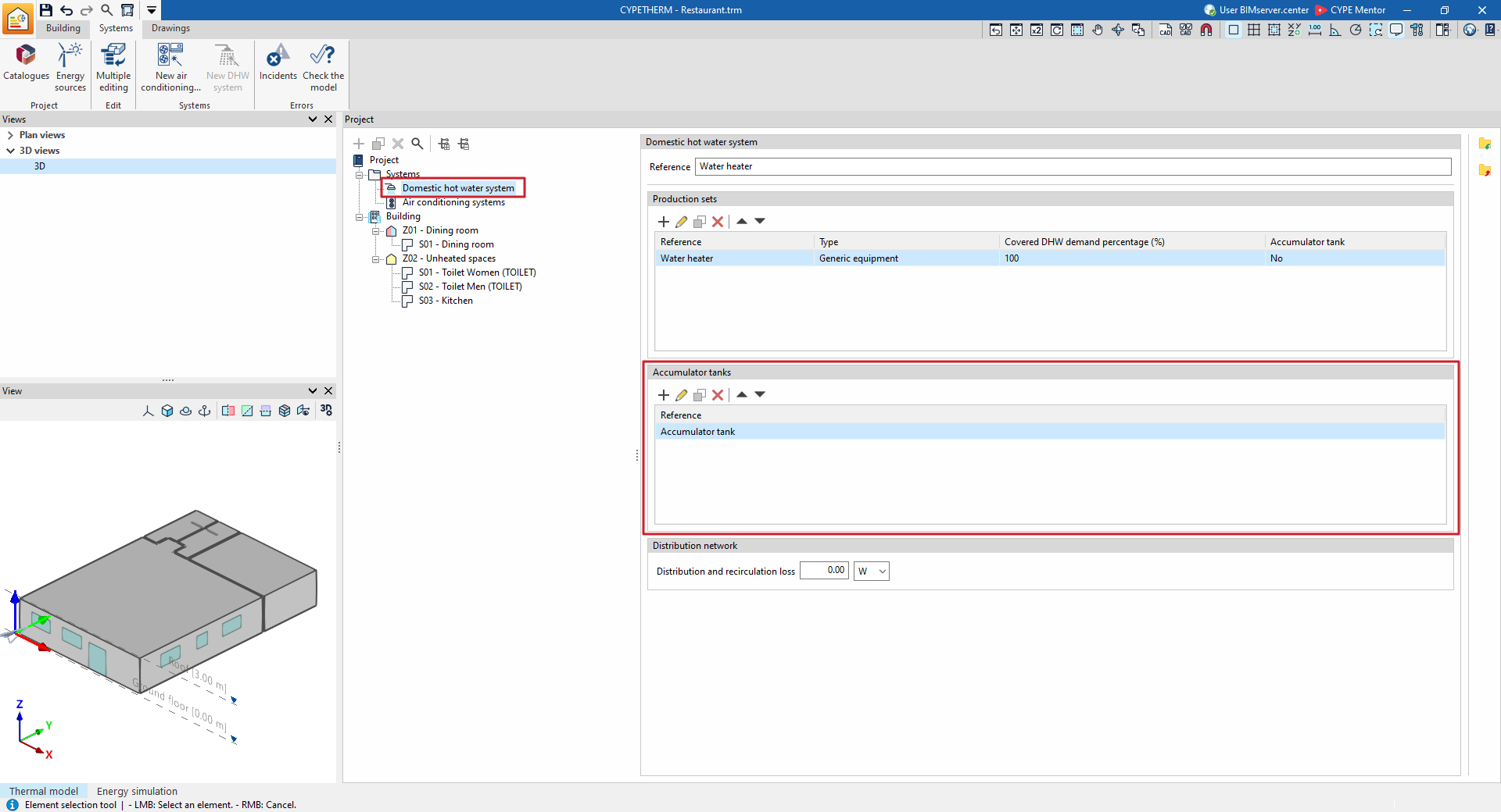
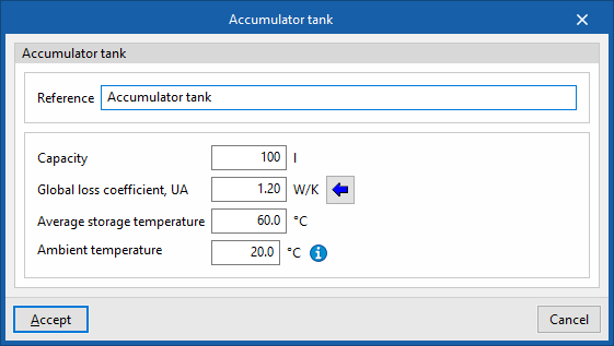
When entering or editing a DHW accumulator tank, the following parameters must be specified:
- Reference
- Capacity
Volume of the accumulator tank. - Global loss coefficient, UA
A wizard is provided to calculate the UA value of the accumulator tank based on the characteristics of its insulation, in accordance with the IDAE document "Technical guide: Design and analysis of thermal insulation for pipework, appliances and equipment".- Capacity
Volume of the accumulator tank, based on the figure entered on the previous screen. - Outer diameter
Outer diameter of the accumulator. - Insulation thickness
Insulation thickness in the accumulator tank casing. - Thermal conductivity of the insulation
This value can be imported from the material selected in the wizard on the right.
- Capacity
- Average storage temperature
The average temperature of the water stored in the unit. - Ambient temperature
The average ambient temperature of the room where the DHW accumulator tank is installed.
Distribution network
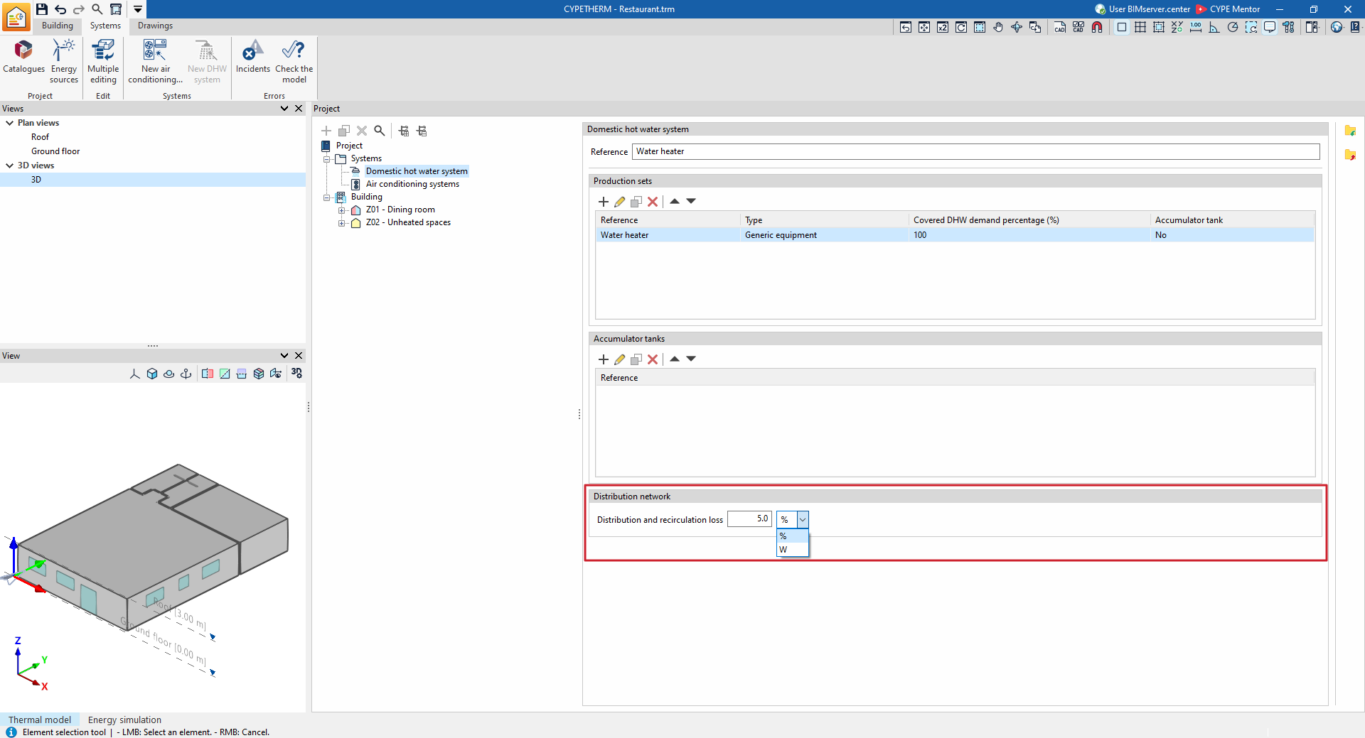
The "Distribution network" section allows you to define the distribution and recirculation losses associated with the DHW system, so that these can be taken into account when calculating the energy demand for DHW:
- Distribution and recirculation
losses: These losses may be defined as a constant value in watts (‘W’), or as a percentage (‘%’) of the DHW energy demand of the zones served by the DHW system.
Areas served
The "Zones served" section appears in the edit window for each DHW system if "Demand by heating zone" has been selected in the "General parameters", and allows you to select the heating zones served by the selected DHW system.
| Note: |
|---|
| An area can only be served by one DHW system. |