
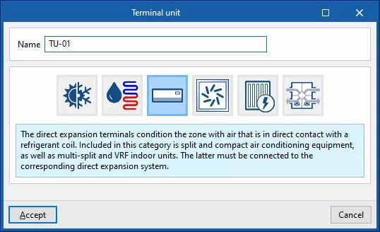
Terminal units. Direct expansion terminal unit
Direct expansion terminal units include the indoor units of 1x1 split systems, multi-split systems, variable refrigerant flow (VRF) systems, compact window units and water-to-air heat pumps (HP) in a loop configuration.
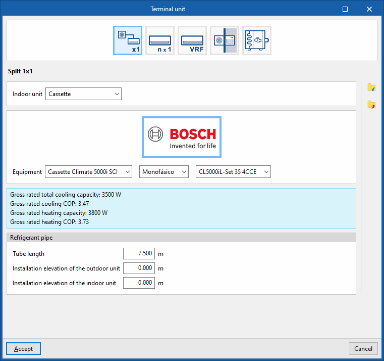
Split 1x1
Simulate a manufacturer’s 1x1 split system installed in the heating zone.
This category includes 1x1 split systems and 1x1 ducted systems. In the latter case, you don't need to model the ductwork network, as all ducts must lead to the same thermal zone. Furthermore, the program does not take heat losses in the ducts into account.
Indoor unit
In the drop-down menu, select whether the indoor unit is a "Cassette", "Wall-mounted", "Ceiling-mounted’, "Floor-standing" or "Ducted" unit.
The equipment must then be selected from the manufacturers and models available in the Open BIM Database, which have been downloaded beforehand from the "Catalogues" option on the main interface.
Refrigerant pipe
- Tube length
- Installation height of the outdoor unit
- Installation height of the indoor unit
| Note: |
|---|
| A 1x1 split is defined directly in the "Terminal units" section for each zone and does not require an air-conditioning system to be entered in the "Air-conditioning systems" section. |
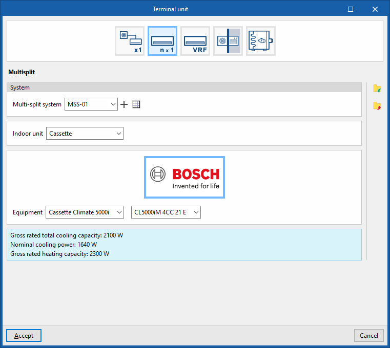
Multisplit
Simulate a manufacturer’s multi-split indoor unit installed in the thermal zone.
System
- Multi-split system
Select a multi-split system defined in the "Air-conditioning systems" section or enter one directly.
Indoor unit
In the drop-down menu, select whether the indoor unit is a "Cassette", "Wall-mounted", "Ceiling-mounted", "Floor-standing" or "Ducted" unit.
The equipment must then be selected from the manufacturers and models available in the Open BIM Database, which have been downloaded beforehand from the "Catalogues" option on the main interface.
Variable refrigerant flow (VRF)
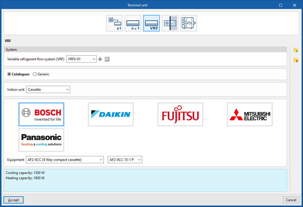
Simulate an indoor unit of a variable refrigerant flow system installed in the heating zone. You must select the "System" and specify whether the indoor unit is "Generic" or from one of the available manufacturer "Catalogues":
System
- Variable refrigerant flow (VRF) system
Select a variable refrigerant flow system as defined in the "Air-conditioning systems" section, or enter one directly.
Catalogues
In the drop-down menu, select whether the indoor unit is a "Cassette", "Wall-mounted", "Ceiling-mounted", "Floor-standing", "Ducted", "Air curtain" or "Water production" unit.
The equipment must then be selected from the manufacturers and models available in the Open BIM Database, which have been downloaded beforehand from the "Catalogues" option on the main interface.
Generic
Simulate a generic indoor unit in a variable refrigerant flow system and configure the following parameters:
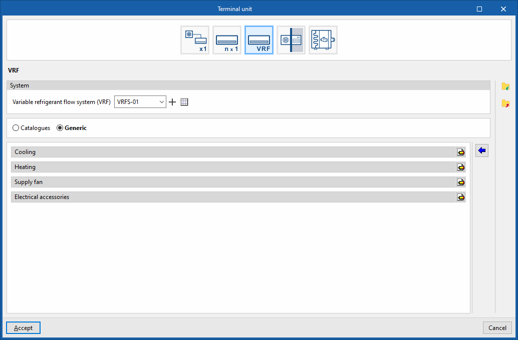
Cooling
- Cooling coil type (Variable refrigerant flow / None)
Adjusts the cooling coil characteristics:- Variable refrigerant flow
- Gross rated sensible heat ratio (optional)
- Gross rated total capacity (optional)
- Variable refrigerant flow
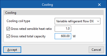
Heating
- Heating coil type (Variable refrigerant flow / None)
Adjusts the heat coil characteristics:- Variable refrigerant flow
- Gross rated capacity (optional)
- Rated total heating capacity sizing ratio
- Variable refrigerant flow
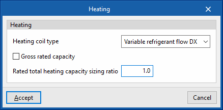
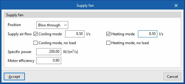
Supply fan
- Position (Blow through / Draw through)
- Supply air flow
- Cooling mode (optional)
- Cooling mode, no load (optional)
- Heating mode (optional)
- Heating mode, no load (optional)
- Specific power
- Motor efficiency
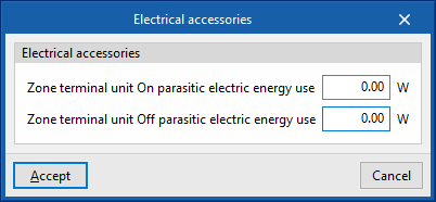
Electrical accessories
- Zone terminal unit On parasitic electric energy use
- Zone terminal unit Off parasitic electric energy use
Compact equipment
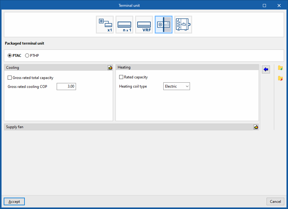
Simulate compact window units installed in the thermal zone. You must select whether it is a "A packaged terminal air conditioner (PTAC)” or a "Packaged Terminal Heat Pump (PTHP)":
A packaged terminal air conditioner (PTAC)
Simulate a compact window-mounted air-conditioning unit (PTAC) installed in the thermal zone and configure the following parameters:
Cooling
- Gross rated total capacity (optional)
- Nominal cooling COP
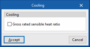
- Advanced settings:
- Gross rated sensible heat ratio
Heating
- Rated power (optional)
- Heat exchanger type (Electric / Hot water / Gas)
Adjust the heat exchanger settings:- Electric
- Hot water
- Hot-water system
Select a water-based heating system defined in the "Heating and cooling systems" section or enter one directly.
- Hot-water system
- Gas
- Gas heating coil efficiency
- Parasitic electric load
Supply fan
- Supply air flow
- Cooling mode (optional)
- Heating mode (optional)
- No load (optional)
- Position (Blow through / Draw through)
- Specific power
- Motor efficiency
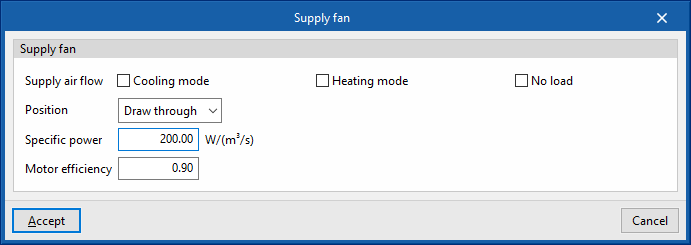
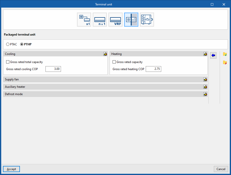
Compact heat pump unit (PTHP)
Simulate a compact window-type heat pump (PTHP) unit installed in the thermal zone and configure the following parameters:
Cooling
- Rated total power (optional)
- Nominal cooling COP
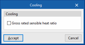
- Advanced settings:
- Gross rated sensible heat ratio
Heating
- Gross rated capacity (optional)
- Gross rated heating COP
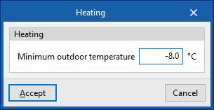
- Advanced settings:
- Minimum outdoor temperature
Supply fan
- Supply air flow
- Cooling mode (optional)
- Heating mode (optional)
- No load (optional)
- Position (Blow through / Draw through)
- Specific power
- Motor efficiency
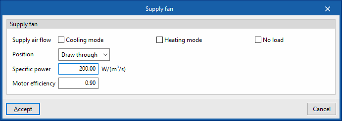
Auxiliary heater
- Rated capacity (optional)
- Maximum outdoor temperature
- Heating coil type (Electric / Hot water / Gas)
Adjust the heat exchanger settings:- Electric
- Hot water
- Water-based heating system
Select a water-based heating system defined in the "Heating and cooling systems" section or enter one directly.
- Water-based heating system
- Gas
- Gas heating coil efficiency
- Parasitic electric load
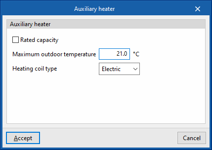
Defrost mode
- Defrost method (Resistive / Reverse cycle)
- Resistive defrost heater capacity
- Defrost mode maximum outdoor temperature
- Control (Timed / On-demand)
- Heat pump defrost time period fraction
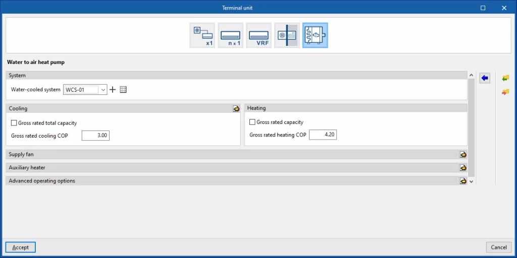
Water-to-air heat pump
Simulate a water-to-air heat pump (HP) in a loop configuration within the heating zone and configure the following parameters:
System
- Water-cooled system
Select a water-cooled condensing system defined in the "Air-conditioning systems" section or enter one directly.
Cooling
- Gross rated total capacity (optional)
- Nominal cooling COP
- Advanced settings:
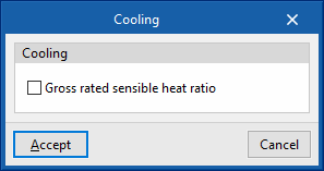
- Gross rated sensible heat ratio
Heating
- Gross rated capacity (optional)
- Gross rated heating COP
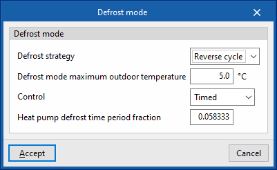
Supply fan
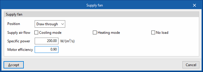
- Position (Draw through / Blow through)
- Supply air flow
- Cooling mode (optional)
- Heating mode (optional)
- No load (optional)
- Specific power
- Motor efficiency
Auxiliary heater
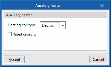
- Heating coil type (Electric / Hot water)
Adjust the heat exchanger settings:- Electric
- Rated capacity (optional)
- Hot water
- Hot-water system
Select a water-based heating system defined in the "Heating and cooling systems" section or to enter one directly.
- Hot-water system
- Electric
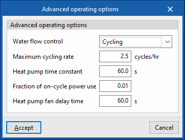
Advanced operating options
- Water flow control (Constant / Cycling / Constant on demand)
- Maximum cycling rate
- Heat pump time constant
- Fraction of on-cycle power use
- Heat pump fan delay time