Generating native Revit elements from an IFC file of piping systems
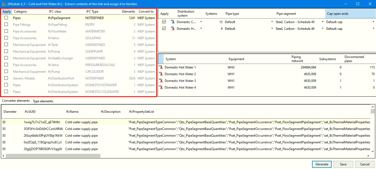
The "Generation of native Revit elements" module includes the feature "Generation of native Revit elements from an IFC of piping systems". This feature allows the conversion of an MEP model (included in a BIMserver.center project) to native Revit piping systems by assigning families.
You can generate complete pipe systems, including not only systems, pipes and joints, but also pipe insulation, equipment and pipe fittings.
| Best practice: |
|---|
| When generating native Revit elements from an IFC file of piping systems, it is essential to work with a Revit file that uses the systems template. This ensures correct import and better integration of the elements into the model. In addition, it is useful to define the "Discipline" property as "Coordination" in the view, from the "Properties" palette. |
| Note: |
|---|
| To convert piping systems (generated in CYPEPLUMBING) to native Revit entities, you must select the following checkboxes in CYPEPLUMBING, under the "Share" option in the "BIMserver.center" menu: "Water Systems" or "Sanitary Systems". If sharing from CYPEFIRE Hydraulic Systems, it is essential to activate "Export connection ports" so that the information on the inlet and outlet ports of the installation elements is incorporated, allowing the different piping systems to be distinguished and connected. |
How the "Generation of native Revit elements based on a structural IFC" module works
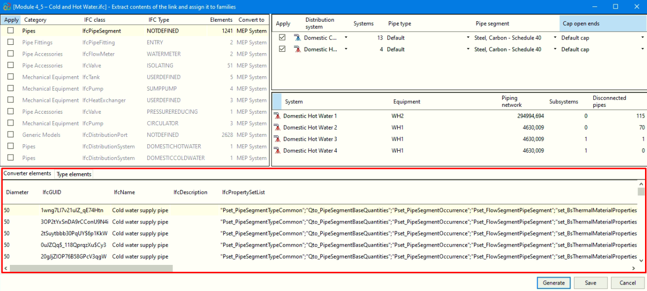
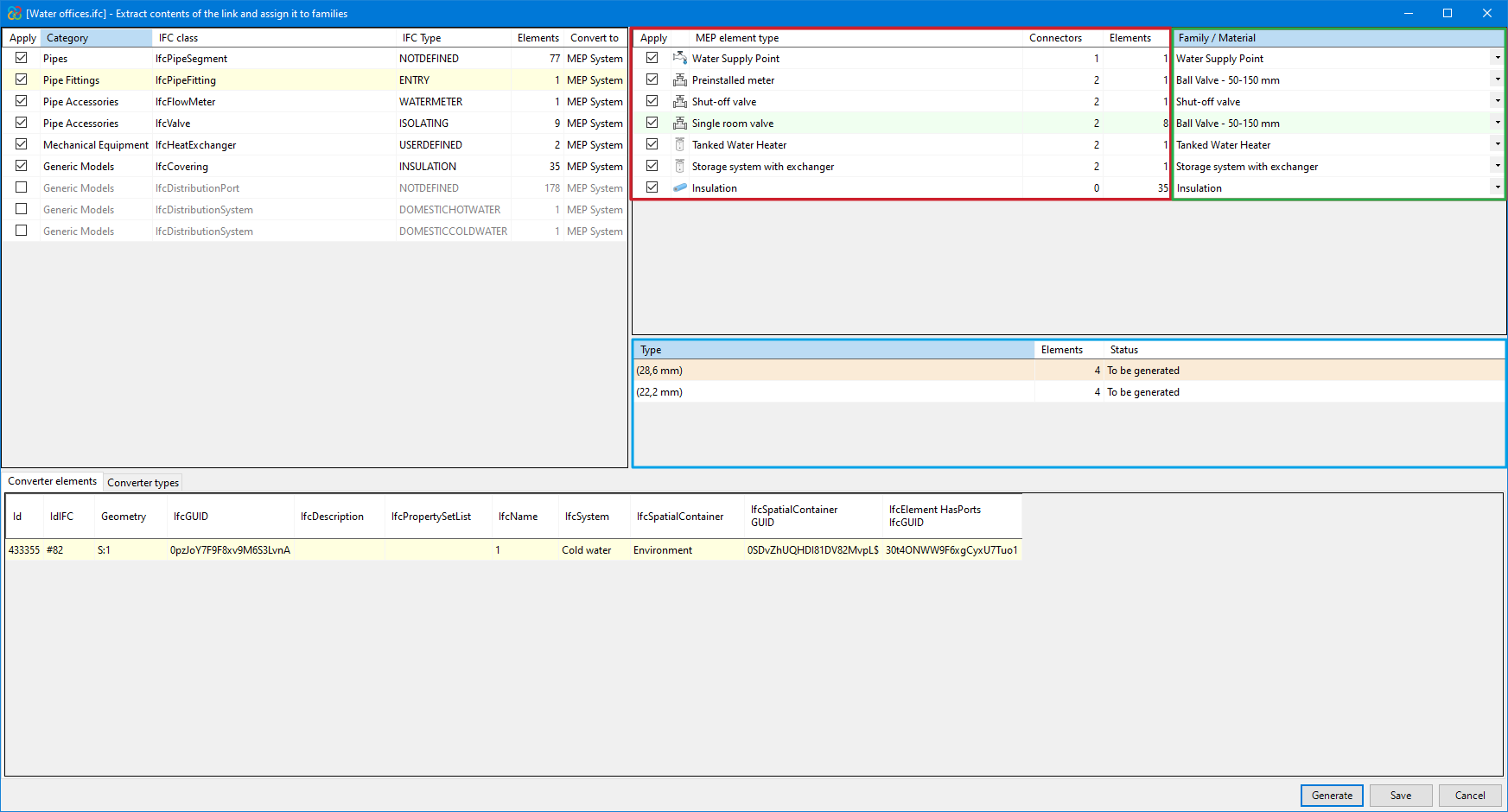
After selecting the "Extract contents of the link and assign it to families" option a dialogue box with the same name opens. This is how it works:
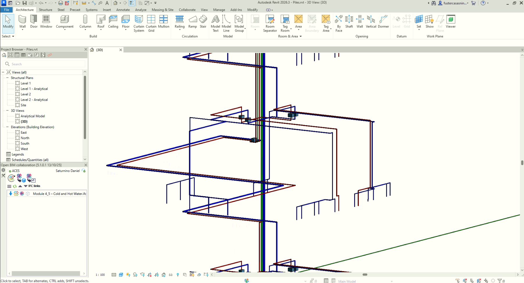
- Main section
- All categories of structural elements detected in the IFC links of the imported model are shown at the top left-hand side and are grouped by class and the IFC type to which they belong. The number of existing instances and the Revit native category to which they are to be converted are also displayed from these groups.
- The categories (along with their IFC class) that can be detected and converted to native elements within Revit are:
- Pipes - IfcPipeSegment
- Pipe connections - IfcPipeFitting
- Pipe fittings - IfcFlowMeter, IfcValve
- Mechanical equipment - IfcTank, IfcPump, IfcHeatExchanger
- Generic models - IfcCovering
- Revit native family selector (Converter)
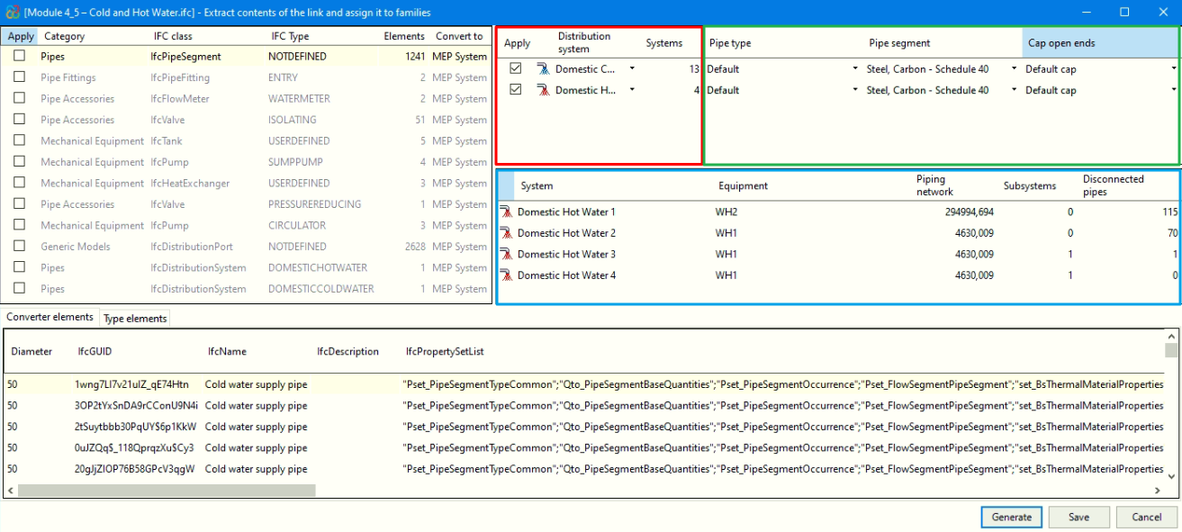
A) For the category "Pipes":
- In the upper right-hand corner, in the area framed in red in the image, the distribution systems for the category selected in the "Main section" are grouped together, along with the corresponding quantity.
- For these systems, from the area marked in green in the image, you can assign an existing pipe type in the Revit model to convert to native elements. In addition, the type of pipe segment must be selected and, if you wish to plug the ends, indicate the corresponding plug type.
- The central table, framed in blue in the image, shows the items from the distribution system selected in the table immediately above.
B) For all other categories:
- In the upper right-hand corner, in the area framed in red in the image, the MEP elements in the category selected in the "Main section" are grouped together, along with the corresponding quantity.
- For these elements, from the area framed in green in the image, you can:
- Assign previously loaded families in the Revit model.
- Generate parametric families, according to the type of element:
- In the case of valves, families are generated with standard valve geometry.
- In the case of insulation (in pipes and pipe joints), it is necessary to select a material preloaded in the Revit model.
- In the remaining elements, families are generated from the geometry contained in the IFC entities.
- The central table, framed in blue in the image, shows the types of the selected family in the upper green box.
- When you select generate families, the types will appear with the label "To be generated", as no type has yet been created for that family.
- If you choose to assign an existing family, the required types that are already defined in that family will appear with the label "Existing", while the required types that are not found in it will be displayed with the label "To be generated".
| Note: |
|---|
| When generating families or assigning an existing family, the remaining necessary types will be automatically created, identified by the diameter in brackets in their name. |
- Converter instances
At the bottom of the "Extract link content and assign to families" dialogue box, information about all converter instances is displayed.