
Punching shear verification
Once the data has been introduced, the viewed support can be checked on-screen using the Check option in the General data menu.
Analysis carried out
The program carries out the punching shear check using the following steps:
- Critical punching shear area
Obtains and marks on-screen, the worst case critical punching shear area around the support, defined by its critical perimeter. - Worst case forces
Obtains the worst case forces transmitted by the floor slab to the support along the punching shear surfaces. - Stress calculation
Calculates the stresses along the critical perimeter and compares them to the stress resistance of the concrete. - Check of the provided punching shear reinforcement
If users introduce additional punching shear reinforcement, the program verifies the behaviour of the reinforcement distribution in accordance with the selected code.
On-screen results and reports
Using the Check option in the General data menu, the following results can viewed on-screen or in a report:
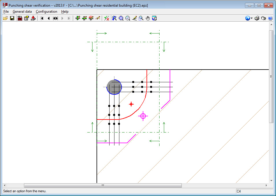
- Verification critical perimeter (red)
- Perimeter adjacent to the support (blue)
- External perimeter of the reinforcement (magenta) if punching shear reinforcement is provided.
Displayed with these perimeters is their centre of gravity with its corresponding colour.
The reports display all the checks carried out on the geometric and resistance specifications, and that the reinforcement distribution is in accordance with the selected code.
When the Check option in the General data menu, the program asks "Would you like to view the complete report of the assessed checks?". If the answer is yes, the report will be displayed on-screen and can be printed or exported to various formats. Only the report of the support currently viewed on-screen will be exported or printed.
To obtain the verification reports of all the supports of the job in a single document, the Job report option must be selected (File > Print).
Drawings
Using the Job drawing option (File > Print), users can configure and generate drawings of all the supports of the job. These drawings display the details of the selected reinforcement and its take-off.