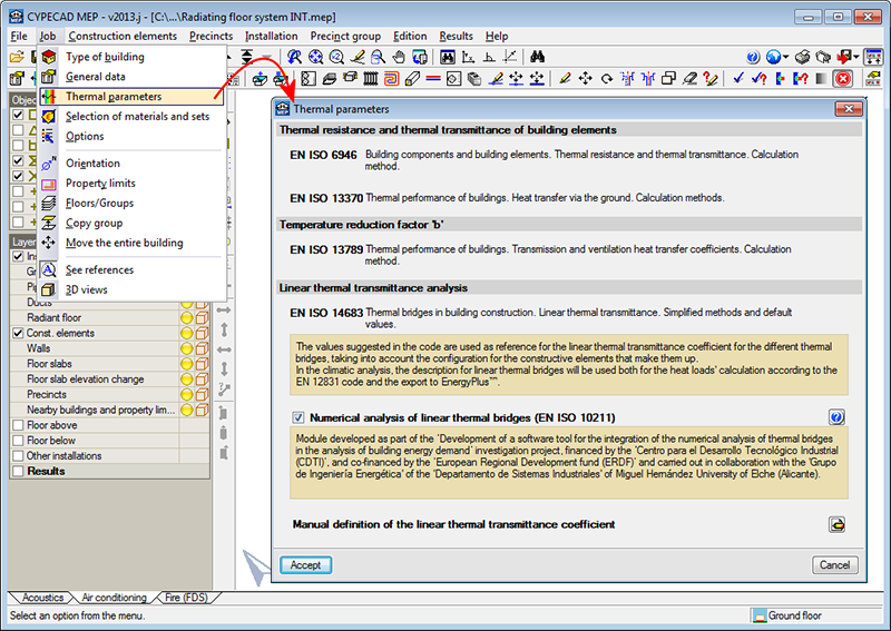
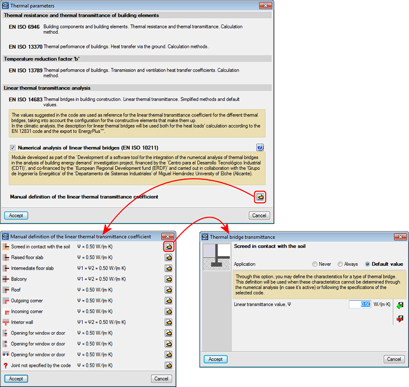
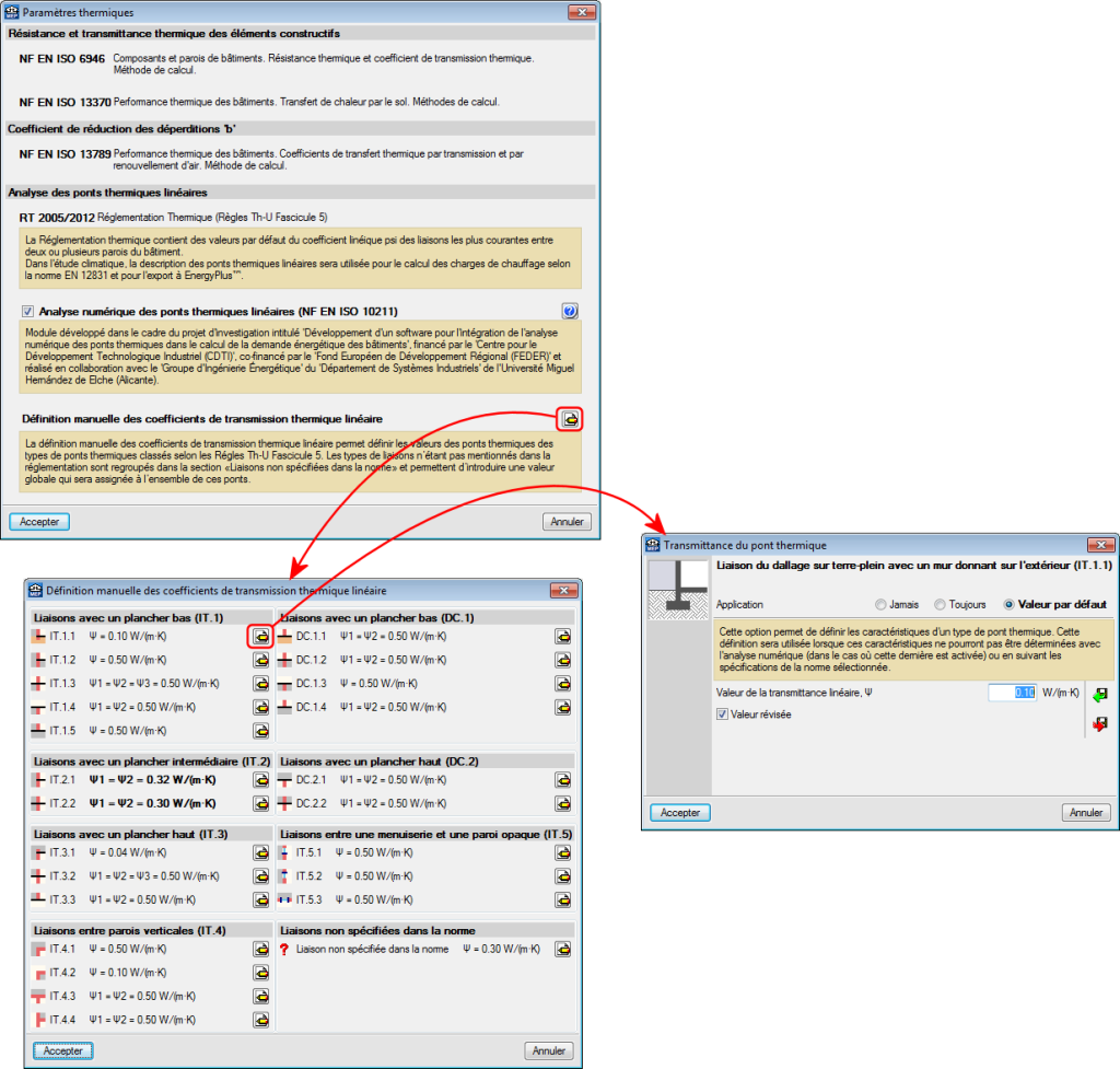
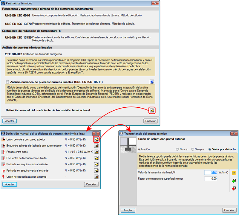
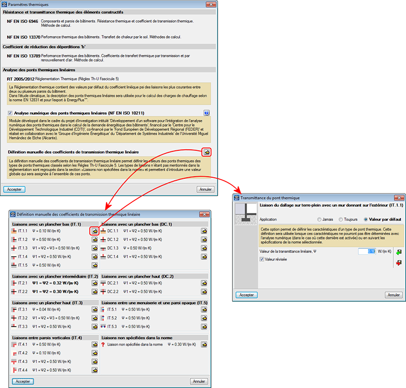
A new dialogue box has been implemented to manage the characteristic heat transmission parameters; the Thermal parameters dialogue box. This box can be accessed from the Air conditioning tab (Job > Thermal parameters).
This new dialogue box offers users information on the codes applied when analysing the various characteristic heat transmission parameters and allows users to manage the different options of by the program for their analysis. The appearance of this dialogue box depends on the on the language which CYPECAD MEP has been executed with (English, French, Portuguese, Portuguese for Brazil, Spanish, Spanish for Argentina and Spanish for Mexico). For the Catalan version, the dialogue box has the same aspect as with the Spanish version.
In previous versions, users could manage, in a collective manner for the detected types of linear thermal bridges, the type of analysis or which heat transmission coefficients were to be applied at the edges of these thermal bridges. Now, with the Thermal parameters dialogue box, users can configure and specify the analysis method to calculate the linear transmittance of each linear thermal bridge.
Amongst the options included in the Thermal parameters dialogue box is the option to activate the design using the numerical analysis of linear thermal bridges and the option to define user values for the various types of linear thermal bridges.
As of previous versions, the program automatically detected the different intersections (edges) between construction elements, where linear thermal bridges could emerge. Now, the heat transmission coefficient in these edges can be obtained in four different ways depending on the data that has been introduced in the new Thermal parameters dialogue box and for each type of linear thermal bridge:
- By assigning values proposed by the reference design code
The values proposed by the reference code are assigned. The reference code depends on the country that has been selected upon creating a new job. - By manually defining its properties
These are defined using the button (Manual definition of the linear thermal transmittance coefficient) in the “Thermal parameters” dialogue box. Upon selecting the option, a dialogue box opens where users can choose amongst three options to define the linear transmittance of each type of thermal bridge:
- Never
The thermal properties of the selected linear thermal bridge are not considered. - Always
Always consider the thermal properties defined for the selected thermal bridge. - Default value
The thermal properties defined for the selected linear thermal bridge will be used in the analysis if it has not been possible to establish them using the numerical analysis (if activated) or following the specifications of the reference code used.
- Never
- Using the Numerical analysis of linear thermal bridges module
Once the construction elements have been introduced in CYPECAD MEP, the program automatically identifies the thermal bridges of the thermal envelope of the building when the analysis is launched (Results > Analyse). The Numerical analysis of linear thermal bridges module calculates the thermal bridges it detects if the Numerical analysis of linear thermal bridges option has been activated in the General data dialogue box (Job > General data). - By introducing a Floor slab thermal break
Floor slab thermal breaks can be introduced in the floor slabs (Construction elements > Floor slab thermal break or using the button). This way, the continuity of the insulation is assured at the thermal bridges of the slab and the energy consumption of the building is limited. Users introduce a thermal break, on plan, at the edge of the slab (where a thermal bridge is present), indicating the initial and final points of the break and its linear transmittance. The program detects the break and substitutes the transmittance of the thermal bridge with the transmittance defined in the break.
Within the Thermal parameters dialogue box, users can define different analysis methods or assign values for the thermal parameters for a type of linear thermal bridge. To avoid duplicating, the program follows a priority order to assign the thermal parameters when calculating the heat transmission via a thermal bridge:
- Presence of thermal breaks
If the user has defined thermal breaks, its thermal parameters are used to calculate the transmission via the thermal bridge where it has been defined. - Manually introduced value using the “Always” or “Never” option
These values can be defined for each type of thermal bridge in the “Thermal parameters” dialogue box (Thermal parameters > Manual definition of the linear thermal transmittance coefficient > button >
  button of a specific type of thermal bridge > select “Always” or “Never” > introduction of the thermal parameters).
 - Value calculated using the numerical analysis of linear thermal bridges
If this module has been activated, the analysis will be for the set of thermal bridges it analyses. - Value obtained using the reference code
The reference code depends on the country that is selected when a new job is created. - Manually introduced value using the “Default value” option
These values can be defined for each type of thermal bridge in the “Thermal parameters” dialogue box (Thermal parameters > Manual definition of the linear thermal transmittance coefficient > > button
  button of a specific type of thermal bridge > select “Default value” > introduction of the thermal parameters).

