Terminal units. Direct expansion terminal units
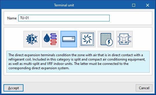
Direct expansion terminal units include the interior units of 1x1 split systems, multisplit systems, variable refrigerant flow (VRF) systems, compact window units and water-to-air heat pumps in a closed loop.
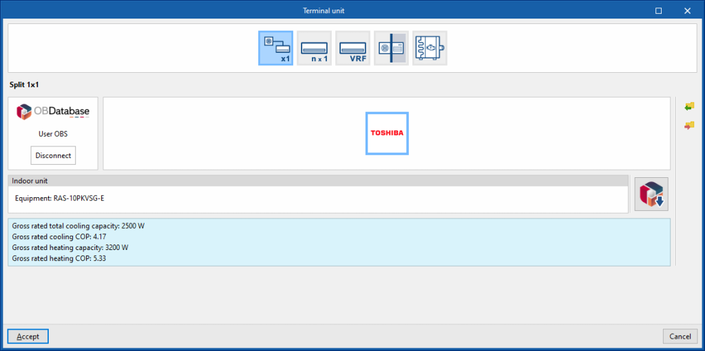
Split 1x1
This includes 1x1 split units and 1x1 ducted units. In the latter case, there is no need to simulate the duct network because all ducts must lead to the same heating zone. Furthermore, heat losses in the ducts are not considered in the program.
Manufacturer
This is used to simulate a manufacturer's 1x1 split system in the thermal zone.
Indoor unit
- Open BIM Database indoor unit selection
Allows users to select a 1x1 split indoor unit from the manufacturers and models available in the Open BIM Database.
Multisplit
Manufacturer
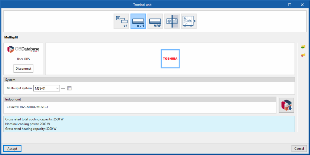
Allows users to simulate a manufacturer's multi-split indoor unit in the thermal zone.
System
- Multisplit system
Allows users to select a multisplit system defined in the "Air conditioning systems" section or to enter it directly.
Indoor unit
- Selecting the Open BIM Database indoor unit
Allows users to select a multisplit indoor unit from the manufacturers and models available in the Open BIM Database.
Variable refrigerant flow (VRF)
Generic
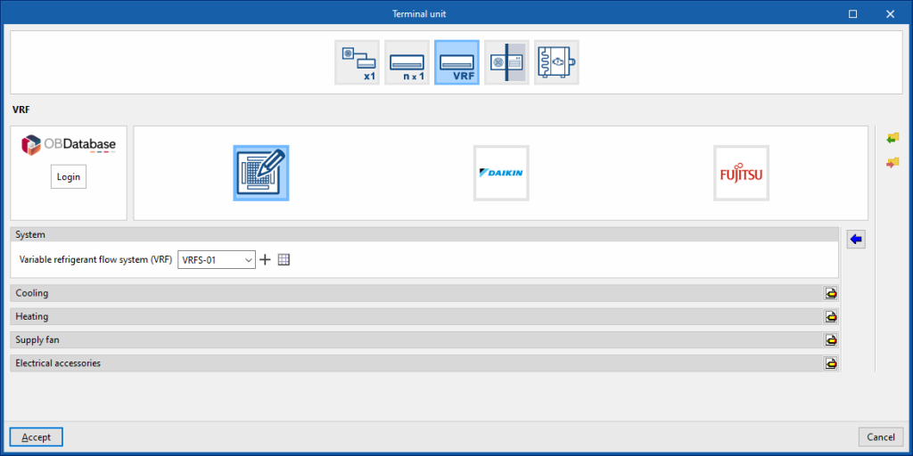
This allows users to simulate an indoor unit of a generic variable refrigerant flow system placed in the thermal zone.
System
- VRF
Allows users to select a VRF system defined in the "Air conditioning systems" section or to enter it directly.
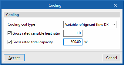
Cooling
- Cooling coil type (Variable refrigerant flow / None)
Sets the characteristics of the cooling coil:- Variable refrigerant flow
- Gross rated sensible heat ratio (optional)
- Gross rated total capacity (optional)
- Variable refrigerant flow
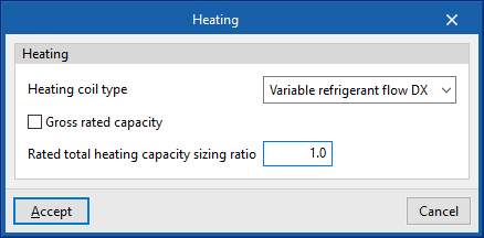
Heating
- Heating coil type (Variable refrigerant flow / None)
Sets the characteristics of the heating coil:- Variable refrigerant flow
- Gross rated capacity (optional)
- Rated total heatinc capacity sizing ratio
- Variable refrigerant flow
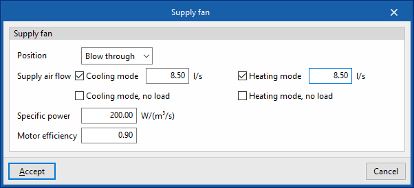
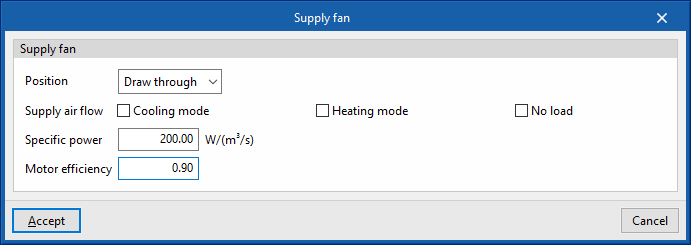
Supply fan
- Position (Blow through / Draw through)
- Supply air flow
- Cooling mode (optional)
- Cooling mode, no load (optional)
- Heating mode (optional)
- Heating mode, no load (optional)
- Specific power
- Motor efficiency
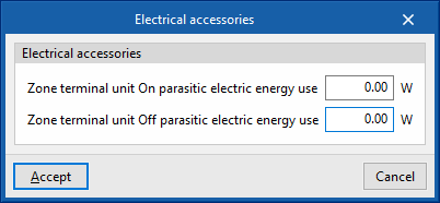
Electrical accessories
- Zone terminal unit On parasitic electric energy use
- Zone terminal unit Off parasitic electric energy use
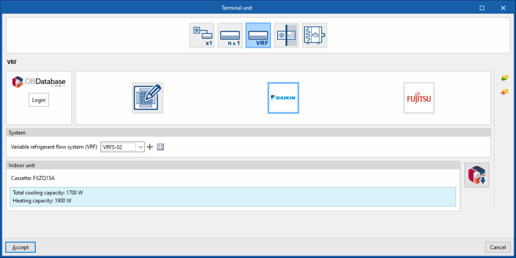
Manufacturer
This is used to simulate an indoor unit of a manufacturer's variable refrigerant flow system in the thermal zone.
System
- Variable refrigerant flow system (VRF)
Allows users to select a variable refrigerant flow rate system defined in the "Air conditioning systems" section or enter it directly.
Indoor unit
- Open BIM Database indoor unit selection
Allows users to select an indoor unit of a variable refrigerant flow system from the manufacturers and models available in the Open BIM Database.
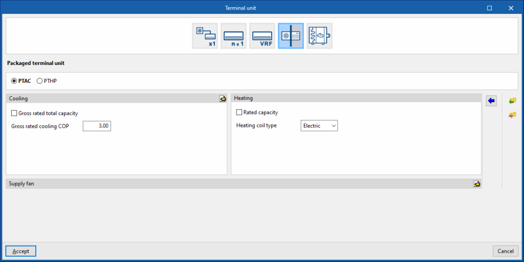
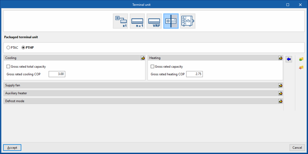
Packaged terminal unit
This allows users to simulate packaged window terminal units arranged in the thermal zone.
PTAC
Cooling
- Gross rated total capacity (optional)
- Nominal cooling COP
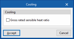
- Advanced configuration
- Gross rated sensible heat ratio
Heating
- Gross rated capacity (optional)
- Heating coil type (Electrical / Hot water / Gas)
This sets the characteristics of the heating coil:- Electrical
- Hot water
- Hot-water system
Allows users to select a water heating system defined in the "Air conditioning systems" section or to enter it directly.
- Hot-water system
- Gas
- Gas heating coil efficiency
- Parasitic electric load
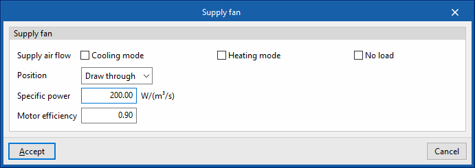
Supply fan
- Supply air flow
- Cooling mode (optional)
- Heating mode (optional)
- No load (optional)
- Position (Blow through / Draw through)
- Specific power
- Motor efficiency
PTHP
Cooling
- Gross rated total capacity (optional)
- Nominal cooling COP
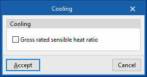
- Advanced configuration
- Gross rated sensible heat ratio
Heating
- Gross rated capacity (optional)
- Gross rated heating COP
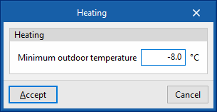
- Advanced configuration
- Minimum outdoor temperature
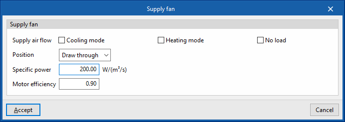
Supply fan
- Supply air flow
- Cooling mode (optional)
- Heating mode (optional)
- No load (optional)
- Position (Blow through / Draw through)
- Specific power
- Motor efficiency
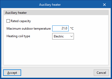
Auxiliary heater
- Gross rated capacity (optional)
- Maximum outdoor temperature
- Heating coil type (Electrical / Hot water / Gas)
Sets the characteristics of the heating coil:- Electric
- Hot water
- Hot-water system
Allows users to select a water heating system defined in the "Air conditioning systems" section or to enter it directly.
- Hot-water system
- Gas
- Gas heating coil efficiency
- Parasitic electric load
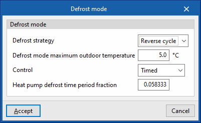
Defrost mode
- Defrost strategy (Resistive / Reverse cycle)
- Resistive defrost heater capacity
- Defrost mode maximum outdoor temperature
- Control (Timed / On demand)
- Heat pump defrost time period fraction
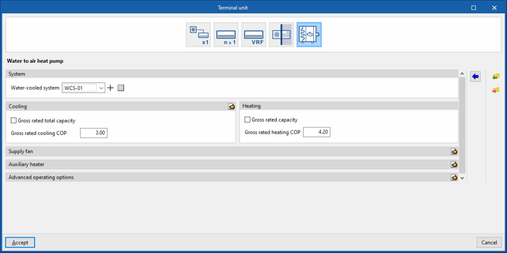
Water to air heat pump
System
- Water-cooled system
Allows users to select a water-cooled system defined in the "Air conditioning systems" section or to enter it directly.
Cooling
- Gross rated total capacity (optional)
- Nominal cooling COP
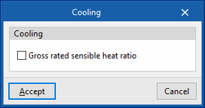
- Advanced configuration
- Gross rated sensible heat ratio
Heating
- Gross rated capacity (optional)
- Gross rated heating COP
Supply fan
- Position (Blow through / Draw through)
- Supply air flow
- Cooling mode (optional)
- Heating mode (optional)
- No load (optional)
- Specific power
- Motor efficiency
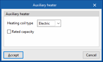
Auxiliary heater
- Heating coil type (Electric / Hot water)
Sets the characteristics of the heating coil:- Electric
- Gross rated capacity (optional)
- Hot water
- Hot-water system
Allows users to select a water heating system defined in the "Air conditioning systems" section or to enter it directly.
- Hot-water system
- Electric


