Air discharge
When a discharge grille is introduced (Ducts > Straight duct), a snap point appears on the indoor VRF units with duct distributions on the current floor.
This point is the starting point of the discharge duct that joins the indoor unit with the rooms it provides air to. This way, the program automatically distributes the loads of those rooms and the air flow moved by the unit, between the grilles and diffusers of the discharge duct.
- Load distribution
When the project is analysed, the thermal loads of the rooms connected to the indoor unit with the discharge grille are transferred to the indoor machine. The program takes into account the following configurations:
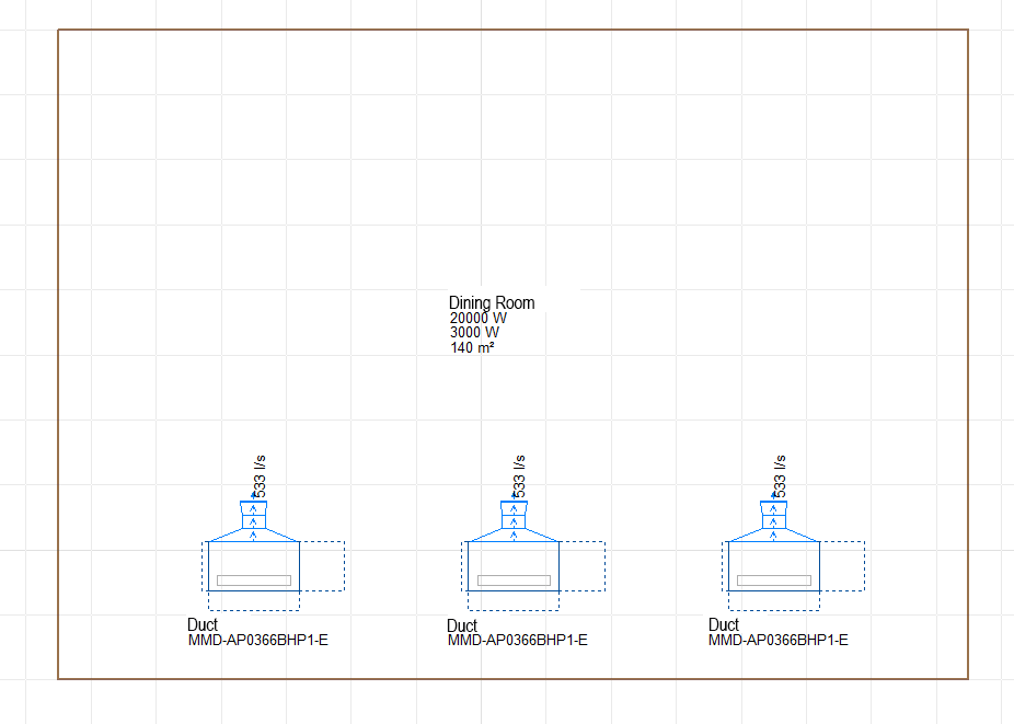
- Several machines providing air to the same room
The program will distribute the load equally for each machine. - One machine providing air to several rooms
The load assigned to the machine will be the sum of all the rooms. - There is another system in the room
If another system exists in the room to which the VRF unit provides air, e.g. a radiator, the load assigned to the machine will be the remaining load (the room load minus the radiator load), as long as the “Simultaneous” option has been selected in “General settings > Distribution of the thermal load of the precincts amongst the systems”.
- Several machines providing air to the same room
- Air flow distribution
When the air flow that is moved by the machine is calculated, it is shared amongst the grilles and diffusors of the discharge duct. The program takes different configurations into account:
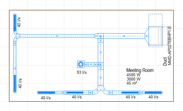
- One machine that provides air to several diffusors and grilles in the room
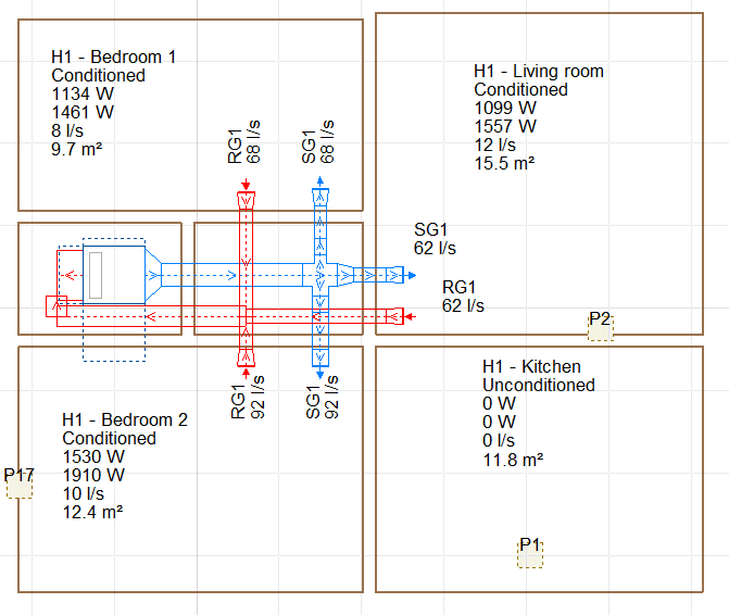
In this case, the program will divide the flow between them. If users set the flow of a grille or diffuser at a specific value, the remaining flow moved by the machine will be shared amongst the grilles and diffusors that do not have a set flow value. - One machine that provides air to several rooms
This is the usual case in dwellings. The discharge flow is shared amongst the discharge duct grilles depending on the cooling load of each room.
- One machine that provides air to several diffusors and grilles in the room
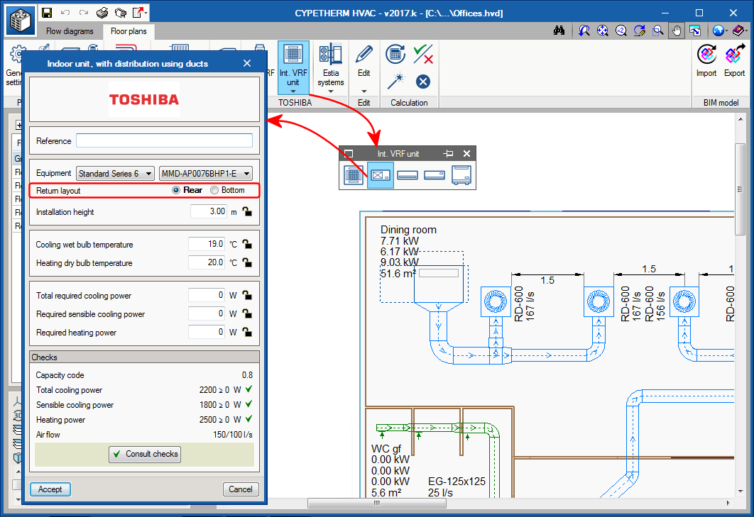
Air return
The configuration of the return position is defined directly in the panel of the indoor unit. There are two possible return positions:
- Rear
In this case a return duct network will have to be provided. - Bottom
It will be placed opening to a grille in the false ceiling without a return duct network.