As of the 2021.a version, CYPETHERM HVAC has been substituted by other design and Open BIM programs that as a whole have the capacities of CYPETHERM HVAC and whose evolution will improve the features of this program (more information).
As of the 2019.f version, CYPE programs (those downloaded from our website and those downloaded from the BIMserver.center platform) are compiled for 64-bit systems. The 64-bit compilation of CYPE software implies the use of the superior features of 64-bit processors and operating systems compared to those of 32 bits.

Please bear in mind that you must have a 64-bit operating system to be able to work with any 64-bit software.
In any case and as a temporary measure, the 2019.f version is available in 64 and 32 bits on the download area of our webpage. The programs that can be downloaded from the BIMserver.center platform are only available in 64 bits. If you have a 64-bit operating system, you can work with either the 64-bit and 32-bit version of our software, although we strongly recommend that you install the 64-bit CYPE software version.
You can see which operating system is installed on your computer by clicking on "Control panel > System".
Since 64-bit microprocessors began to be massively introduced into personal computers from 2003 and from the Windows XP version, Microsoft already offers the two versions of its operating systems (32 and 64 bits). We understand that almost all our users will have computers with 64-bit processors (x64) and 64-bit operating systems.
It could occur that a user may wish to work with a computer with a 64-bit processor but with a 32-bit operating system. It would be very strange if the computer had a 32-bit processor (x86 - computers over 15 years old). If any of these is your case, we advise you to talk to your hardware or software provider to update your situation as soon as possible. However, you can download the 32-bit version and work with CYPE programs that can be downloaded from our website until your situation is up-to-date.
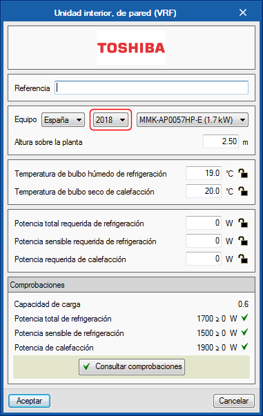
As occurs with CYPETHERM EPlus and CYPETHERM RECS Plus, some equipment of the Toshiba catalogue has been updated in the 2019.b version ofCYPETHERM HVAC. This equipment is shown as belonging to the 2018 category in the equipment selection panel.
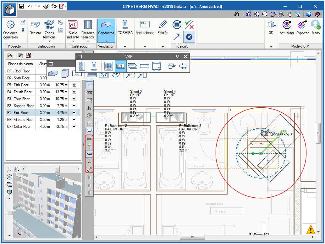
As of the 2019.a version, when an equipment unit is placed on the floor plan, a green line is included that emerges from it. When the unit is selected with the mouse cursor, a graduated circle appears that allows users to rotate the unit about itself. This rotation maintains a certain resistance at right-angles and at 45º.
As well as the graduated circle, when an equipment unit is introduced, a small menu appears with orange arrows (located between the plan view and the list of floor plans of the building) that allows for the unit to be introduced with a specific angle (the four right-angle positions or any selected angle) without the need to have to select the green line.
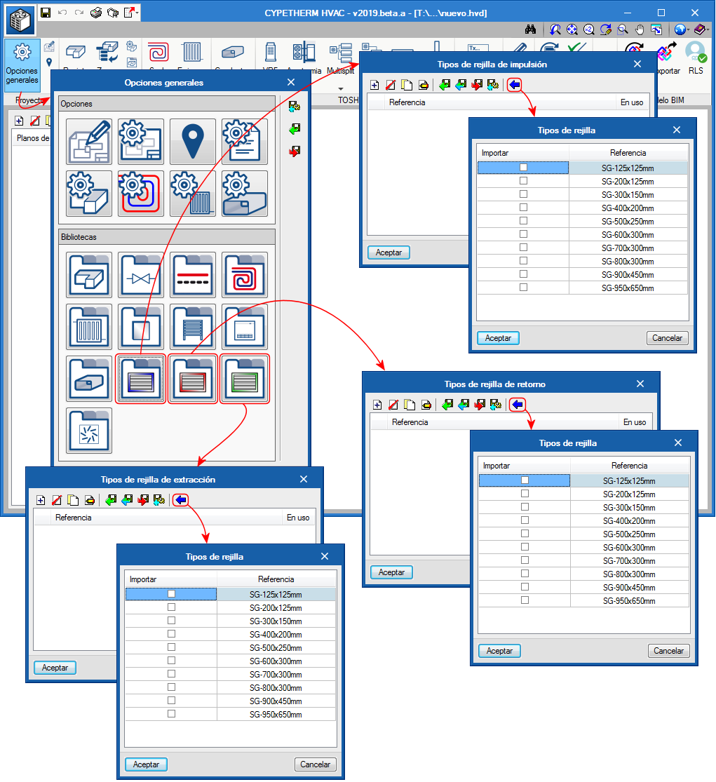
The 2019.a version of CYPETHERM HVAC includes three grilles libraries (discharge, return and extraction) that cover a range of flow rates from 25 to 1806 l/s. Each one can be imported once in the project that is being worked on. Additionally, all the elements that have not been used can be deleted from the project.
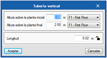
In order to introduce vertical spans of ducts and pipes, users must define:
- Height above the initial floor
- The initial floor (by selecting it from a drop-down button)
- Height over the final floor
- The final floor (by also selecting it from a drop-down button)
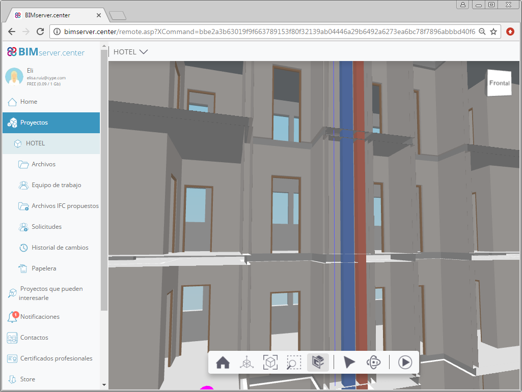
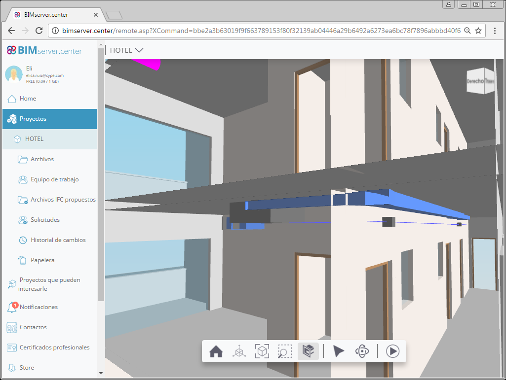
In previous versions, the elevation of the air conditioning installation equipment (VRF, Aerothermal, Multi-splits and Splits), ducts and pipes was defined. As of the 2019.a version, to indicate to the program the elevation above ground level of these elements, the "height above the ground" where they are located is indicated. This parameter appears in all the introduction dialogs of the mentioned equipment, ducts and pipes. This allows, for example, for several networks to be drawn on the same floor without colliding (for example: discharge and return ducts, and pipes).
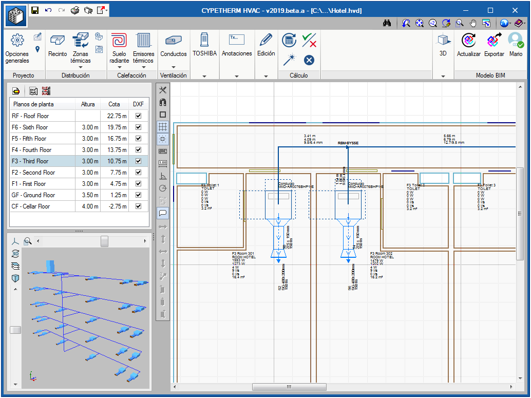
As of the 2019.a version, the analysis of all the systems that make up the air conditioning system is carried out entirely in CYPETHERM HVAC. Users must:
- Locate the indoor units
- Connect them by pipes to the outdoor unit
- Select "Analysis"
With the design process, CYPETHERM HVAC automatically performs the following tasks:
- Checks for design limitations
- Corrects power according to temperatures
- Checks models with thermal loads
- Selects the model for the outdoor unit
- Calculates the diameter of the pipes
- Generates a results report and the quantities of the installation.
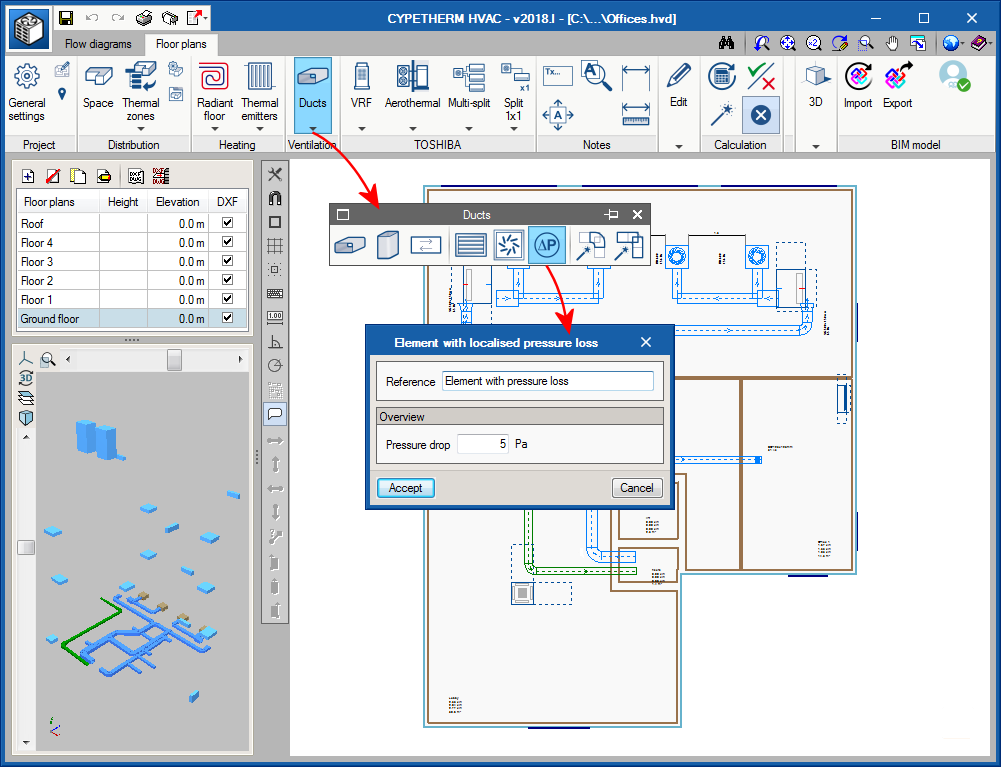
As of the 2018.l version, users can introduce an element with a localised pressure loss in the duct network to simulate the pressure loss that is generated by filters, dampers, etc.
This element is available in the “Ducts” section of the top toolbar, displayed using the “ΔP” icon.