New features

2019.a Version

5 June 2018
Index

New modules and programs

Open BIM Suspended ceilings (new program)

Open BIM Suspended ceilings is a free program created to design suspended ceilings of any type of building. It generates the layout of the suspended ceilings, which provides a valuable aid in their subsequent installation in the different rooms.

The program allows users to create a library of types of panels, it has a tool to automatically distribute the layout of the suspended ceilings, but also allows for them to be introduced manually, which is helpful for special cases.

An important aspect when carrying out the layout of the suspended ceilings is to locate where elements such as lights, air conditioning inlet and outlets or holes of the sprinkler system will be placed. Since "Open BIM Suspended ceilings" is integrated into the Open BIM workflow, it is able to read the requirements of openings of other programs included in that workflow, to include them in the final layout of the project. Furthermore, these programs, will also read the layout of the suspended ceilings provided by "Open BIM Suspended ceilings", which will allow them to visualize the panels and correctly place the elements.

"Open BIM Suspended ceilings" also generates the materials schedule of the suspended ceilings that have been placed and their quantities (including the calculation of the percentage loss of cut panels and holes) to export them to FIEBDC-3 format, that can be read by programs that manage bills of quantities.

Open BIM Suspended ceilings can be downloaded from the BIMserver.center platform.

More information on this new CYPE Open BIM program will be available shortly.

Post-tensioned waffle and joist floor slabs (CYPECAD module)

The CYPECAD module: "Post-tensioned waffle and joist floor slabs" allows users to design the passive reinforcement of waffle slabs, in-situ joist floor slabs and their perimeter beams, after calculating the forces of the post-tensioned tendons (adherent or non-adherent) and whose properties have been introduced by users.

This module allows users to introduce the layout of the tendons, their definition, stressing loads and percentage losses (instantaneous and deferred). The program generates two post-tensioned loadcases (one with instantaneous losses and the other with total losses: instantaneous + deferred) in which it will introduce the deviation loads that are produced due to the path of the tendons.

During the reinforcement design phase of the waffle slabs and, if the tendons have been defined as adherent, the contribution of the remaining or excess capacity of the active reinforcement is taken into account, which is subtracted to determine the passive reinforcement.

The functionality of the tools for introducing and editing bending lines and tendons is the same as for Post-tensioned slabs for building.

In order for CYPECAD to be able to carry out the indicated calculations for post-tensioned waffle slabs and joist floor slabs, the user license must include the permits for the “Post-tensioned waffle slabs and joist floor slabs” module.

StruBIM Anchors ACI 318 (new program)

StruBIM Anchors ACI 318 is a program designed to check concrete element anchors based on the ACI regulation (ACI 318-11 Annex D or ACI 318-14 Article 17). It checks cast-in, headed bolt anchors, L-bolt, J-bolt and bolts with their head welded to the plate, as well as post-installed anchors such as adhered anchors, undercut anchors, torque-controlled anchors with sleeves and headed stud anchors, and displacement-controlled anchors.

This application is integrated in the Open BIM workflow using the IFC standard. The program currently provides an IFC file to the BIM model that includes the check reports in PDF format.

StruBIM Anchors ACI 318 can be downloaded from the BIMserver.center platform.

CYPE Health and safety (new program)

CYPE Health and safety is a program created to assist users in the development of drawings of collective protection elements to be incorporated in the Health and Safety Project. It also exports the quantities of the introduced elements in FIEBDC-3 format to be treated by bill of quantity management programs.

With "CYPE Health and safety" users can define the construction phases of the project and include collective protection systems in each of them. The program allows users to define the following collective protection systems:

  • Railings and railing supports
  • Vertical nets and gibbet type supports
  • Floor slab openings protection
  • Storage zone
  • Risk indicator signs
  • Perimeter fence
  • Excavations
  • Accesses

CYPE Health and safety is integrated into the Open BIM workflow through the IFC standard. To be able to work with it, the project must be linked to a BIM project and the program will import the floor structure to generate a floor plan for each floor that has been imported from the project. In each floor plan, users must draw the safety elements that are to be included in the project.

To be able to work with CYPE Health and safety, users must have the required permits, which are the same that are required to access the "Collective protection systems" module of CYPECAD. This permit must be updated to the 2019.a version or later.

CYPE Health and safety can be downloaded from the BIMserver.center platform.

More information on this new CYPE Open BIM program will be available shortly.

Open BIM Switchboard (new program)

Open BIM Switchboard has been created to design the enclosures that are present in electrical installations (cabinets, panels, switchboards...).

In previous versions, CYPELEC REBT (Spain) and CYPELEC NF (France) contained tools to design these enclosures in the “Cuadros” and “Tableaux” tabs, respectively. As of the 2019.a version, these tabs have been eliminated from the aforementioned programs and have been implemented in “Open BIM Switchboard”.

In comparison to the “Cuadros” and “Tableaux” tabs of the previous CYPELEC REBT and CYPELEC NF versions, Open BIM Switchboard has the advantage of being integrated in the Open BIM workflow and the possibility to be used by users from other countries, since the program can be installed in English, French, Italian, Spanish, Catalan and Portuguese, and has an Open BIM connection with CYPELEC Core as well as with CYPELEC REBT and CYPELEC NF.

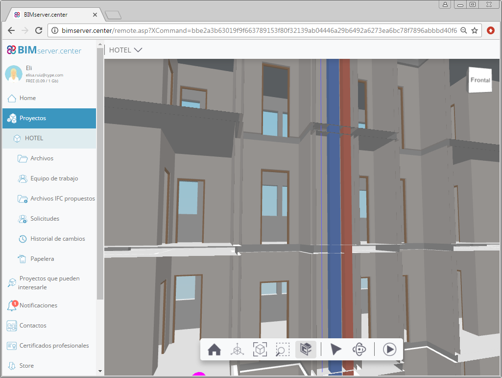
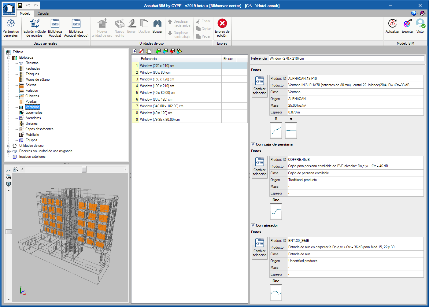
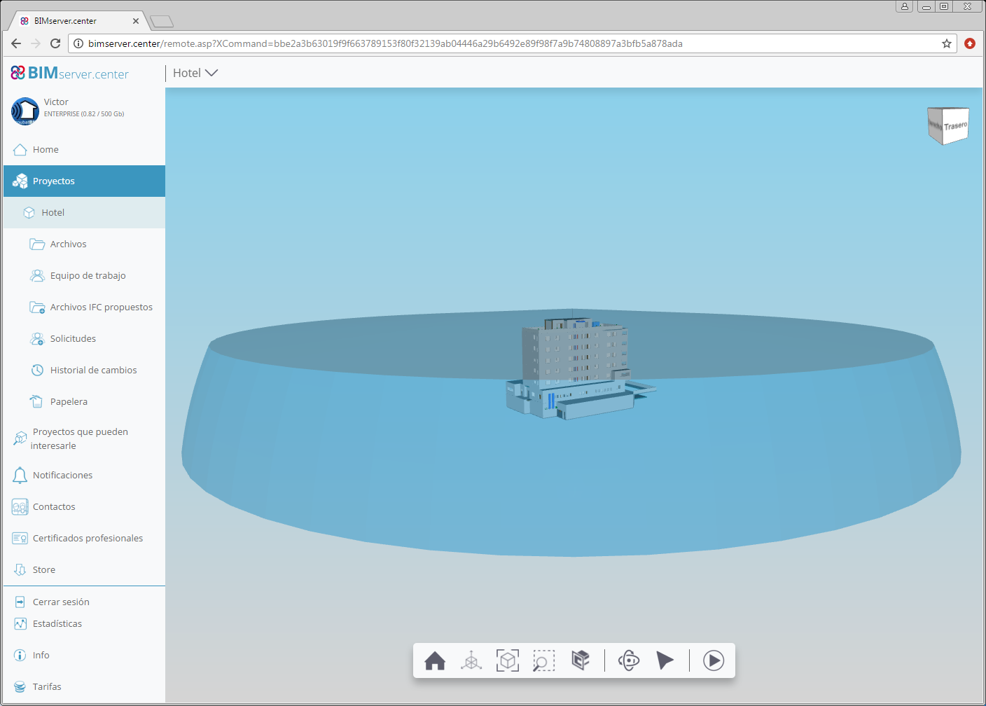
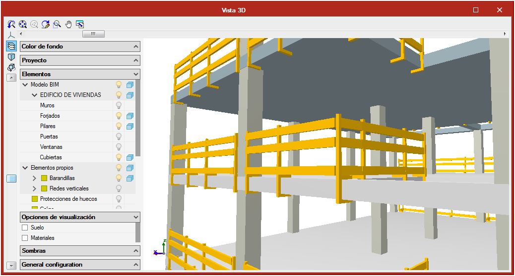
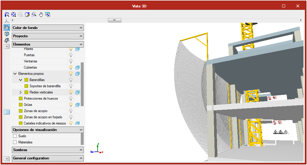
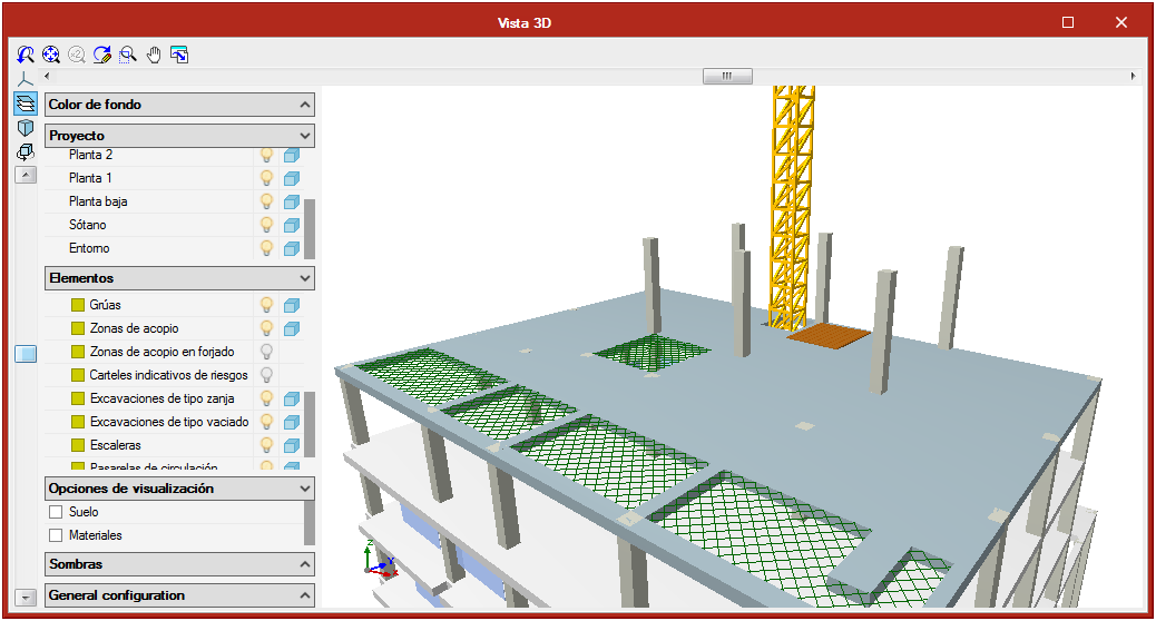
To begin working with Open BIM Switchboard, users must be connected to a previously created BIM model. The program imports the geometry of the building from the BIM model, if it exists in the model, and that has been generated and included in the model by CAD/BIM programs such as IFC Builder, Allplan, Archicad or Revit using IFC files.

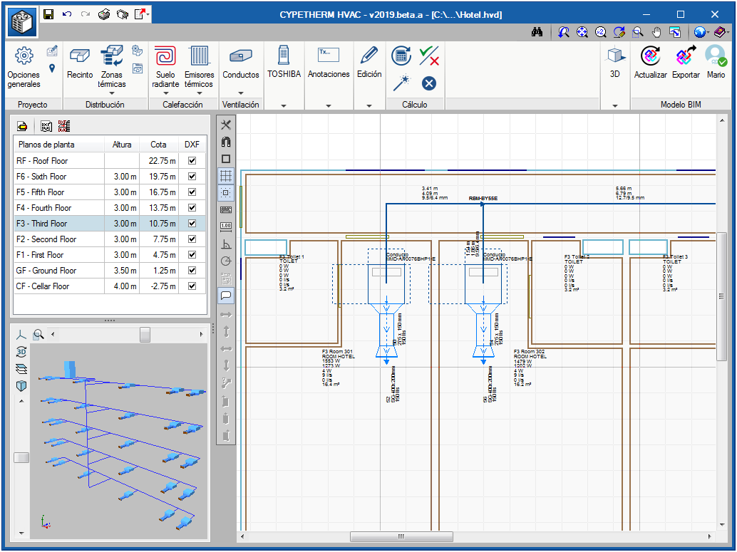
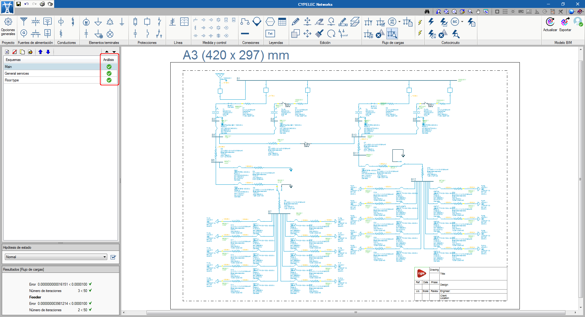
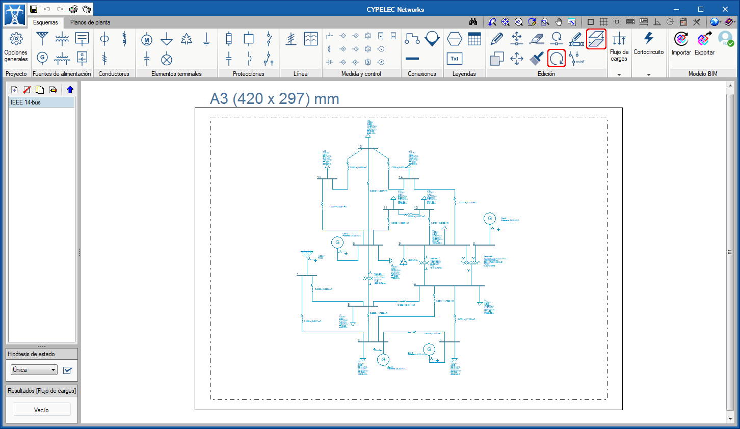
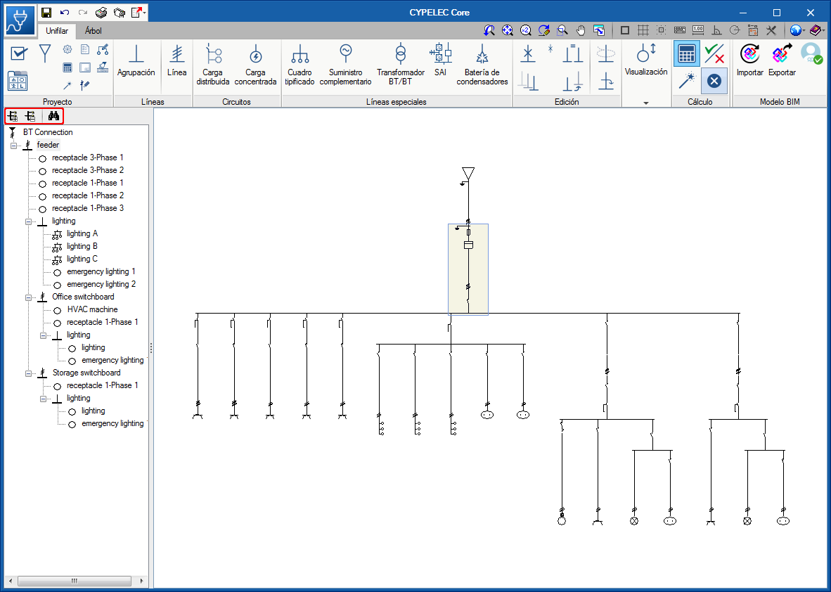
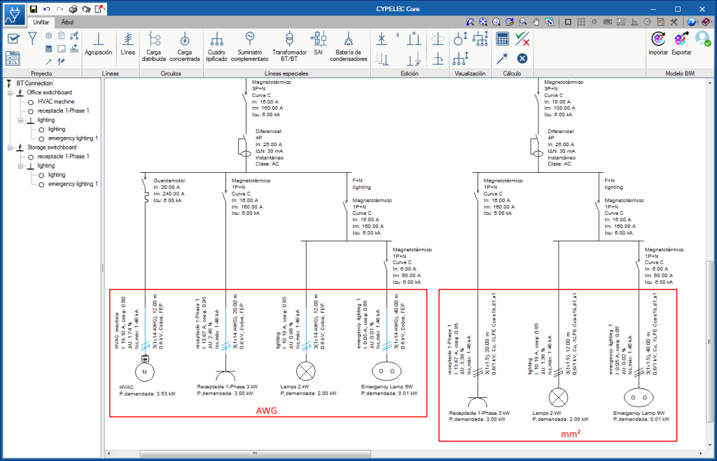
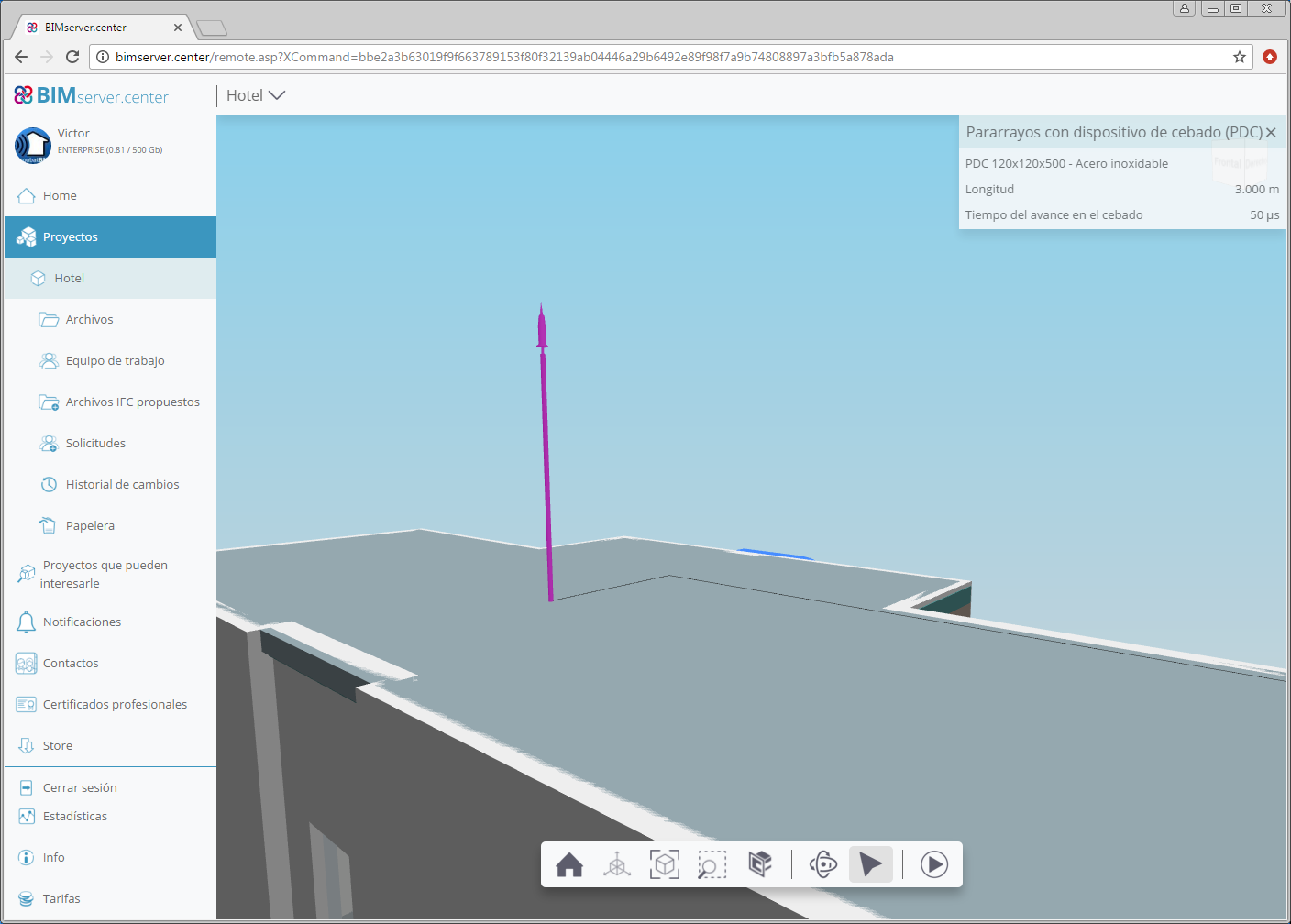
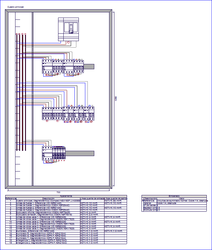
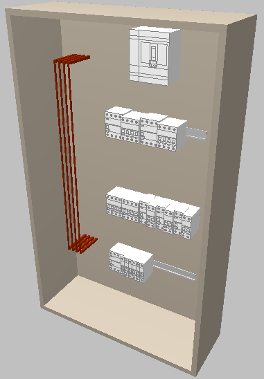
Additionally, if programs such as CYPELEC Core, CYPELEC NF and CYPELEC REBT have included IFC files of the single-line diagram of the installation in the BIM model, Open BIM Switchboard will import the panels and subpanels of the installation, together with their switchgear (including any busbars and bridge lines that have been defined). If, additionally, in the indicated CYPELC programs, the enclosures of the installation have been placed in the "Floor plans" tab, their position will also be imported. In this case, the designer must only define the box or cabinet that will contain the switchgear of each enclosure and position the switchgear, which has already been calculated by CYPELEC Core, CYPELEC NF or CYPELEC REBT, inside it.

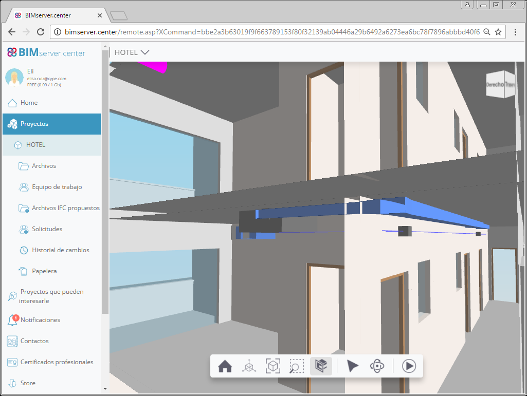
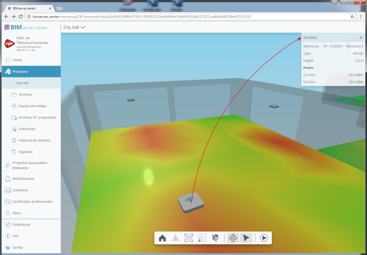
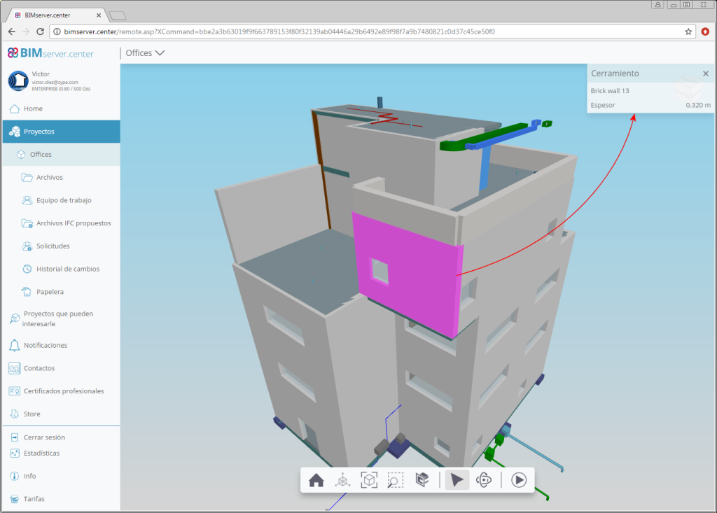
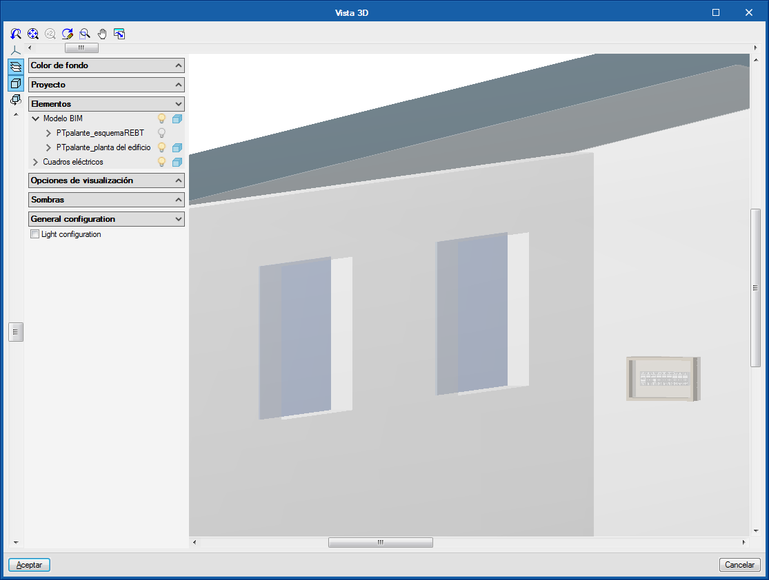
The position of the envelopes that is imported from CYPELEC programs is represented in the 3D view by a generic three-dimensional element. When users define the real dimensions of the envelopes in CYPELEC, they will not coincide with the generic element. The two elements that are displayed in the 3D view and can be activated or deactivated from the view separately. In Open BIM Switchboard, the position of the envelopes that have been imported from the BIM model can also be modified.

The Open BIM connection of "Open BIM Switchboard" with CYPELEC programs allows the project designer to greatly speed up the design process of the electrical panels. Nonetheless, Open BIM Switchboard allows users to design the envelopes from scratch. That is, there is no need for the geometric information of the building or the information of the switchgear that has been calculated in CYPELEC programs, to exist in the BIM model.

The operation of "Open BIM Switchboard" is the same as that of the "Cuadros" tab of CYPELEC REBT and "Tableaux" of CYPELEC NF.

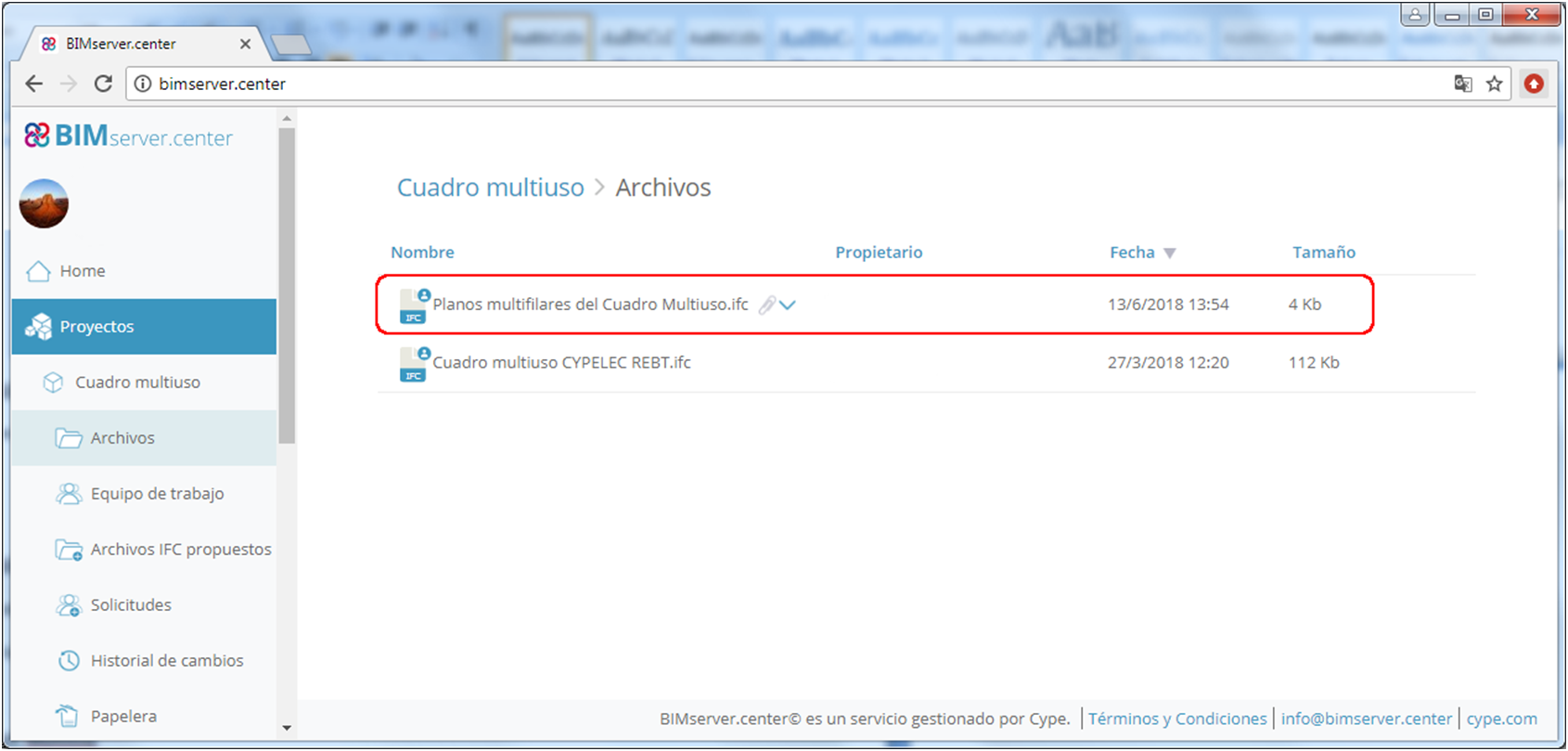
Open BIM Switchboard can be downloaded from the BIMserver.center platform.

To be able to work with “Open BIM Switchboard”, users must have the corresponding license permit, which is the same as that required in previous versions to access the “Design of electrical panels” module of CYPELEC REBT and CYPELEC NF.

More information on this new CYPE Open BIM program will be available shortly.

CYPE Lightning (new program)

CYPE Lightning is a free application designed to carry out the 3D layout of the elements of a lightning safety installation in any type of building, complying with the requirements imposed by users.

The program calculates, verifies and describes the safety installation including all the elements it consists of: ESE type lightning rod (early streamer emission lightning conductor), boxes with their respective grounding connections, connections with metal elements on façades and with receiver sets (antennas), grounding conductors, etc. The program, additionally, generate documents and relevant drawings to justify the lightning protection installation.

"CYPE Lightning" is integrated in the Open BIM workflow using the IFC standard. The program imports the geometry of the building from the BIM model (generated by CAD/BIM programs such as IFC Builder, Allplan, Archicad or Revit) and, if the risk level of the project has been evaluated with the "Open BIM CTE SUA 8" application, the value of the distance to the centre of the fictitious sphere, D, which describes the protection volume of the ESE, can be obtained from the BIM project.

Furthermore, "CYPE Lightning" exports an IFC file to the BIM model, containing the document that justifies the standard (.pdf). It also generates two independent 3D files (.gltf) to be able to view the lightning protection installation, as well as the properties of each element, and the protection volume in the web viewer of the BIMserver.center platform.

CYPE Lightning can be downloaded from the BIMserver.center platform.

More information on this new CYPE Open BIM program will be available shortly.

CYPETHERM Schematics (new program)

CYPETHERM Schematics is a free program designed to draw the circuit diagrams of hydronic air conditioning systems. The components are represented using symbols in accordance with ASHRAE standards.

In previous versions, CYPETHERM HVAC was the program that provided the tools to draw these diagrams in the “Circuit diagrams” tab. As of the 2019.a version, these tools have been removed from CYPETHERM HVAC to be implemented in the new "CYPETHERM Schematics" application. The design process of pipes that was carried out in the "Circuit diagrams" tab is still done in CYPETHERM HVAC.

CYPETHERM Schematics is not just a tool for drawing circuit diagrams. It has important advantages compared to conventional drawing programs and these are:

  • Iconography
    The iconography of the valves corresponds to ASHRAE standards, which avoids users from having to create their own drawings with the associated risk of using local representations that are not regulated.
  • Quantities
    All the elements are entities with associated properties, and appear in the quantities.
  • Equipment calculations
    Some elements have an internal calculation in the properties panel to help users design the equipment, for example, the expansion vessel, the air conditioners (or air treatment units) and generic fan-coils, and pipes. These calculations have an associated justification report, where the calculation is explained as well as the associated standard.

CYPETHERM Schematics is integrated in the Open BIM workflow using the IFC standard. It exports the documents containing information on the circuit diagrams of the included equipment to the BIM model.

CYPETHERM Schematics can be downloaded from the BIMserver.center platform.

IFC Builder

Architectural element information in the 3D viewer of BIMserver.center

As of the 2019.a version IFC Builder includes data on the geometric model in the file in "gltf" format, which is used to display the 3D model in the web viewer of the BIMserver.center platform. Thanks to this new feature, BIM project collaborators will be able to obtain the following information regarding the construction elements of the project:

  • Façades, party walls, partitions, basement walls, screeds, floor slabs and roofs.
    • Reference of the type
    • Thickness
  • Doors, external carpentry and glazed openings
    • Reference of the type
    • Width
    • Height
  • Skylights
    • Reference of the type
  • Nearby buildings and other obstacles
    • Height

Multi-instance

The possibility of opening IFC Builder several times simultaneously has been implemented, so users may work on several projects at the same time. This option was already available for other CYPE applications.

CYPECAD / CYPE 3D

Steel library for user-defined sections

In the 2019.a version of CYPECAD and CYPE 3D, users can now define steels for which they can indicate their elastic limit. The modulus of elasticity, thermal expansion coefficient, density and Poisson's ratio are defined internally by the program using the values of the steel. For U.L.S. checklists, the type of steel that is used can be seen.

As well as the elastic limit and depending on the selected code, additional data may be required to design connections.

The user steel library can be accessed from General Data. Rolled or cold-formed steel can be assigned to the sections as can steels that are established by each standard.

User-defined steels can be exported to the library to be used in other projects. They can also be selected as initial steels for the creation of new projects. The library is common to CYPECAD and CYPE 3D.

  • In CYPECAD:
  • In CYPE 3D

Effects of the vertical seismic component

As of the 2019.a version, CYPECAD and CYPE 3D can take into account the effects of the vertical seismic component by considering them as a percentage of the gravitational effect. Optionally, both programs apply a modification or adjustment coefficient that acts as the sum of the factor of the permanent loads in the seismic force combinations.

This coefficient increases the factor of the permanent loads in seismic combinations for unfavourable gravitational conditions and decreases the factor of the permanent loads for favourable gravitational conditions. In the first case, the gravitational effects are added to the seismic effects. In the latter, the gravitational effects counteract the seismic effects.

Consideration of the effects of the vertical seismic component

In building design, it is usual to calculate a structure to against the horizontal action of the earthquake and neglect the effects of the vertical component. However, in certain cases, it is advisable to consider these effects in the design.

CYPECAD and CYPE 3D apply an alternative procedure to the specification of spectra to consider the vertical seismic action, including its effects in seismic combinations by increasing the effect of the permanent load. This increase takes positive and negative values, due to the reversibility of the seismic action, and increases and decreases the gravitational effects in the combination. By doing so, the effects of vertical movement of the floor in buildings are simulated, such as:

  • The variance of the axial force in elements that resist vertical loads.
  • The variance in the localised deformation at the top of columns and the deflection at floor slab mid-spans.
  • The variance of the total vertical shear force that is transferred between floor slabs and columns.

CYPECAD and CYPE 3D propose a simple calculation for this modification coefficient, which provides a value that adapts to what is established in the standards and that is a function of the seismicity of the site that has been selected by the user. Some codes call it "vertical seismic pseudo-acceleration", but it does not represent the total vertical response, only the part that is combined with the horizontal response and the effects of gravity. The data proposed by the program can be modified by users, since different situations to those usually contemplated by the standards may arise.

In the section of the seismic data dialogue where users can activate whether or not the effects of the vertical seismic component are to be considered, there is a help button where more information on the calculation of the "vertical seismic pseudo-acceleration" coefficient can be found.

CYPECAD

Block foundation elements

As of the 2019.a version, it is possible to block the dimensions and reinforcement of footings, pile caps, and strap and tie beams so that they do not undergo any changes during the foundation design process.

The “Block/Unblock” option has been implemented in the “Foundation” menu of the “Beam Definition” and “Results” tab. When selected, users can choose which elements are to be blocked or unblocked. The option to block or unblock is also available in the “Foundation elements” editing window (footings and pile caps) and “Strap and tie beams”.

Column and wall distortions report

As of the 2019.a version, the “Column distortions” report is called “Column and wall distortions”. This report, in previous versions, only included column distortions. As of this version, the distortions of walls connected to the rigid diaphragm of the floor also appear in the report.

Move columns connected to beams and introduce new columns

Since the 2018.h version, when a column that is connected to beams on a floor is moved, the beams do not move automatically with the column. Neither are the beams reorganized when a new column is introduced and cuts existing beams. Due to this, the intersections between columns and beams must be recreated when columns are added or moved.

As of version 2019.a the program asks a question, and users can choose to either automatically recreate the intersections or to take no automatic action (in which case, users will manually recreate the beam-column intersections afterwards). Depending on the complexity, it is possible that the program will not be able to automatically resolve certain intersections, and so the program will warn of invalid results.

Block plane stress wall reinforcement

As of the 2019.a version, users can use the option “Block reinforced concrete wall reinforcement” (“Results” > “Beams/Walls”) to also select and block the reinforcement of plane stress concrete walls.

Edit torsional stiffness reduction coefficients for steel and timber beams

Since previous versions, torsional stiffness reduction coefficients can be defined for concrete beams. As of the 2019.a version, it is also possible to reduce the torsional stiffness for steel beams and timber beams. These coefficients can be edited in the "Torsional stiffness reduction coefficients" dialogue (Project > General options > Torsional stiffness reduction coefficients).

Update line loads of construction elements and post-tensioned tendons

The option “Update line loads of construction elements and post-tensioned tendons” has been implemented in the “Loads” menu in the “Beam Definition” tab.

As of previous versions, the program calculates the line loads of construction elements ( “Beam Definition” tab > "Loads" menu > "Construction elements" option) and post-tensioned tendons ("Beam Definition" tab > "Post-tensioned" menu). If changes were made in these elements or in others related to them that could affect self-weight values, the program did not recalculate the loads until the project was analysed or until drawings or reports were obtained.

As of the 2019.a version, when users select the new option: “Update the loads of construction elements and tendons”, recalculates the aforementioned loads, which allows users to view their values on-screen after the modifications have been made, without the need of having to analyse the project or print drawings or reports.

Ungrouped column schedule

As of the 2019.a version, the Column schedule can be displayed showing the column groups defined in “Results” or ungrouped, in which case each column will be displayed in a column of the schedule.

CYPELEC Core

Selection of AWG American calibre cables

The 2019.a version of CYPELEC Core allows users to select AWG (American Wire Gauge) cables.

These cables can be selected in the “Cables” dialogue box (“Configuration” button in the toolbar > “Element library” > “Cables”), where users can choose, as well as the calibres that were available in previous versions, calibres 18 AWG to 2000 AWG.

When the AWG cable selection is activated, their selection is enabled in the line editing panels.

The panel adapts to the selected type of cable (IEC or AWG), in terms of the parameters that define the cable, type of channel and installation method.

The checks are also adapted to the AWG cable selection. For example, the maximum allowable current check is substituted by the amapacity check of the cable according to the American standard (Natinal Electrical Code).

Since, as of this version, users can work on the electrical installation with cables in mm2 or AWG, in order to distinguish lines with IEC or AWG cables, they are drawn in different colours. These colours can be changed in the “Diagram presentation” section of the “Circuit diagram” dialogue box (“Circuit diagram” button of the “Project” section of the toolbar).

Section check of the neutral conductor by harmonic content

The 2019.a version of CYPELEC REBT, CYPELEC NF and CYPELEC Core include the check of the neutral section due to the possible contents of harmonics in three-phase circuits, in accordance with the international code: IEC 60364-5-52, section 524.2.1.

Use of the breaking capacity of previous protections

Section 434.5.1 of the UNE-HD 60634-4-43 code allows users to use a lower breaking capacity of the protection device of the loading zone if another protection device is installed before with the required breaking capacity. It is a solution for circuits that start at distribution panels that are close to transformers.

As of the 2019.a version, CYPELEC REBT, CYPELEC NF and CYPELEC Core contemplate the possibility of using the breaking capacity of previous protection devices in the design options. The breaking capacity can be that of the fuses or circuit breakers depending on the selection.

The check report includes a comment on the matter in case this option has been used.

Enlarged fuses library

Nominal current fuses: 224 A, 355 A and 450 A, have been added. This selection is deactivated by default. It can be activated in “Configuration” > “Elements library” > “Fuses”. This way, the new currents will be available when the fuses are edited.

Expand/contract and find lines in the tree diagram of the installation

In the “Single line” tab, a toolbar has been added in the part above the tree structure of the installation that allows users to expand and contract the diagram, and search lines of the single-line diagram. When a specific line is sought, the line that is found is indicated in the tree structure and highlighted in the diagram.

CYPELEC Multiline

Export multi-line diagram drawings to the BIM model

As of the 2019.a version, CYPELEC Multiline allows users to export an IFC file to the BIM model containing the multi-line diagrams of the electrical installation that have been generated or included by users. The IFC file with the drawings will be added to the project files in BIMserver.center.

CYPELEC Networks

Quick connection introduction

Since previous versions, the “Connections” tool had to be selected from the top menu of the program window to be able to connect elements that have been introduced in the installation (transformer, supply connection, cable, transmission line, impedance, load...).

As of the 2019.a version, the connection procedure of the elements that are introduced in the installation has been improved. Now, if the right mouse is pressed after entering an element, the "Connections" tool is activated automatically without the need to move the mouse to select this tool in the top menu.

New editing tools (Rotate group and copy to another diagram)

In the “Edit” block of the CYPELEC Networks toolbar, two new options have been added: “Rotate group” and “Copy to another diagram”:

  • Rotate group
    Allows for several elements to be captured at once and then rotated.
  • Copy to another diagram
    Allows for one or several elements of a diagram to be selected then copied to another diagram. This tool works in a similar way to copying between floors of other CYPE programs.

Status column in the diagrams list

When the load flow or short circuit analysis is launched, all the diagrams of the project are designed, not only the one that is active.

To represent the final design status, a column is added to the right of the diagrams, so users can quickly view the result.

CYPETEL Wireless

3D view of emitter radiation diagrams

The possibility to obtain a 3D view of the radiation diagrams of the emitters. Furthermore, for each receiver, it is possible to see where the radiation diagram of each associated emitter is directed towards.

Emitter information in the 3D viewer of BIMserver.center

As of the 2019.a version, CYPETEL Wireless exports data from the wireless network to the file with “.GLTF” extension, used to show the 3D model in the integrated viewer in BIMserver.center and in its application for mobile phones. Thanks to this new feature, the collaborators of the BIM project can obtain the following information on the emitters that have been selected for the project:

  • Reference of the emitter
  • Type of emitter
  • Installation height
  • Transmission power

CYPELUX / CYPELUX EN / CYPELUX LEED

Reading of the suspended ceilings defined in the BIM model

Open BIM Suspended Ceilings (new program that has been implemented in this version) exports the layout of the suspended ceilings of the project to the BIM model. Also in this version, all CYPELUX programs (CYPELUX, CYPELUX EN, CYPELUX CTE, CYPELUX RECS, CYPELUX HQE and CYPELUX LEED) can read the suspended ceiling panels and show them as a template on the floor plans of the project. This way, it is easy to verify where exactly, a light can be placed so not to collide with the hanging elements of the suspended ceiling of the accessible panels.

The visibility of the suspended ceiling can be controlled using the “Layer management” option, which is located in the “View” menu of the application toolbar.

CYPESOUND / AcoubatBIM by CYPE

Export project documents to the BIM model

The option to “Export” to IFC has been implemented in the “BIM model” group of the toolbar in all CYPESOUND programs (CYPESOUND, CYPESOUND CTE, CYPESOUND RRAE and CYPESOUND DRAPDE) and in AcoubatBIM by CYPE. This option allows users to integrate the justification reports of the project in the BIM project, in .pdf format. These reports can be viewed directly using the BIMserver.center platform and its mobile applications for Android and iOS.

Reading of electrogen groups of the “Open BIM Inmesol” application as sound sources

As of the 2019.a version, all CYPESOUND programs (CYPESOUND, CYPESOUND CTE, CYPESOUND NRA, CYPESOUND RRAE and CYPESOUND DRAPDE) and AcoubatBIM by CYPE are able to read electrogen groups from the BIM model and add them to the program as noise sources. During the import process, the application automatically calculates the values of parameters "r" (distance between the source and the closest enclosure of each affected area) and "D" (directivity factor of the machine) corresponding to each set, based on the position of the source and the geometry of the building.

These devices can be introduced in the BIM model using the new application: “Open BIM Inmesol”, which is available on the BIMserver.center platform.

AcoubatBIM by CYPE

Aerators in the windows and skylights library

As of the 2019.a version, AcoubatBIM by CYPE allows users to introduce aerators directly in the types of windows and skylights defined in the library of the application. This way users do not have to include each aerator independently in the model when it is installed together with the glazed opening.

Equipment noise analysis along corridors

As of the 2019.a version, AcoubatBIM by CYPE takes into account the indirect airborne transmissions along corridors to evaluate the sound pressure level produced by the equipment of the building. Thanks to this improvement, it is now possible to analyse equipment noise between non-adjacent spaces.

Export documents to the BIM model

The option to “Export to IFC” has been implemented in the “BIM model” group of the toolbar. This option integrates the reports in the BIM model. These report, in .pdf format, are those corresponding to the “Results report”, “Material properties” and “Materials schedule”. These documents can be viewed directly using the BIMserver.center platform and its mobile applications (Android and iOS).

CYPEFIRE Design

Requirement of a fire alarm control panel

The 2019.a version includes the requirement for detection centers over the zones. It works like other requirements that have been implemented in the program: by introducing the article and the code description of the requirement, as well as being able to edit the limits from which this equipment begins to be necessary.

With this new requirement, detectors, alarm systems and alarm buttons can be introduced independently without having introduced a detection center.

Maximum elevation below ground level that is accessible by the public

As of the 2019.a version, CYPEFIRE Design performs a new check on the zones. It is the "Maximum elevation below ground level that is accessible by the public".

With this check, it is possible to edit the maximum rising height that can be covered by any occupant below ground level. Like the rest of the checks, it is possible to edit the article and the code description.

This check limits the maximum level below ground that can be accessed by the public. This does not imply that there cannot be spaces or floors below this limit, although in that case their occupation must be null.

Maximum admissible occupancy

In many projects, the requirements and checks set by the regulations have an occupancy limit restriction.

As of the 2019.a version, CYPEFIRE Design allows users to indicate the maximum allowable occupancy in the "Building configuration” dialogue box (General options > General settings section > "Building configuration" button). The program calculates the total occupancy and compares it to the value that has been entered in this new option.

The calculation is carried out by obtaining all the occupancies of the spaces involved in the fire protection design of the BIM model.

In the "Building configuration" dialogue box, as well as entering the value of the "Maximum admissible occupancy" it is possible to indicate the article of the standard and the description.

Stair communication below/above ground level

The 2019.a version includes a new check for stairs: “Allow for direct communication between floors above and below ground level” (General options > Checks > Stairs button > edit or create a check).

If this option is activated, the program allows for an ascending stair to share the landing with a descending stair, to create a single staircase.

If the option is deactivated, the ascending stair and descending stair cannot share the landing and must be separate, in two different staircases, and by doing so, prevents any smoke coming up from floors lower down from invading the higher floors of the project.

The image shows two different staircases. As occurs with other checks, it is possible to add the article and description of the code that allows for there to be direct communication between them.

Design

The option: “Design of the evacuation routes” has been implemented in the “Results” menu.

In previous versions of CYPEFIRE Design, users had to, once the project was analysed, check and modify any evacuation routes that failed one by one, and if the project had to be reanalysed, this process had to be repeated in an iterative manner.

With the “Design of the evacuation routes” option, the program automatically modifies the width of all the evacuation routes to the minimum allowable width depending on their occupancy. Users can block the widths of the evacuation routes they select, so they cannot be modified by the design process.

3D view

The 2019.a version of CYPEFIRE Design includes the “3D view” button in the main program menu. This tool shows the 3D view of the BIM project in a new window. This 3D view is the same view that appears in the bottom left zone of the screen, but the configuration of the visible elements and their perspective are independent in each view.

Equipment information in the 3D viewer of BIMservercenter.com

As of the 2019.a version, CYPEFIRE Design exports data on the equipment used in the fire protection installation it designs to the BIM model. This data is included in the “.GLTF” format file that is used to show the 3D model in the integrated viewer of the BIMserver.center web platform and in the mobile device application – App.

Thanks to this new feature, the collaborators of the BIM project can obtain the following information regarding the elements of the project:

  • Fire extinguishers
    Reference, description, height, type and efficiency.
  • Fire hose reel
    Reference, description and diameter.
  • Hydrants
    Reference, description and diameter of the connections.
  • Standpipes
    Reference, description, type and diameter of the standpipe.
  • Fire alarm buttons
    Reference, description and height.
  • Alarm systems
    Reference, description and type.
  • Detection systems
    Reference and description.

Type of ERT projects (Lieux du travail) for the Moroccan code

In the 2019.a version, the ERT (Lieux du travail) type of project has been included for the Moroccan code “Règlement de sécurité contre les risques d’incendie et de panique dans les constructions”. With this implementation, all the types of projects included in the aforementioned code are included in the program.

The ERT type of project is selected from the import assistant of the Moroccan code that is indicated in the general options panel, which also includes the “Bâtiment d’habitation”, “Établissement recevant du public” and “Immeubles de grande hauteur” type of projects that were implemented in previous versions.

This type of project refers to all buildings that are destined to hold working posts except buildings that can be defined as “Immeubles de grande hauteur” or “Établissement recevant du public”.

CYPEFIRE Sprinklers

Contour map diagrams with pipe data

As of the new 2019.a version, CYPEFIRE Sprinklers includes a graphical representation of the data calculated using contour map diagrams on the pipes of the installation.

The representation of the results using contour maps is activated and configured in the program using two options that are included in the “Analysis” menu:

  • Graphical analysis of the results
    This option activates the graphical representation using contour map values on the sprinkler system, which allows for the following results, which are obtained from the application, to be seen:
    • Flow
    • Velocity
    • Pressure loss
    • Length
    • Height
  • Range of results for the graphical analysis
    This option allows users to define specific analysis intervals, so the program will only graphically represent the data that lies within each range.

This tool allows users to carry out a quick analysis of the sprinkler installation. For example, it is possible to instantly view where large pressure losses are being produced to design the network.

Contour map diagrams of pipes in the 3D viewer of BIMserver.center

When the export is carried out from CYPEFIRE Sprinklers to the BIM project, the generated IFC file can optionally include several "gltf" files that contain the contour map diagrams of each result (flow rate, velocity, pressure losses...) in the three-dimensional view.

This allows users to visualise the contour maps in the 3D viewer of BIMserver.center, in the same way as was already done in other Open BIM applications such as CYPETEL Wireless or CYPELUX. These "gltf" files are independent of what was already generated for the sprinklers installation, so each of them can be viewed independently in the 3D viewer of BIMserver.center.

Equipment information in the 3D viewer of BIMserver.center

As of the 2019.a version, CYPEFIRE Sprinklers exports, to the BIM model, data on the elements used in the fire safety installation from the sprinklers that it designs. This data is included in a “.GLTF” format file that is used to show the model 3D both in the viewer that is integrated in the BIMserver.center web platform and in its application for mobile devices -App.

Thanks to this new feature, BIM project collaborators can obtain the following information regarding the elements that have been introduced in the project:

  • Sprinklers
    Reference, height, type, orientation and K-factor.
  • Pipes
    Reference, material, diameter and roughness.
  • Supports
    Reference, diameter and height.
  • Seismic supports
    Reference, angle at which it is placed and supported load.
  • Tanks
    Reference and volume.

3D view

The 2019.a version of CYPEFIRE Sprinklers includes the "3D View" button in the main menu of the program. This tool shows the 3D view of the BIM project in a new window. This 3D view is the same view that appears in the lower left-hand area of the screen, but the configuration of the visible elements and their perspective are independent in both views.

Reading of suspended ceilings defined in the BIM model

Open BIM Suspended ceilings (new program implemented in this version) exports the layout of the suspended ceilings of the project to the BIM model. Also in this version, CYPEFIRE Sprinklers can read the panels of the suspended ceilings from the BIM model and show them as a template in the floor plans of the project.

Thanks to this, users can view the position of the suspended ceilings on the floor plan and introduce the sprinkler system installation avoiding any collisions with the support elements of the suspended ceilings of the accessible panels.

Their visibility can be deactivated in “Layer management”, so not to hinder users in more advanced design phases.

CYPETHERM EPlus

Daikin heat pumps for hot water

In the “Hot water systems” section, the “Heat pump for hot water” option has been implemented, where users can choose amongst the different models that the manufacturer Daikin has to offer for this type of equipment.

Ventilation using the air conditioning system

Changes required to implement ventilation using the air conditioning systems

The 2019.a version of CYPETHERM RECS Plus and CYPETHERM EPlus allows users to simulate the entrance of outdoor air to ventilate the building via the air conditioning system. In previous versions, the program considered that the air that was required to ventilate the building entered directly via the spaces.

Within each Zone, in the “Ventilation and infiltrations” section, the new variable: “Type of ventilation” appears, where users can choose amongst:

  • Natural
    Is the possibility that existed in program versions up to the 2019.a version to contemplate ventilation.
  • Mechanical
    This type of ventilation was already available in CYPETHERM RECS Plus and as of the 2019.a version, is also available for “CYPETHERM EPlus”. The mechanical ventilation can consider the consumption of the fans associated with this function.
  • Via the air conditioning system
    This type of ventilation is the type that must be chosen to simulate air entering via the air conditioning system associated with the zone.

The “Heat recovery” option has disappeared from the “Ventilation and Infiltrations of the Zone” panel. As of the 2019.a version, heat recovery is defined for the air conditioning systems that can carry out this function, which implies a significant improvement in the design model.

Furthermore, to carry out the ventilation via an air conditioning system, equipment that can carry out this function must be defined in the zone. With this purpose in mind, new options have been habilitated, in the 2019.a version, in “constant performance equipment” and “air-air conditioning systems of the “Rooftop” and “Single-zone AHU””. Heat recovery units have also been included as new equipment.

Heat recovery in constant performance equipment

In “Constant performance equipment”-type terminal units, the “Heat recovery” option has been included, which allows users to simulate the exchange of sensible and latent energy between the renewal and extraction air flow. To do so, users must define the efficiency of this exchange. During the simulation, the constant performance equipment will only recover heat when the indoor air conditions are more favourable than those of the outside air.

Outdoor air inlet in air-air conditioning systems such as Rooftop and Single-zone AHU

Within "Air conditioning systems of constant volume", the "Rooftop" and "AHU" type of single-zone systems have the new option "With outdoor air intake". If users enable this option, the ventilation air of the zones to which this system is connected will enter through it. Additionally, the heat recovery and free cooling functions can be defined for this equipment.

New air conditioning systems: single-zone and multi-zone heat recovery units

As of the 2019.a version, it is possible to simulate sensible and latent heat recovery units, with an external air bypass function. Two versions of this type of equipment have been added: as a terminal unit (single-zone) and as a centralized system (multi-zone).

Within "Terminal Units", users can select the type of "Heat recovery unit". This equipment will be assigned to the zone in which it is defined.

The new category: "Centralized ventilation system" has been added in "Air-air conditioning systems", where users can select the heat recovery equipment. Like the rest of air conditioning systems, this equipment is connected to the zones via the corresponding terminal units. Within air-air conditioning terminal units, the Heat Recovery unit is compatible with the Air discharge terminal.

Time with unsatisfied heating and cooling demand

As a result of the energy simulation of the building, the number of hours during the month in which the air conditioning systems have not been capable of overcoming the heating and cooling loads are displayed. This results substitutes the “Useful energy provided for heating and cooling” that was shown previously.

CYPETHERM HVAC

Separation of the “Circuit diagram” tab

In previous versions, the workspace of CYPETHERM HVAC consisted of two tabs:

  • Circuit diagrams
    Where were the necessary elements to draw the diagram of the equipment that make up the air conditioning installation and where the pipes of the available air conditioning systems and the calculation of the air flow were designed.
  • Floor plans
    Where the rest of the calculations of the air conditioning installation were carried out after placing all the elements it was composed of on the geometry of the building.

As of the 2019.a version, the "Circuit diagrams" tab disappears from CYPETHERM HVAC and becomes part of the free application "CYPETHERM Schematics", which is a drawing tool for drawing the circuit diagram of the installation. The pipe design process that was carried out in the "Circuit diagrams" tab is still done in CYPETHERM HVAC where now, the 3D geometry of the building (that comes from the BIM model) and its plan views are represented (view corresponding to the "Floor plans" tab of the previous versions).

Analysis of systems on the BIM model

As of the 2019.a version, the analysis of all the systems that make up the air conditioning system is carried out entirely in CYPETHERM HVAC. Users must:

  • Locate the indoor units
  • Connect them by pipes to the outdoor unit
  • Select "Analysis"

With the design process, CYPETHERM HVAC automatically performs the following tasks:

  • Checks for design limitations
  • Corrects power according to temperatures
  • Checks models with thermal loads
  • Selects the model for the outdoor unit
  • Calculates the diameter of the pipes
  • Generates a results report and the quantities of the installation.

Height above the floor of equipment, ducts and pipes

In previous versions, the elevation of the air conditioning installation equipment (VRF, Aerothermal, Multi-splits and Splits), ducts and pipes was defined. As of the 2019.a version, to indicate to the program the elevation above ground level of these elements, the "height above the ground" where they are located is indicated. This parameter appears in all the introduction dialogs of the mentioned equipment, ducts and pipes. This allows, for example, for several networks to be drawn on the same floor without colliding (for example: discharge and return ducts, and pipes).

Vertical pipe and conduit spans

In order to introduce vertical spans of ducts and pipes, users must define:

  • Height above the initial floor
  • The initial floor (by selecting it from a drop-down button)
  • Height over the final floor
  • The final floor (by also selecting it from a drop-down button)

Export documents to the BIM model

The documents generated by the program (calculations, plans, measurements) are automatically attached in PDF format each time the user exports the BIM model of the project to the BIMserver.center platform.

New grilles library

The 2019.a version of CYPETHERM HVAC includes three grilles libraries (discharge, return and extraction) that cover a range of flow rates from 25 to 1806 l/s. Each one can be imported once in the project that is being worked on. Additionally, all the elements that have not been used can be deleted from the project.

Equipment positioning improvements

As of the 2019.a version, when an equipment unit is placed on the floor plan, a green line is included that emerges from it. When the unit is selected with the mouse cursor, a graduated circle appears that allows users to rotate the unit about itself. This rotation maintains a certain resistance at right-angles and at 45º.

As well as the graduated circle, when an equipment unit is introduced, a small menu appears with orange arrows (located between the plan view and the list of floor plans of the building) that allows for the unit to be introduced with a specific angle (the four right-angle positions or any selected angle) without the need to have to select the green line.

Arquimedes

Presentation dialogue or start

As of the 2019.a version, when Arquimedes is launched, a presentation window is displayed where users can select the bill of quantities, price bank, work area or example that is to be opened. This way, databases (bill of quantities or price banks) are more easily opened, or work areas more easily loaded.

The presentation window appears if no databases were open when Arquimedes was closed in the previous session.

This window shows the sections, which display the information of the bills of quantities, price banks, work areas or examples that are available.

Several databases can be selected at the same time from the same section. To open the selected databases or work areas, simply click the “Enter” key of the keyboard.

Window viewing system

In the 2019.a version of Arquimedes, users can choose between two window view systems (Classic system and System based on tabs). Either system can be activated using the “Windows systems” option of the “Window” menu:

  • Classic system
    This is the window viewing system that was available as of previous versions. Users can organise the views and windows of the open databases in “Cascade”, “Horizontal mosaic” and “Vertical mosaic”.

  • System based on tabs
    If this option is activated, a window with several tabs, which correspond to the views of the databases that are open, is displayed.

    Different groups of windows can be organised (“Vertical groups”, “Horizontal groups” or “Floating widows) with one or several tabs. This organisation can be done from:


    • The “Window” menu

    • The contextual menu of each tab
      This menu drops down by pressing the arrow that appears when the mouse cursor is placed on a tab.

    • Manually
      By dragging each tab to the desired position. Whilst the tab is being dragged, it is translucent and displays a blurred diagram so users can place the new tab in a new window, next to the one from which it came from (above, below to the left or to the right).

The view system based on tabs is helpful for users to organise the views and windows of the open databases. Furthermore, the floating windows of the view system can be moved freely, even to other monitors user may have for the same machine.

More options in the Job Control toolbar

To help with the introduction and visualisation of job control data, the following buttons have been provided in the Job control toolbar:

  •  Purchase groups
    Allows users to create or access supplier groups. Using this tool, users can more easily offer requests, price offers, and hence, elect contracts to be carried out.
  • Job supplies
    Displays a list with all the unit items that have been used in the projects and allows users to organise them into purchase groups to be able to generate purchase comparatives and contracts more easily.
  • Contract supplies
    Allows users to select the job supplies that are to be contracted and to prepare the required comparatives to decide which supplier the purchase is to be assigned.
  • Purchase comparatives
    Shows all the price comparatives that have been defined in the project and allows users to generate the contracts of the supplies that have yet to be contracted.
  • Generate contracts
    Allows the program to run through all the purchase comparatives to locate all the supplies that have yet to be contracted and have an assigned supplier, to propose which contracts have to be generated.
  • Job contracts
    Displays a list containing all the existing contracts of the current project.