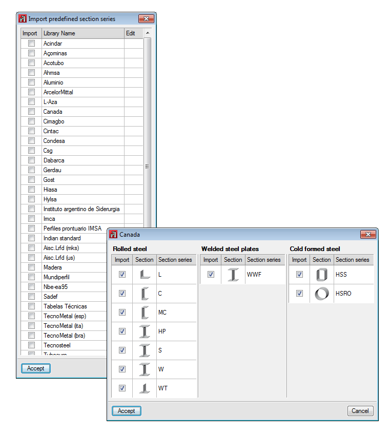
Section library management
The “Management of the section library” option (Job menu) allows users to import predefined section series into the current job, establish the default lists available for new jobs and export section series of the current job to different file formats. All this is possible using three options that appear in a dialogue box when the “Management of the section library” option is executed.
Assign sections to bars
As well as the new section library management, the process undertaken to assign sections to the bars to be introduced and those already introduced has been improved:
- New (Bar menu)
As of the 2015.a version, the “New” option in the “Bar” menu opens a dialogue box where users can:
- Select the section of the bar that is going to be introduced. This can be done in two ways:
- By selecting it from the libraries available in the job (the same way as with the “Describe section” option).
- By selecting it from a list where the sections used in the job are displayed.
- Establish the layout of the section (adjustment point and rotation angle)
- Select the section of the bar that is going to be introduced. This can be done in two ways:
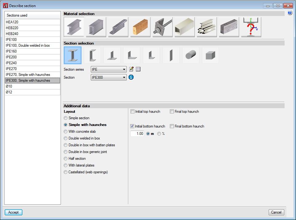
- Describe section (Bar menu)
A list of the sections that are being used in the job has been added to the dialogue box that opens upon selecting this option and then selecting a bar, from which users can select a section. Additionally, other options which already existed since previous versions (material selection, type of section, section series, section layout – simple, with haunches, double welded in a box...-, edit section series, access to library management) are located in the same dialogue box (without having to open other dialogues like in previous versions). - Root radius and angle of the flanges of rolled sections
By editing rolled sections, users can define:
- For any rolled section:
- The root radius between the web and flange
- The root radius between the sides of the flanges
- For I-sections and simple channels
- Inclination of the flanges
- For any rolled section:
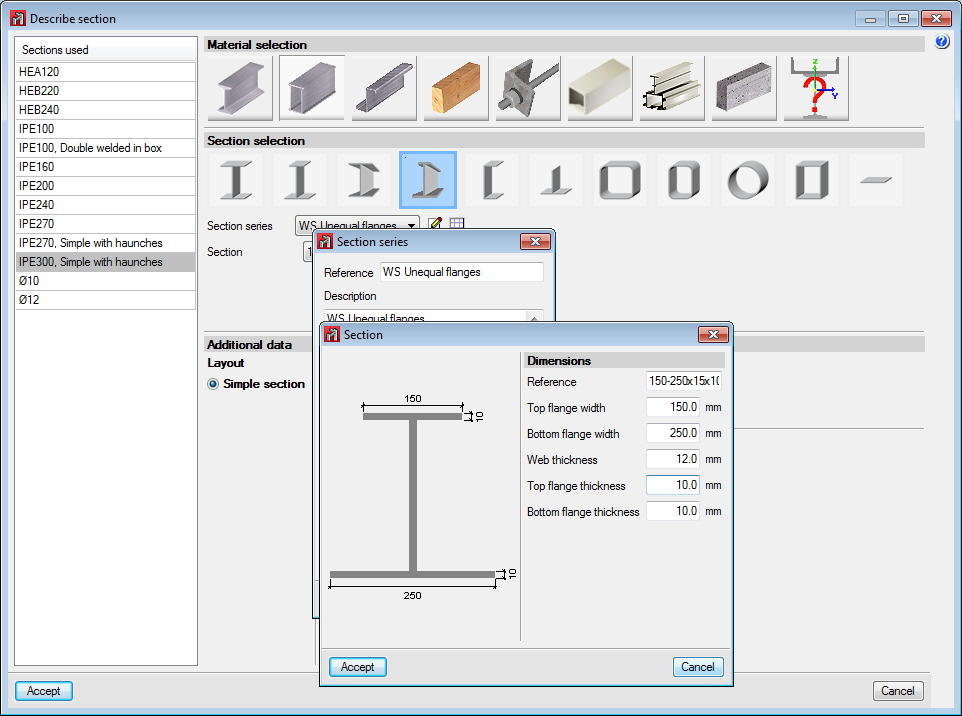
- New welded section type
I-sections with different flange lengths and variable depth have been added.
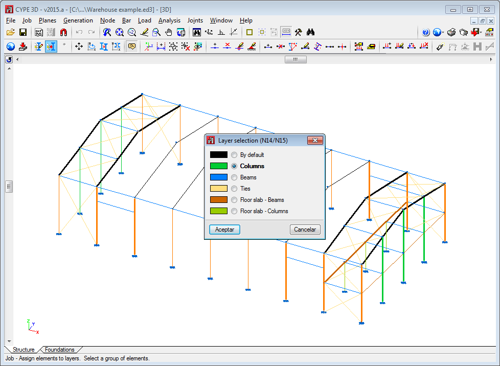
Layer management (bars and panels)
Three options have been created in the “Job” menu, which allow users to class bars and load panels in layers defined by themselves, so they may be viewed in their respective layers and for bars to only interact with the elements of the visible layers.
- Layer management
Allows users to define layers or group views for elements or panels. Users will only be able to interact with elements belonging to layers which are visible. Elements and panels alike will be assigned to the active layer when created. - Assign elements to layers
Users can change the layer of the selected elements. - Assign panels to layers
This allows users to change the layer assigned to the selected load panels.
Move, rotate, copy and copy with symmetry
The 2015.a version includes a wide range of options to define the geometry of the structure. These are located in the “Job” menu and are:
- Move elements
Moves a selection of elements to a new position.
Select the elements to be moved using the left mouse button. Once selected, press the right mouse button, then the left and mark the two points which define the displacement origin and its magnitude. - Rotate elements in the XY plane
Rotates a selection of elements about the global z axis. If the operation is carried out in a 2D view, the rotation will be performed in the plane of the view.
Select the elements to rotate using the left mouse button. Once selected, press the right mouse button, then the left, and mark the two points which define the rotation angle. - Rotate elements about an axis defined by two points
Rotates a selection of elements about an axis defined by two points. If the operation is carried out in a 2D view, the rotation will be performed in the plane of the view. Select the elements to rotate using the left mouse button. Once selected, press the right mouse button, then the left. Mark the two points which define the rotation axis followed by the rotation angle about the axis. - Rotate elements in the XY plane given three points
Rotates a selection of elements about the global z axis with respect to the origin indicated by users and with the angle defined by any three points. If the operation is carried out in a 2D view, the rotation will be performed in the plane of the view. Select the elements to rotate using the left mouse button. Once selected, press the right mouse button, then the left. Mark the point of origin of the rotation and the three points which define its magnitude. - Copy elements
Copies a selection of elements at a new position.
Select the elements to be copied using the left mouse button. Once selected, press the right mouse button, then the left and mark the two points which define the displacement origin and its magnitude. - Element symmetry in the XY plane
Carries out a symmetrical copy of a selection of elements with respect to the plane defined by a vector introduced by users and the global z axis. If the operation is carried out in a 2D view, the symmetry will be carried out with respect to the line defined by the vector.
Select the elements to be copied using the left mouse button. Once selected, press the right mouse button, then the left and mark the two points which define the origin of symmetry and the direction of the vector in the global XY plane. - Element symmetry with respect to a plane
Carries out a symmetrical copy of a selection of elements with respect to a plane defined by three points. If the operation is carried out in a 2D view, the symmetry will be carried out with respect to the line defined by the first two points. Select the elements to be copied using the left mouse button. Once selected, press the right mouse button, then the left and mark the three points defining the plane of symmetry.
Import text files
Generates the geometry of the job automatically using a text file with a specific format. The format these text files are to have is specified in the dialogue box that appears when this option is selected from the “Job” menu to select the file to be imported.
Import DXF and DWG files
The option to import files in DXF and DWG format to automatically generate the geometry of the structure (Job > Import DXF and DWG files) incorporates the following improvements:
- Layer generation
As of previous versions, when CYPE 3D imports a DXF or DWG file, users select the layers of the DXF or DWG which contain the elements to be imported. As of the 2015.a version, the layers selected in the DXF or DWG file are created in CYPE 3D with the same name and colour as they had in the file. Imported bars remain assigned to the same layer as they were in the DXF or DWG file. This is possible because the creation of view layers has been implemented in CYPE 3D. - Insertion point selection
CYPE 3D requests users to define an insertion point to insert the geometry of the structure obtained from a DXF or DWG file. The program allows users to:
- Import at the position defined in the DXF or DWG file
- Select the reference point for the import
Move bar end
The option “Move end” has been implemented in the “Bar” menu, and allows users to move the end o the selected bar without having to move any other bars connected to the node reaching that end. To move all the bars connected to a node, the “Move” option in the “Node” menu can be used (option available since the first version of Metal 3D).
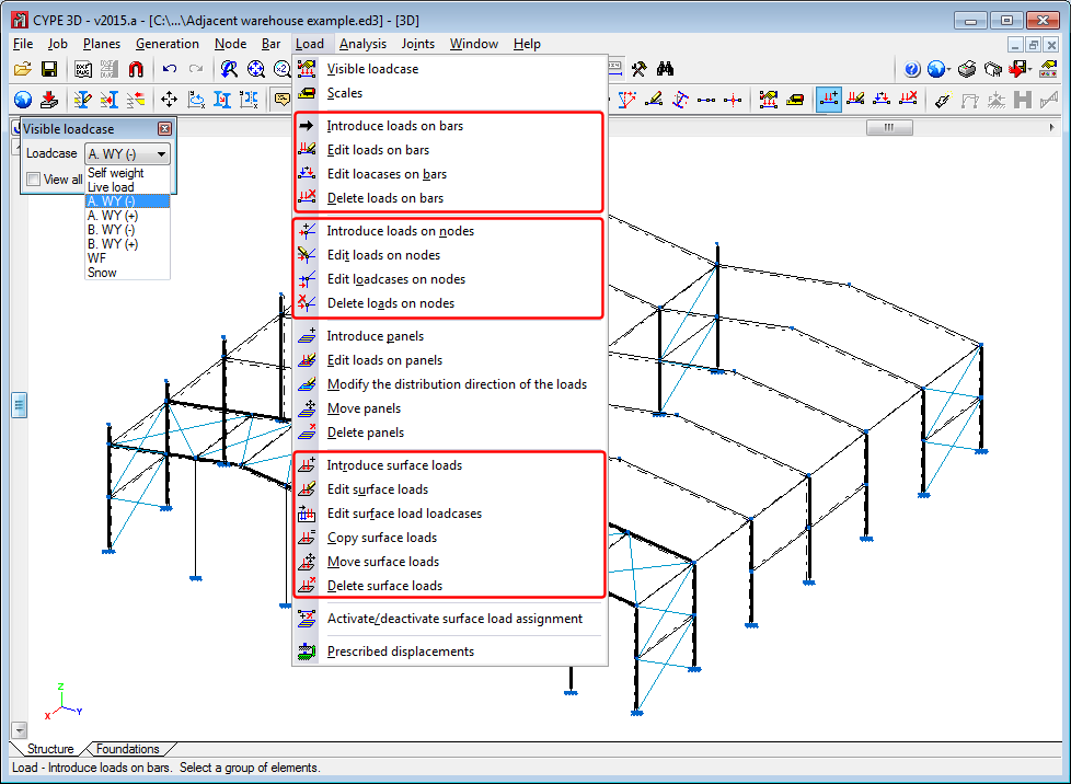
Select and edit loadcases (on bars, on nodes and surface loads)
To help users when editing loads, a dialogue box appears on screen (visible loadcase) when any of the load editing options are selected from the “Load” menu (see image).
The visible loadcase at any moment can be selected in this dialogue box.
Three new options have been implemented to modify the loadcase assigned to each load: “Edit loadcases on bars”, “Edit loadcases on nodes” and “Edit surface load loadcases”. These allow for the loadcases of several loads to be edited at the same time.
Move surface loads
The option “Move surface loads” allows users to move the selected load and, as of the 2015.a version, also move surface loads applied at the same zone belonging to other loadcases.
To do so, when this option is selected, a dialogue box appears allowing users to activate or deactivate this possibility. Once the dialogue box has been accepted, the selection can be modified by pressing the right mouse button.
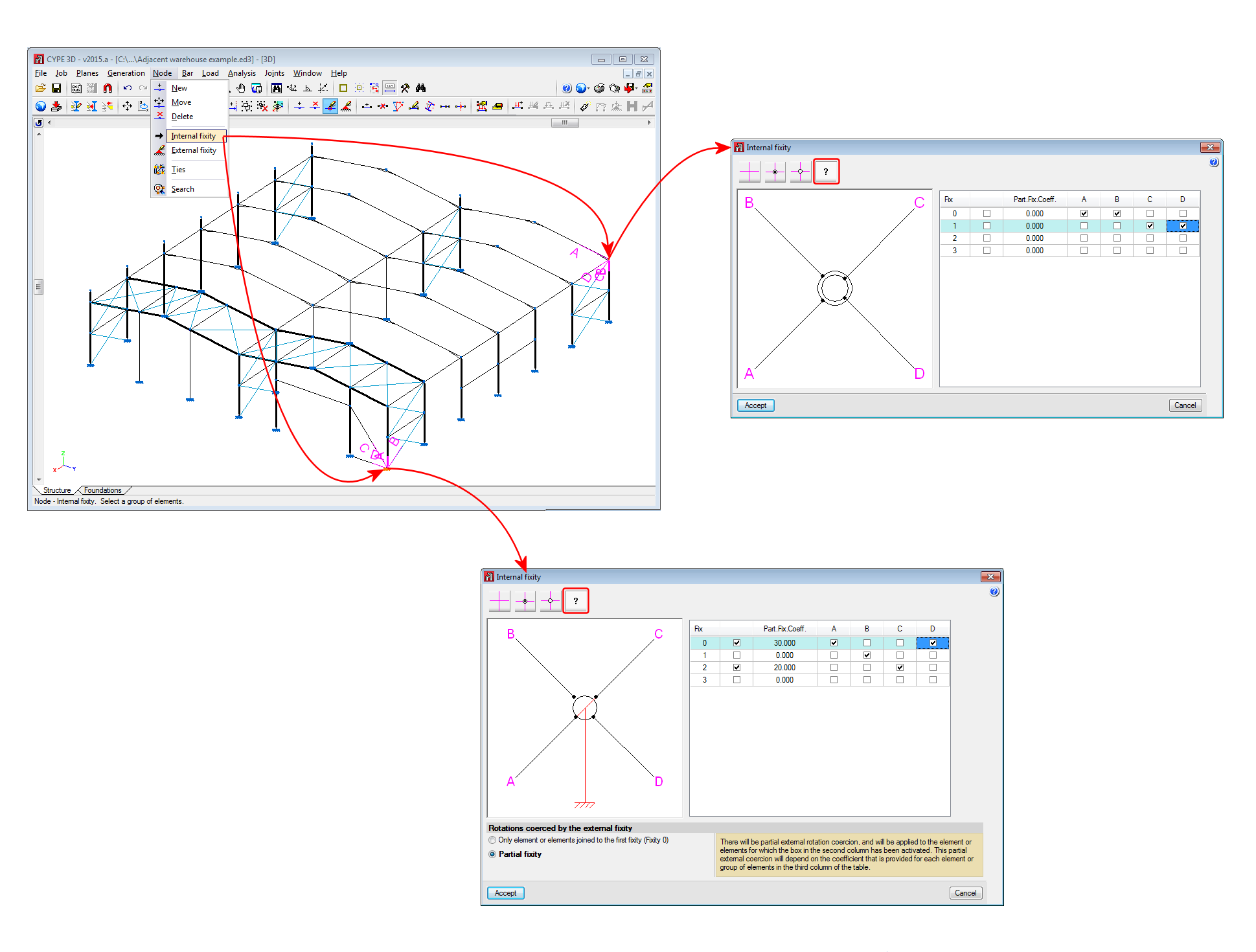
Generic node
The 2015.a version includes a new type of node. “Generic node”. With this type of node, users can define different rotation groups for the same node. Any node of a structure may be defined as a generic node by selecting the ![]() button in the “Internal fixity” dialogue box (Node > Internal fixity).
button in the “Internal fixity” dialogue box (Node > Internal fixity).
Information on how to define the internal fixities of the bars reaching the node can be found by selecting the help button ![]() in the top left-hand corner of the each dialogue.
in the top left-hand corner of the each dialogue.
If the selected node of the structure has a fixity with a coerced rotation, users can define, in the “Internal fixity” dialogue box, how the external coercion is applied to the rotation groups. In this case two options will appear in the bottom part of the dialogue with information on its operation.