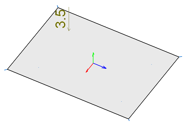
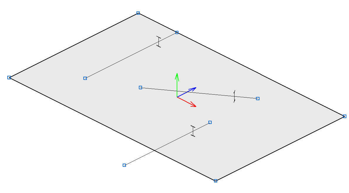
As of the 2015.1.c version, users could define shell elements in CYPE 3D. Shells connect to one another and to the rest of the structure in an explicit manner via their edges, allowing for only the following interactions to occur:
- Shell – Shell at edge
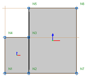
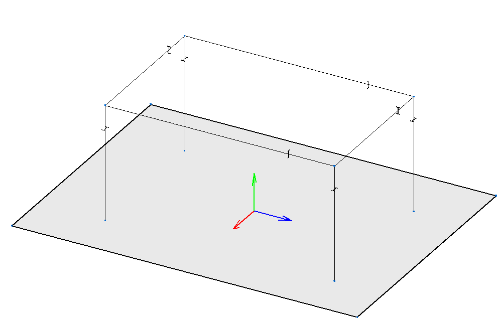
Two shells are connected to each other if they share one or more edges. In the example below, the shells are connected to one another at the edge defined between nodes N2 and N3.
- Shell – Bar end
A bar can be connected to a shell via a shared node.
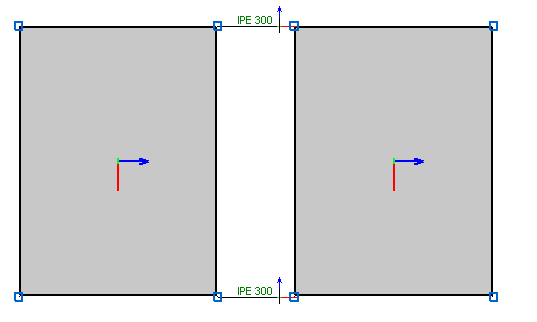
- Shell – Bar at edge
A bar is connected to a shell if it is completely contained in one of its edges.
As of the 2016.1.g version, the following additional interactions are permitted:
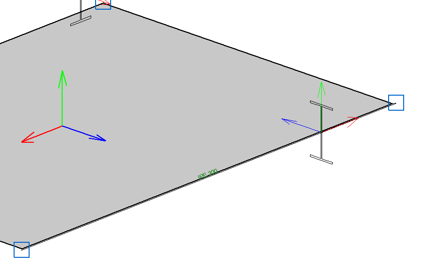
- Shell – Internal bar
A bar is connected to a shell if it goes through it. The bar can be completely or partially contained within it.
- Shell – Internal bar end
A bar is connected to a shell if one of its end nodes is contained in the shell.
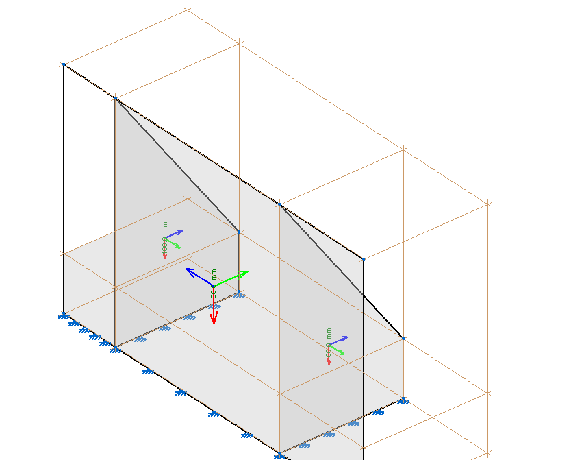
- Shell – Overlapping shell
A shell is connected to another shell if they are both contained in the same plane and overlap one another. The properties and loads of the shell with the smallest area are applied.
Under no circumstances can one shell be completely overlapped by others.
- Shell edge – Inside a shell
A shell is connected to another shell at the edge segments that are contained within the other shell.
- Shell – Node inside the shell
A node is connected to a shell if it is inside it. The editing possibilities of the internal fixity of the node are the same as for any other case. This interaction allows for point loads to be introduced on shells.