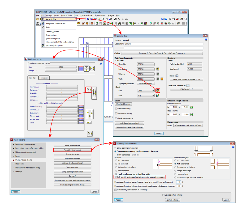
New assembly reinforcement and skin reinforcement design options have been implemented and can be used in jobs for which the concrete and seismic (if applicable) codes allow for the use of the advanced beam editor.
Assembly reinforcement design options
A new option “Only provide anchorage hooks in secondary beams if necessary” has been implemented. This option is active by default, and so has the same effect as in previous versions. If the option is deactivated, the assembly reinforcement hook will always be provided at secondary beams.
Skin reinforcement design options
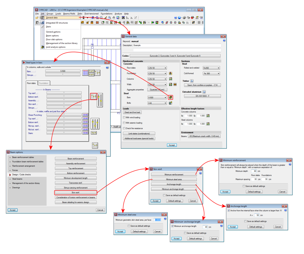
A series of design options for skin reinforcement have been implemented. In previous versions, users could only indicate as of which beam depth the skin reinforcement was to be placed, and once placed, the maximum spacing it was to have for floor slabs and beams in floor slabs and foundations had to be defined. Now these options can be edited by selecting the “Minimum reinforcement” button (skin reinforcement dialogue box – see image). Additionally, three new options have been implemented:
- Minimum steel area
Allows users to specify the minimum skin steel area at each side of the beam. If the steel area indicated by the design code is greater than that indicated in the option, the program will apply the greatest value. - Anchorage length
Allows users to anchor skin reinforcement as of the internal face of the column where the dimension of the column in that direction is greater than a user specified value . For other cases, the skin reinforcement will be anchored as of the column axis. This option avoids having to provide excessive anchorage lengths in wide columns. - Minimum anchorage length
Allows users to indicate the minimum anchorage length for the skin reinforcement. The program will check the minimum length indicated by the code and will apply the greater of the two.
Frame drawing improvements
The frame drawings in the advanced beam editor have been improved when the option to draw larger bars further away has been activated.


