Introduction
Implemented in the 2017.e version is the design of post-tensioned slabs. This improvement has been created to design the passive reinforcement of post-tensioned slabs, having calculated the forces in the post-tensioning tendons (adherent or non-adherent), and whose properties have been introduced by users.
Users can introduce the path of the tendons, their definition, their stressing loads and their losses (instantaneous and differed). The program generates two post-tensioned load patterns (one with the instantaneous loss and another with the total loss) in which the deviation loads, due to the path of the tendons are introduced. The program also creates three loadcases, two equivalent to the previously mentioned load patterns, and one hyperstatic loadcase with the total loss.
Due to the path of the tendon, forces are produced acting towards the inside of its curvature. The program automatically generates these loads for each tendon. These loads will affect the floor slabs when the local model of that floor plan is analysed. The discretisation of the floor slab during the local analysis is carried out using triangular finite elements which are adjusted to the path of the tendons.
The post-tensioning effect is taken into account when calculating the reinforcement areas required in the slab. When a tendon crosses a critical punching shear perimeter, its effect is taken into account.
Floor slabs containing tendons will be checked and will be designed as post-tensioned slabs in accordance with the ACI 318-14, ACI 318-11 and ACI 318-08 codes.
Generation of loadcases and combinations
In the dialogue box that appears when generating a local model, users can select to automatically generate post-tensioned load patterns. By activating this option, the post-tensioned load patterns, loadcases and combination groups are generated.
- Load patterns
PT Transfer with the instantaneous losses and PT Final with the total losses (instantaneous plus differed) in which the deviation loads produced by the path of the tendons will be introduced. - Loadcases
Three loadcases are created, one equivalent to each of the previously mentioned loadcases and a third hyperstatic loadcase with the total loss. - Combination groups
Four combination groups are created: PT Flexural strength (Ultimate), PT Service (Initial), PT Service (Normal) and PT Service (Long term). Each post-tensioned state will be assigned one of these combination groups.
Implemented tools
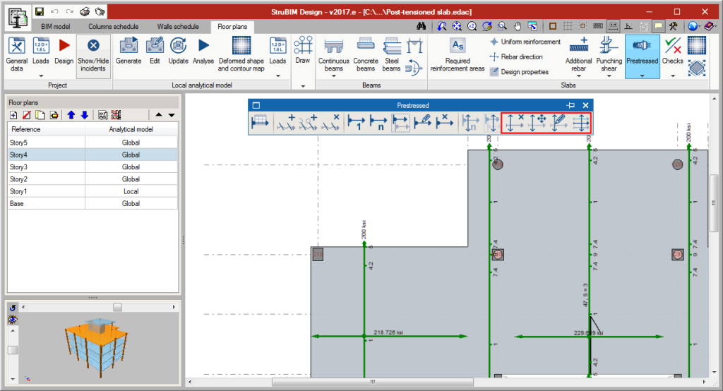
- Flexure lines
The intersections, on plan, of the flexure lines with the paths of the tendons represent the points where the tendon curves to reach its maximum elevation.
Flexure lines can be introduced between two points and on reference lines. - Tendon introduction
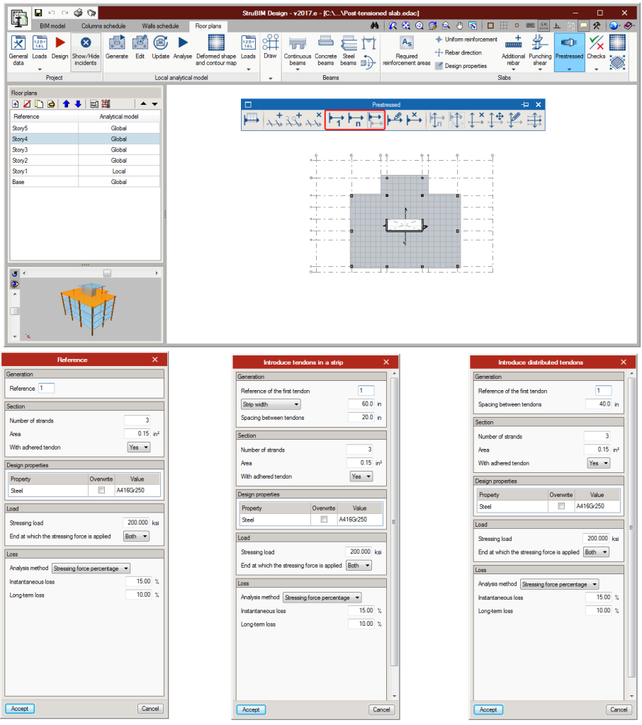
There are several tendon introduction options: Introduction of a single tendon, introduction of concentrated tendons and introduction of distributed tendons. The difference between these options lies in the way the number of tendons that have to be introduced are defined.- One tendon
One tendon is introduced between two points.
- Concentrated tendons
El usuario indica la separación entre los tendones y el número de ellos o el ancho de banda.
- Distributed tendons
Users indicate the spacing between tendons. Once the dialogue box has been accepted, the path of the tendons is defined graphically, and the strip width along which they are to be placed.
- Section
Number of strands, their cross-sectional area and their type (adherent or non-adherent). - Tendon material
- Load
Transfer load pattern, final load pattern, stressing load and end at which the stress is being applied. - Stressing loss
Three options appear to define the stressing loss:
- Stressing force percentage
- Specified value
- Detailed analysis, based on the friction coefficient due to the curvature, friction coefficient due to accidental deviation, spacer penetration, loss due to elastic shortening of the concrete, loss due to creep of the concrete, loss due to concrete shrinkage and loss due to steel relaxation.
- One tendon
- Tendon schedule
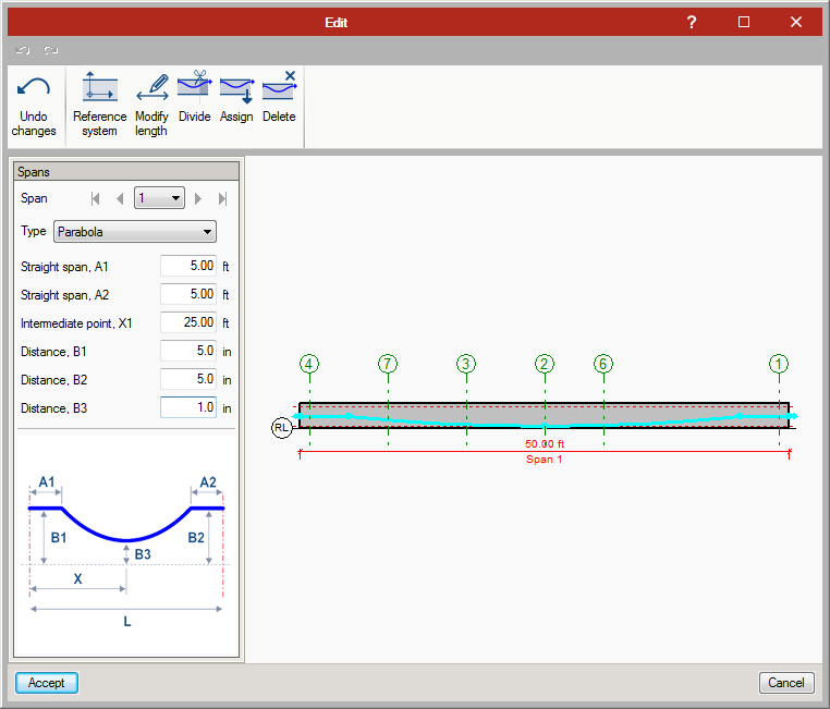
The different properties of the tendons can be edited in the tendon schedule (previously defined during the introduction), as well as the elevations.
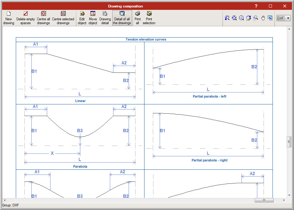
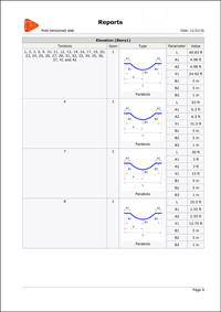
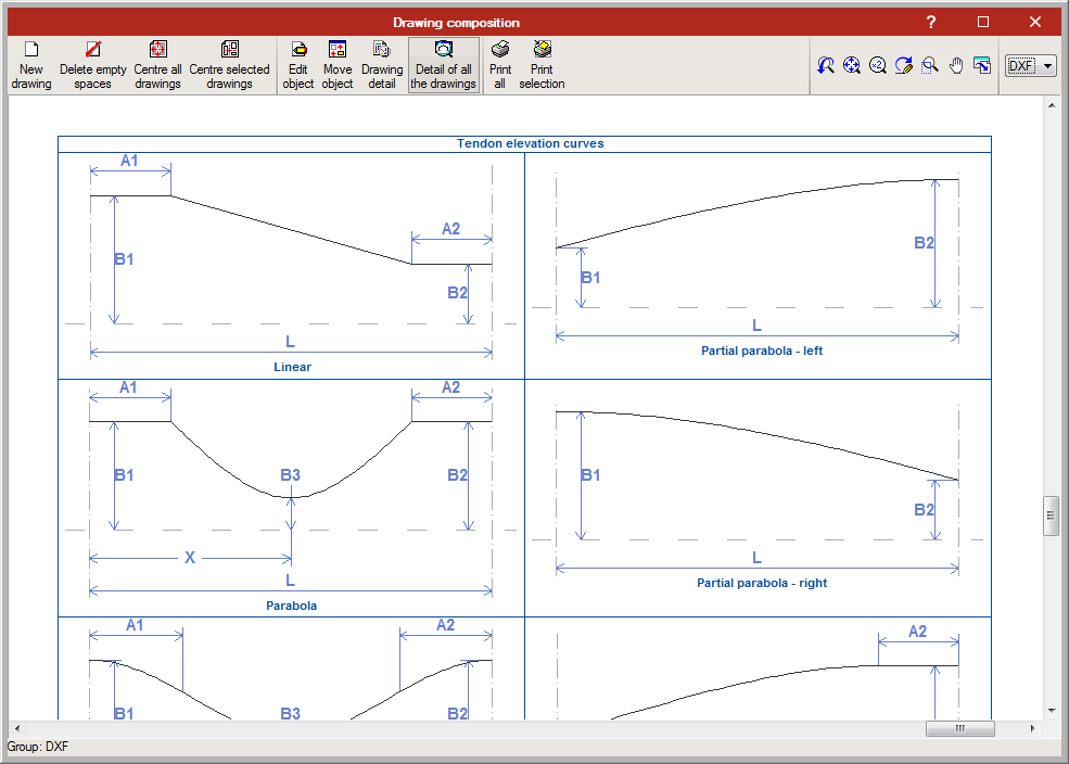
By editing the diagram, users can modify the path of the tendons on the elevation view of the slab. There are several types of elevations that can be assigned to each tendon span:
- Linear
- Parabola
- Reverse parabola
- Harped one point parabola
- Harped two point parabola
- Partial parabola - left
- Partial parabola - right
- Partial rev. parabola - left
- Partial rev. parabola - right
- Representation tools
The tendon groups (concentrated or distributed) can be represented as being grouped or ungrouped. There are label management tools, in case users choose to represent the tendons as grouped. These tools allow user to add, edit, move, and delete labels as well as select the visible tendon of the group. - View options
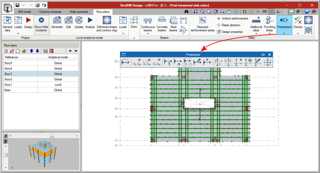
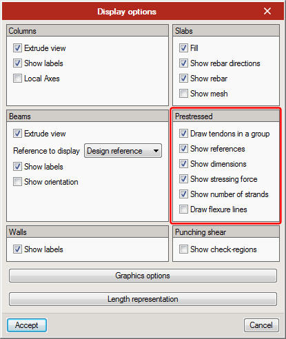
From the Draw menu, users can access the View options, where several options have been added to view prestressed related elements.
Results output
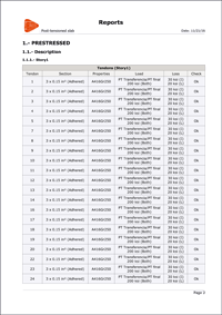
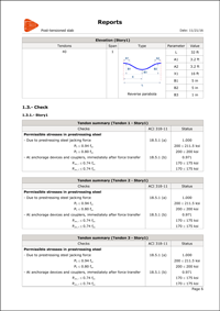
Different reports are generated indicating the properties, elevation geometry and checks of the tendons.
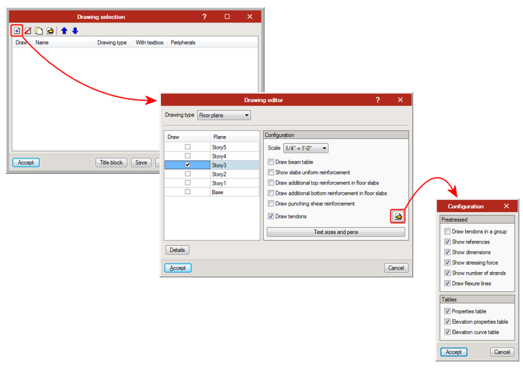
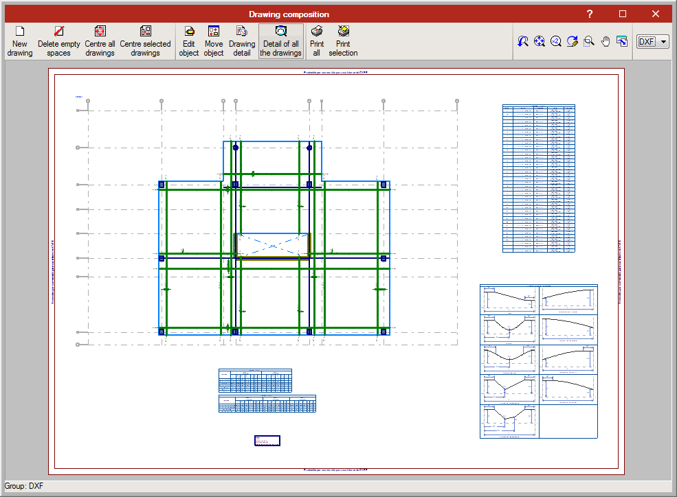
The program also generates floor plans with the tendon distribution and dimensions selected by users in the drawing configuration. Users can also include the Properties table, the elevation properties table and elevation curves table.


