As of the 2018.a version, CYPE 3D includes the analysis, design and check of prequalified connections in accordance with ANSI/AISC 358-10 (Prequalified Connections for Special and Intermediate Steel Moment Frames for Seismic Applications) and ANSI/AISC 341-10 (Seismic Provisions for Structural Steel Buildings).
Prequalified connections are applied to Special Moment Frames (SMF) and Intermediate Moment Frames (IMF) as indicated in the ANSI/AISC 341-10 code.
It is possible to define prequalified connections in projects in which the rolled and welded steel code: ANSI/AISC 360-10, has been selected.
Implemented prequalified connections
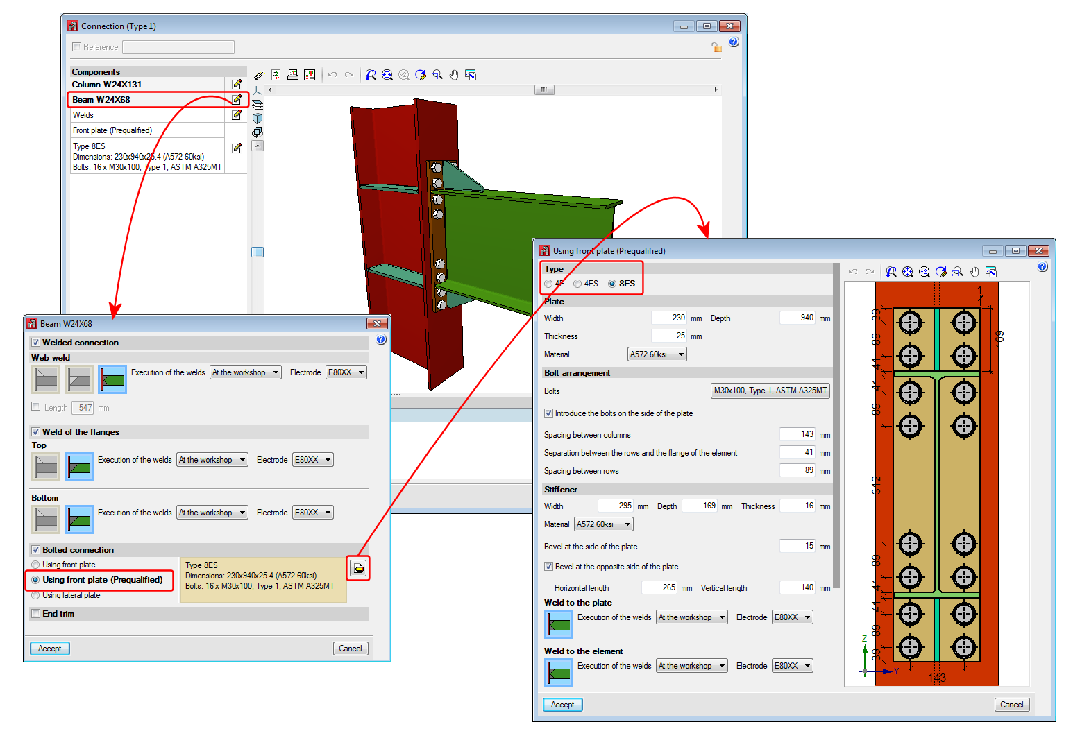
The prequalified connections that have been implemented in the program are:
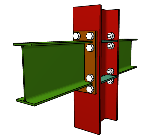
- 4E four-bolt unstiffened
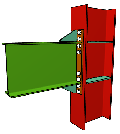
- 4ES four-bolt stiffened
- 8ES eight-bolt stiffened
Nodes with interaction of several beams
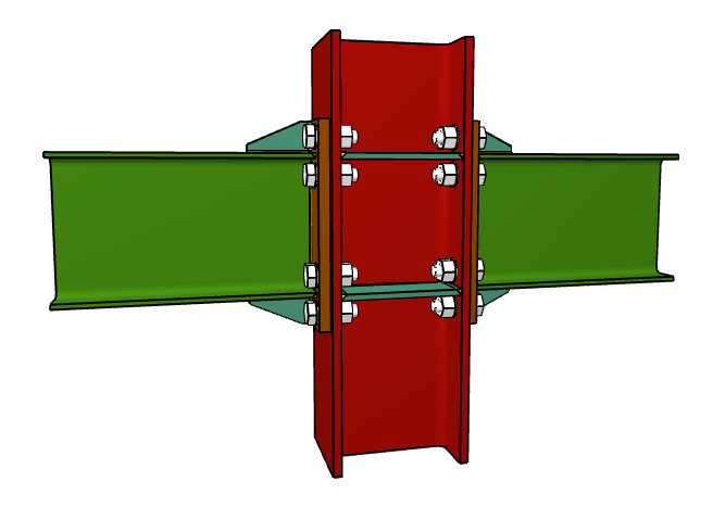
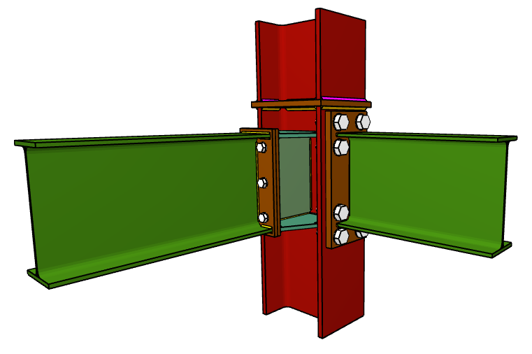
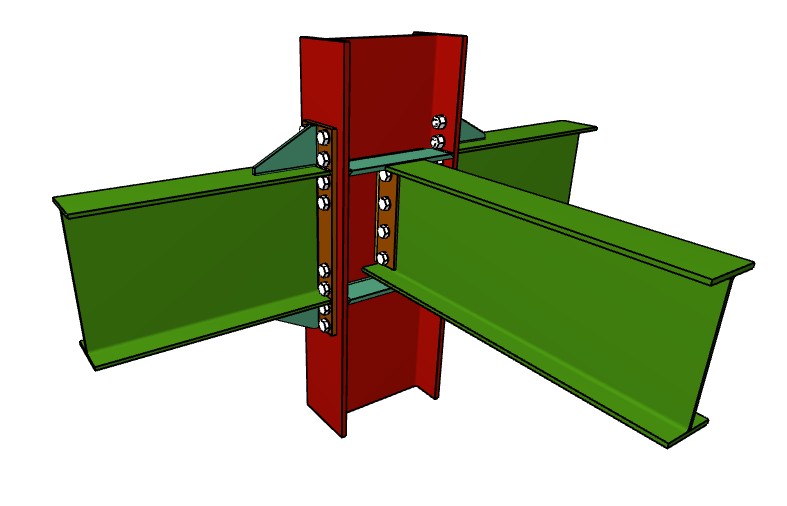
Column-beam prequalified connections can be part of a node interacting with connections of other beams, which can or cannot be prequalified connections. For example:
- Prequalified 4E connection to the flange of the column and moment connection to the web of the column and ordinary front plate.
- Prequalified 8E connections to the flanges of the column and pilled connection using lateral plate to the web of the column.
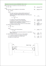
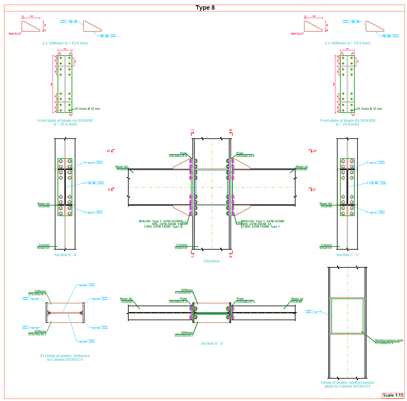
Checks and drawings
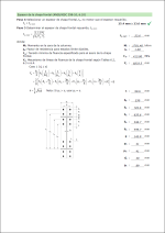
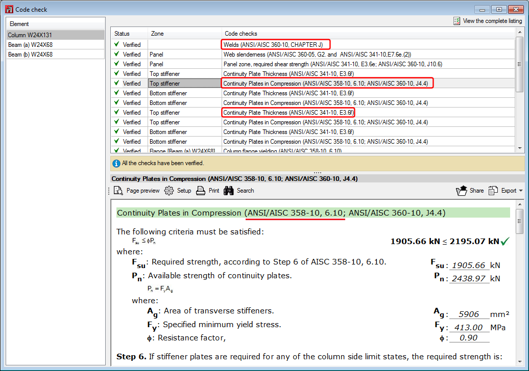
As well as the checks carried out on the connection in accordance with the ANSI/AISC 360-10 rolled steel code, specific checks of the ANSI/AISC 341-10 and ANSI/AISC 358-10 codes are carried out. The check report displays the chapter of the code in accordance which the check is performed.
Operation in CYPE 3D
For CYPE 3D to carry out the analysis, design and check of prequalified connections of columns and beams, the following conditions must be met:
- The rolled steel code must be ANSI/AISC 360-10
- The bars reaching the node must be column-type and beam-type
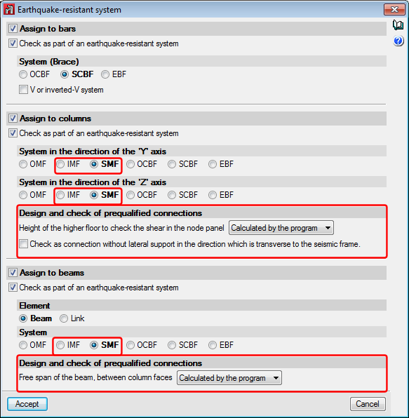
- The earthquake-resistant system assigned to the bars reaching the node must be that of Special Moment Frames (SMF) or Intermediate Moment Frames (IMF).
When the type of earthquake-resistant system is assigned to columns and beams, it is also possible to:
- Define the height of the higher floor to check the shear in the node panel
This parameter can be calculated by the program or established by users. It is used to calculate the shear of the column above that would affect the check of the shear in the node panel. - Check as connection without lateral support in the direction of the seismic frame
Users can choose whether or not to carry out this option depending on the bracing there may be in the elements of the connection. This check is only carried out for SMF frames. - Free span of the beam, between column faces
Value required to calculate the moment at the face of the column, this value can be calculated by the program or provided by users.