
Introduction
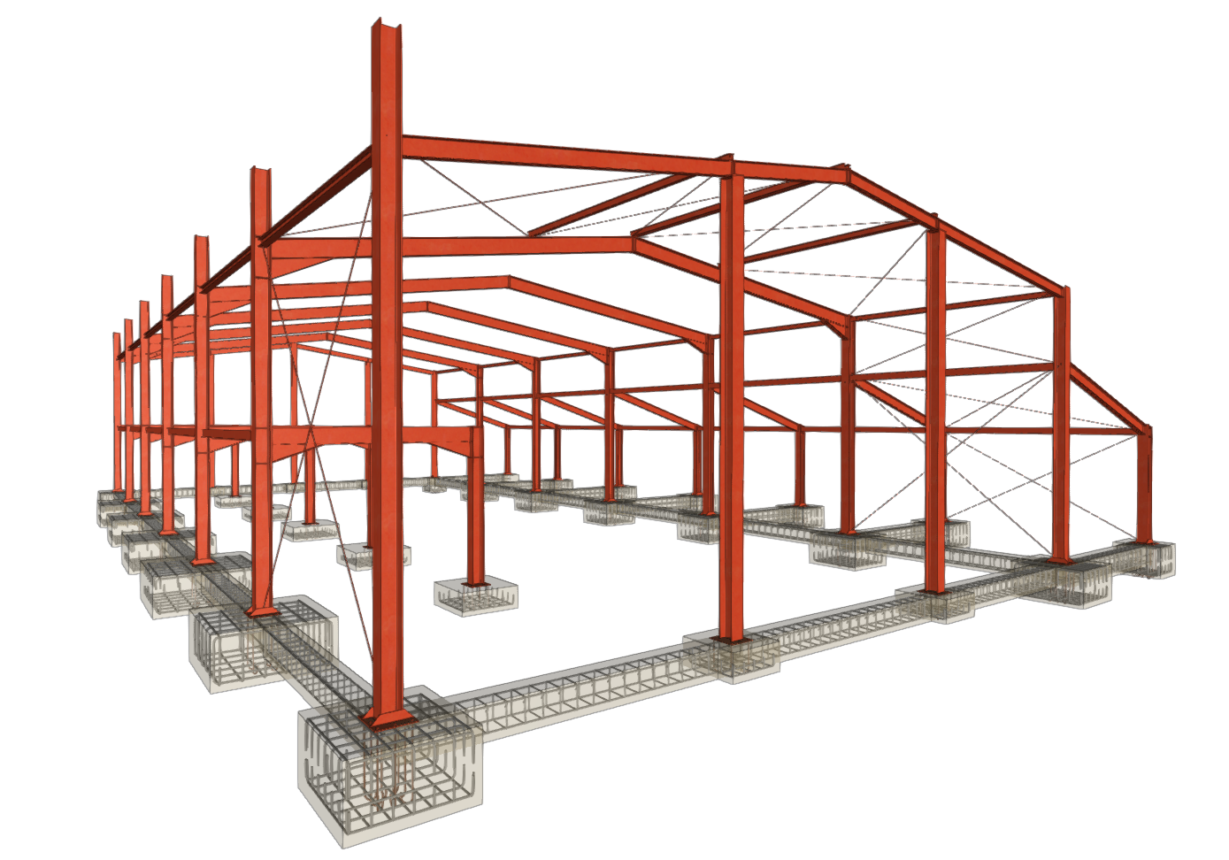
CYPE 3D is a program created to carry out the analysis of 3D structures made of steel, concrete, composite steel and concrete, aluminium, timber, or any other material, including the design of connections (welded and bolted connections of rolled and reinforced steel sections in I-shaped and hollow sections) and the foundation using baseplates, footings, pile caps, tie beams, and strap beams.
As well as checking and designing structures made up of nodes and bars, the program can add shells (flat 2D elements with a constant thickness and polygonal perimeter that are broken down into finite elements) to analyse their stresses and strains.
The fire resistance of sections can be checked, the structure can be analysed for seismic resistance, and, thanks to the integration of the OpenSees analysis engine, advanced analyses can be carried out, such as determining the critical load factors for buckling, modal analysis of vibrations or pushover analysis.
The program can generate design reports, including checks performed according to different regulations for each element, and structural drawings. Models created with CYPE 3D can also be imported into CYPECAD as integrated 3D structures for joint design, as well as exported to CYPE Connect for designing and analysing connections in detail.
Getting started: creating new jobs, workflows, and examples
When you start the program and create a new project, you are presented with various options, such as creating an empty project to start from scratch or automatically importing data from models saved in IFC format files.
The program then allows you to configure the general project data and access the main working interface.
The geometry and loads of the structure can also be automatically generated in CYPE 3D from the data entered in the Portal frame generator, or the geometry can be imported from information saved in .dxf, .dwg or .txt files.
The following link provides detailed information on the options that appear in the initial process of creating new jobs, instructions on possible workflows and the general sequence of data entry and output, as well as a gallery of examples of structural models developed with the program.
Setting up the work environment
The program's working environment has two separate tabs: "Structure" and "Foundation", accessible from the bottom left of the screen.
In turn, within the "Structure" tab there are different tabs at the top ("Job", "Geometry", "Properties", "Load", "Connections", "Analysis", "Reinforcement" and "Windows"), which follow the sequential order of entry, definition and analysis of a structural model.
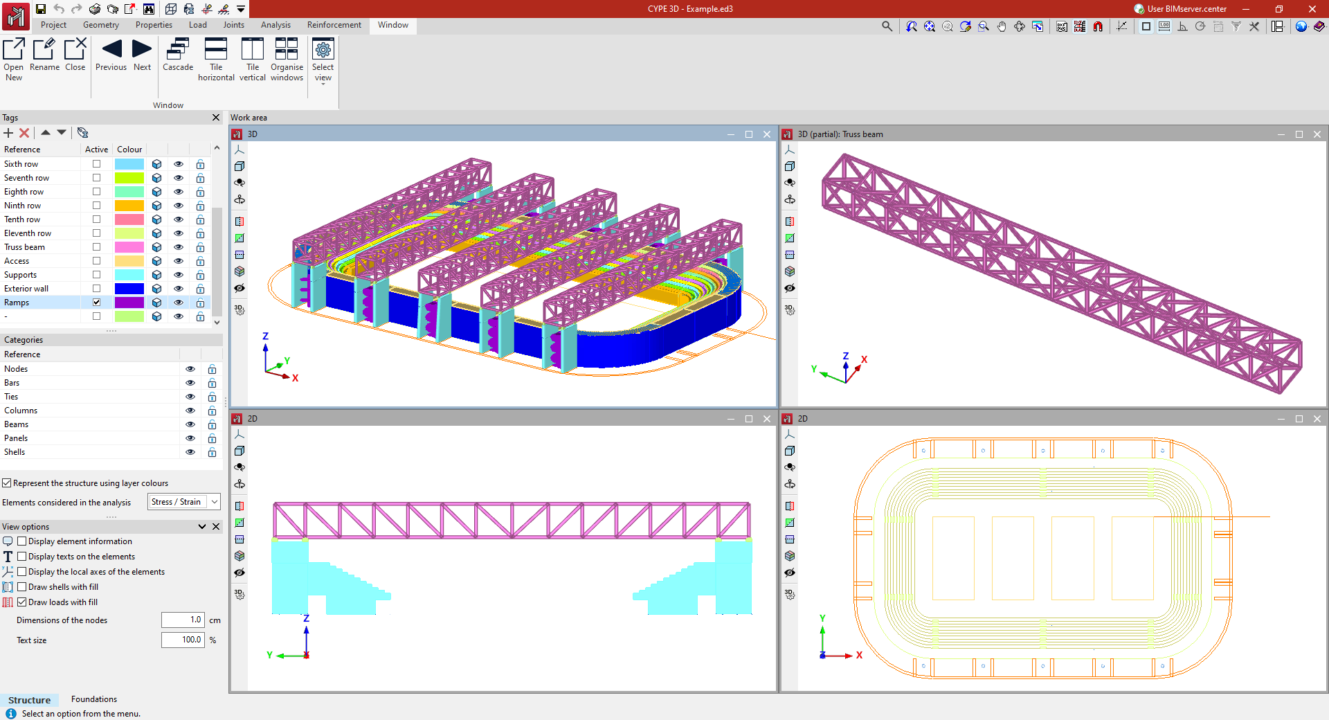
The interface consists of the following parts:
- The top of the main toolbar contains different features depending on which tab is open.
- Further down, in the work area, all project elements are entered, edited, and viewed. You can choose how elements are drawn: schematically or in three dimensions. The program allows you to define different display windows (3D or 2D), which facilitates work on the structure. To do this, use the tools in the "Window" tab.
- On the left side of the "Structure" tab are the main tools for defining project tags and managing the visibility of categories, as well as other display options.
These panels act as dockable windows that can be customised to adapt the workspace to the needs of the project.
The following link provides detailed information about the program's working environment and the options available in the "Window" tab.
Setting up the project data
The "Project" tab contains general options related to job configuration, element library management and numbering.
It also offers additional options for viewing the 3D view, obtaining reports on a selection of elements or linking the project to a BIMserver.center project.
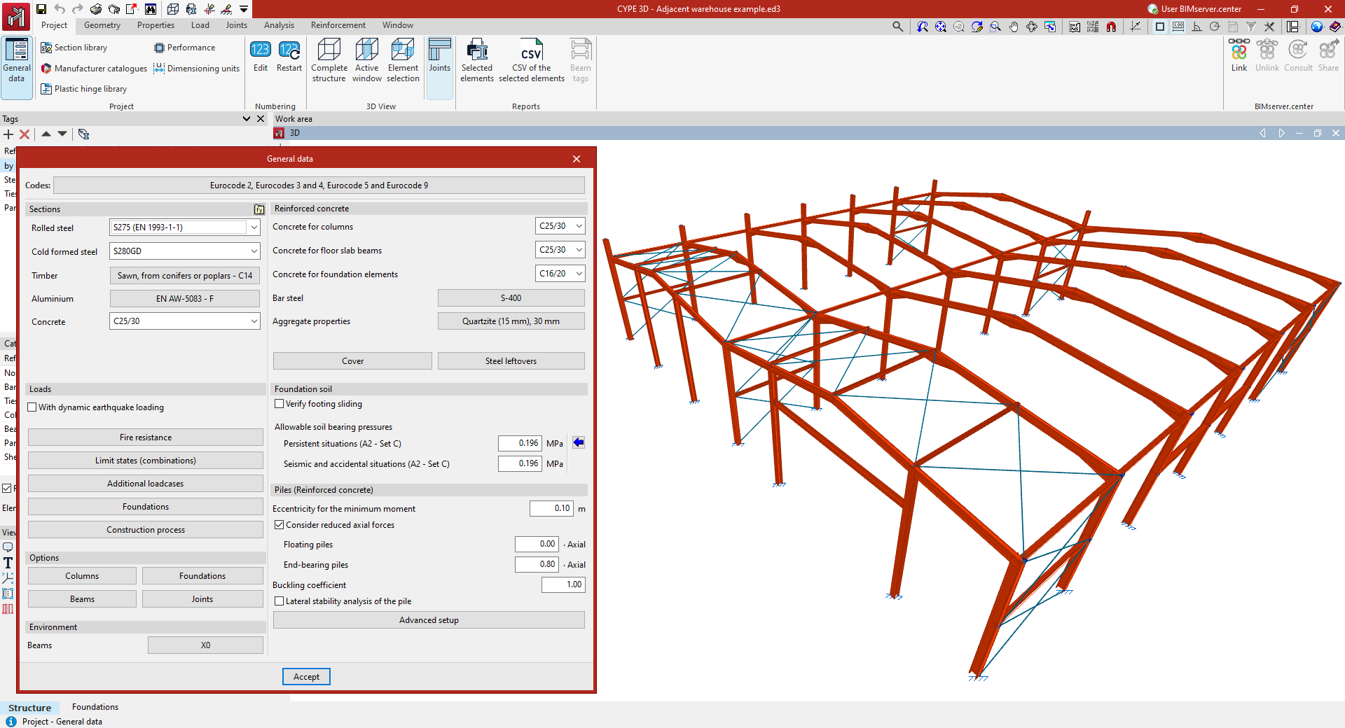
Access to the general project data settings allows you to adjust aspects such as the following:
- the regulations to be verified;
- the materials used in the construction;
- the loadcases and combinations of loadcases, including data relating to seismic activity;
- and the adjustment of other analysis configuration parameters, such as the reinforcement tables used or the design options for the different elements of the job.
The following link provides detailed information about the options offered by the program in the "Project" tab.
Defining the geometry of the structure
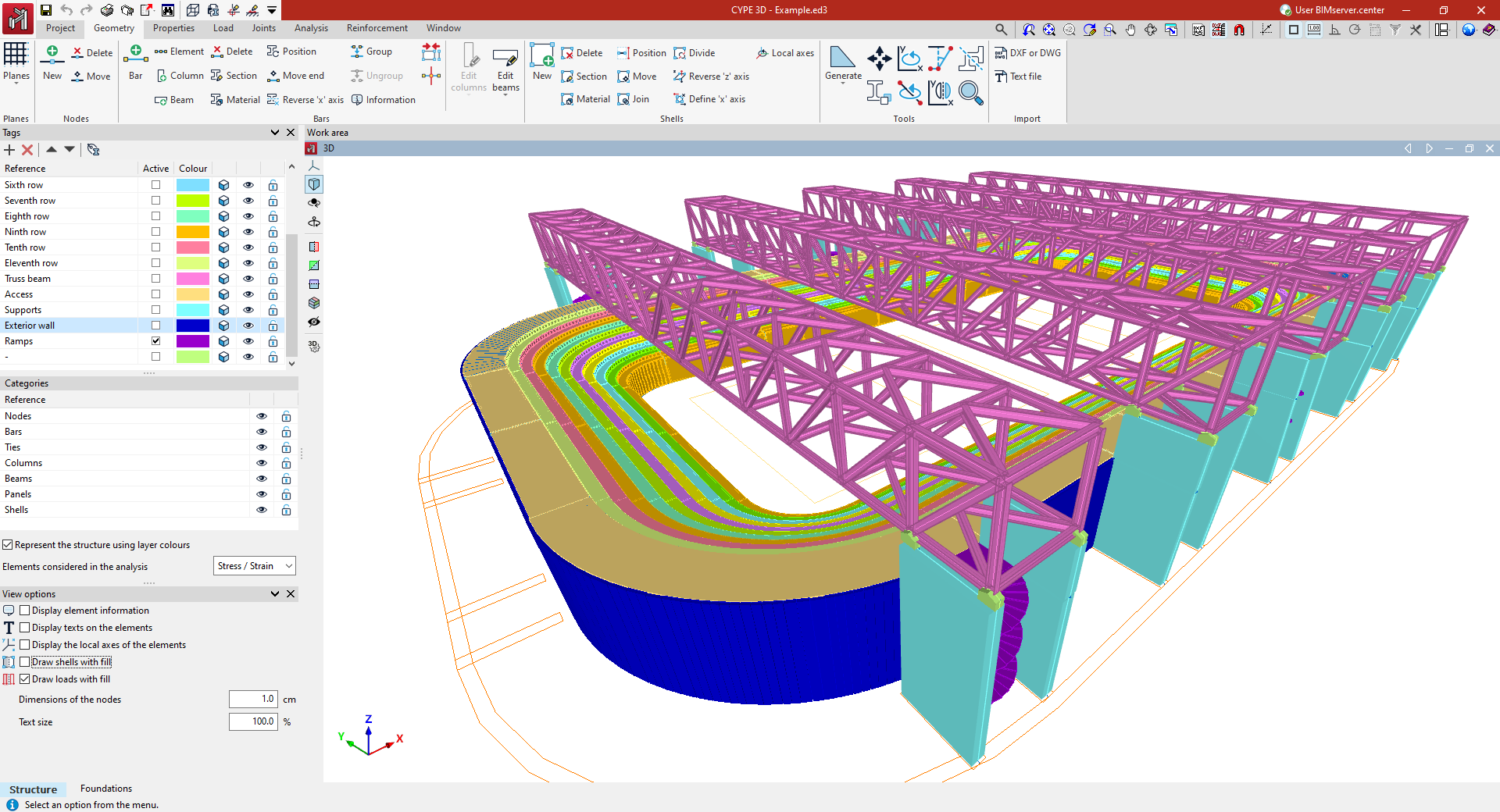
The "Geometry" tab contains options for defining reference planes and entering the geometry of the nodes, bars, and sheets of the structure in the model.
Nodes, bars and plates can be entered in various ways in the work area windows using different support elements such as grids, reference drawings and lines, dimensions, templates and/or coordinate systems.
In addition, during this geometry definition process, the section and material of each of the bars and plates entered must be specified. It is possible to enter elements such as generic bars, columns, beams or braces. In terms of available materials, it is possible to enter steel bars, concrete bars, mixed concrete and steel bars, aluminium bars, timber bars, or generic material bars.
Additionally, tools are provided for editing the elements entered and their geometric adjustment, as well as for the automatic generation of predefined geometries or from the import of .dwf or .dwg files and text files.
The following link provides detailed information on the options offered by the program in the "Geometry" tab.
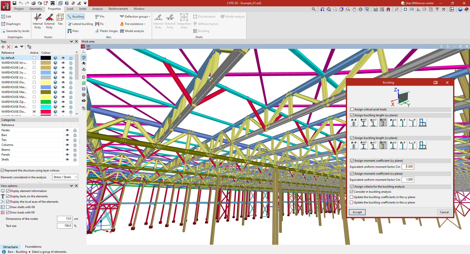
Editing the properties of structural elements
The "Properties" tab contains options for defining the characteristics of structural elements such as nodes, bars, and plates.
These features include:
- in the nodes, the definition of internal and external connections, and ties;
- in the bars, the adjustment of buckling and lateral buckling coefficients and/or lengths, the introduction of bracing pairs, and the definition of joints and end fixings, plastic hinges, and deflection groups;
- in shells, the definition of internal and external connections is allowed, as well as force integration bands;
- this tab also includes options for entering, generating, and editing rigid diaphragms in the model.
The following link provides detailed information about the options offered by the program in the "Properties" tab.
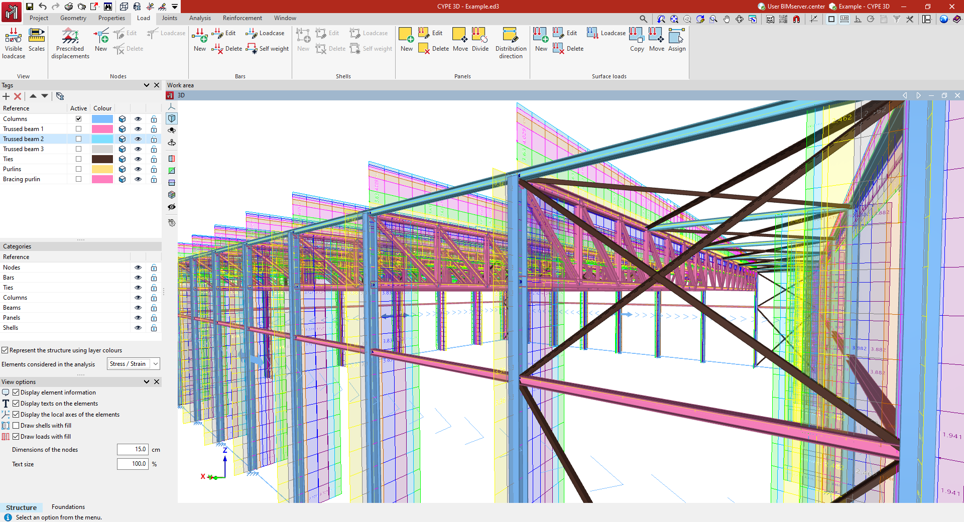
Entering and editing loads on the structure
The "Loads" tab contains options for viewing, entering, and editing loads on structural elements.
These include loads on nodes, loads on bars, loads on shells, load panels and surface loads, which may occupy all or part of a panel.
The loads entered can be associated with the desired load hypothesis and are defined by their type, value, and direction. It is also possible to apply loads due to temperature increases, apply prescribed displacements and rotations, or manage the automatic generation of dead loads.
The following link provides detailed information on the options offered by the program in the "Loads" tab.
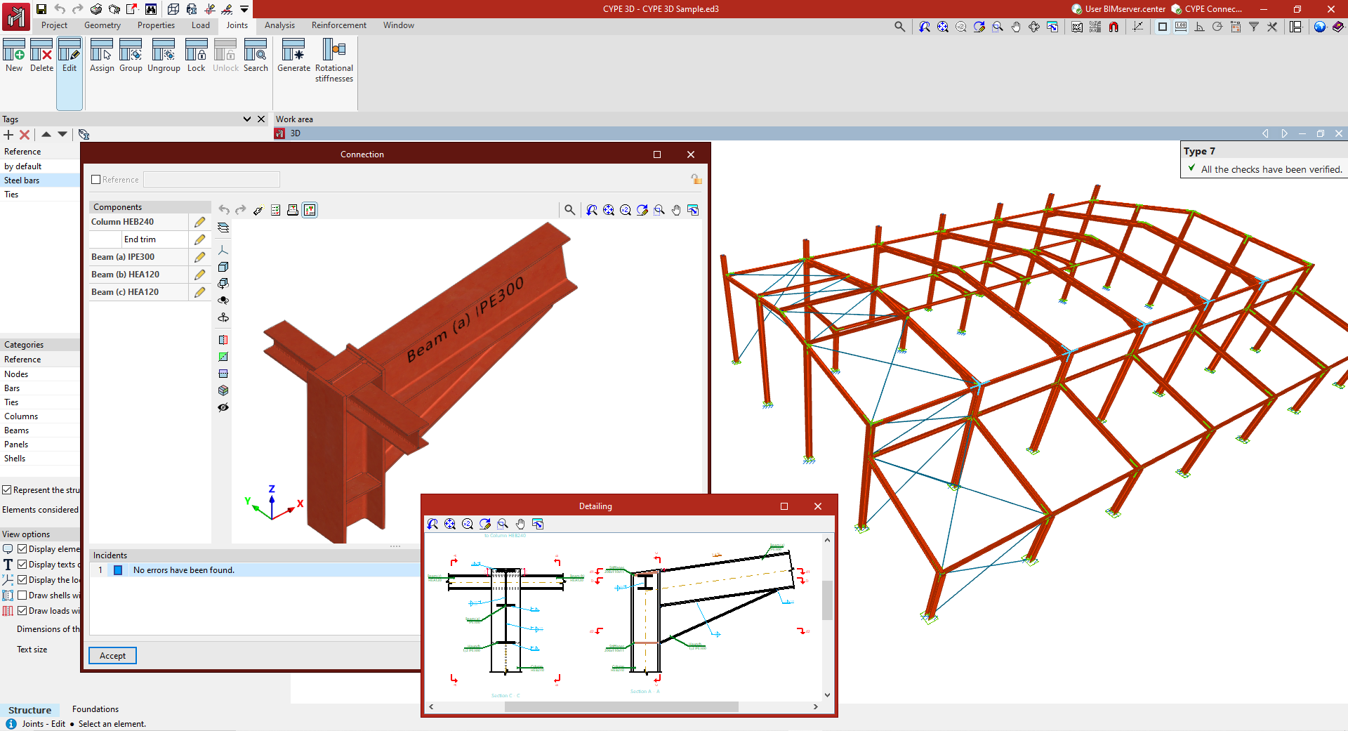
Designing and analysing joints
The tools for designing and analysing structural joints are located in the "Joints" tab.
Here, you can manually enter joints at nodes, at the ends of parts, or between a group of selected parts, or generate joints automatically.
You can also edit their components and access tools for analysing and designing each joint individually, as well as for obtaining detailed regulatory compliance reports or detailed drawings.
The following link provides detailed information about the program's options, located in the "Joints" tab.
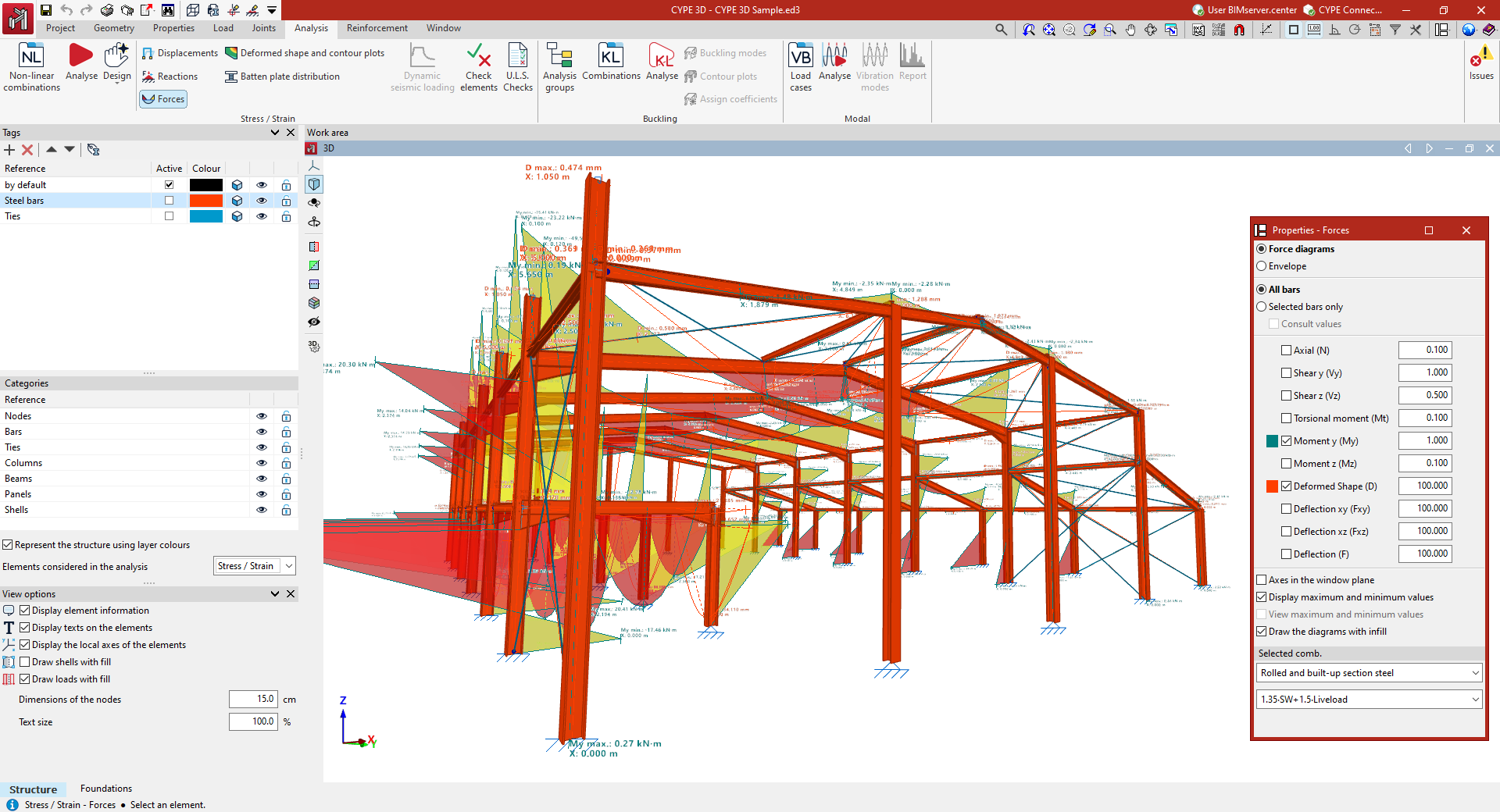
Analysis, checking, and results review
The "Analysis" tab contains the tools used to analyse and design structural elements, as well as to view analysis results.
The following analysis results are available:
- Node displacements
- Reactions at supports
- Forces in bars and integration strips
- Deformations and contour plots
- Checks carried out
- Detailed reports of ultimate-limit-state checks
In addition to stress-strain analysis, the program can carry out advanced analyses, such as linear buckling analysis, modal vibration analysis and pushover analysis.
The options offered by the program can be viewed in detail under the "Analysis" tab at the following link.
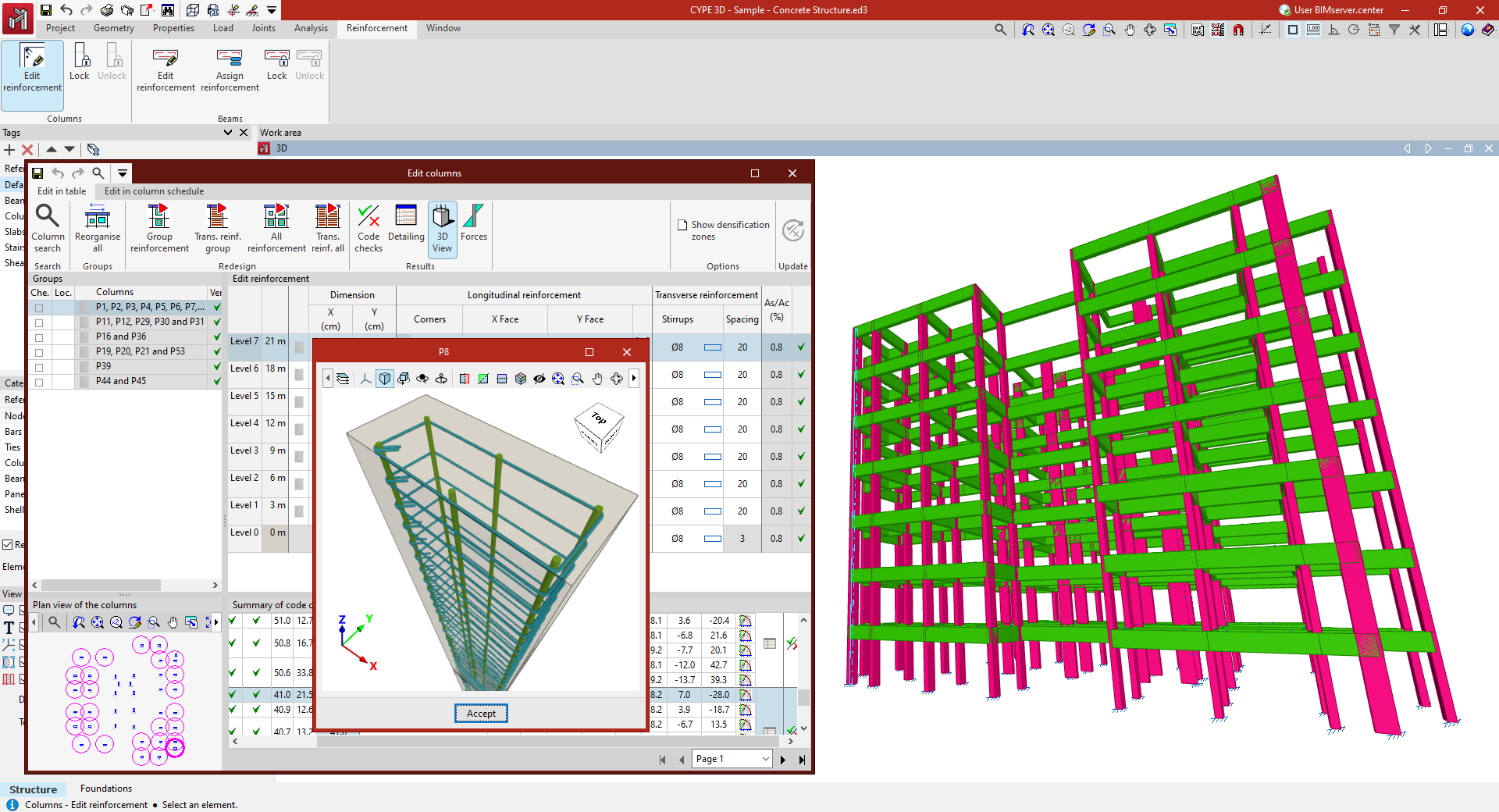
Defining and editing reinforcement
In the "Reinforcement" tab, the program offers a series of utilities to consult and modify the reinforcement and sections of the columns and beams entered in the model.
Using a series of editors, you can consult the forces, dimensions and checks automatically performed by the program on all the columns and beams in the job and on all their spans.
In addition, the reinforcement or sections used can be adjusted, and the modifications made can be checked, generating detailed regulatory check reports.
The following link provides detailed information on the options offered by the program in the "Reinforcement" tab.
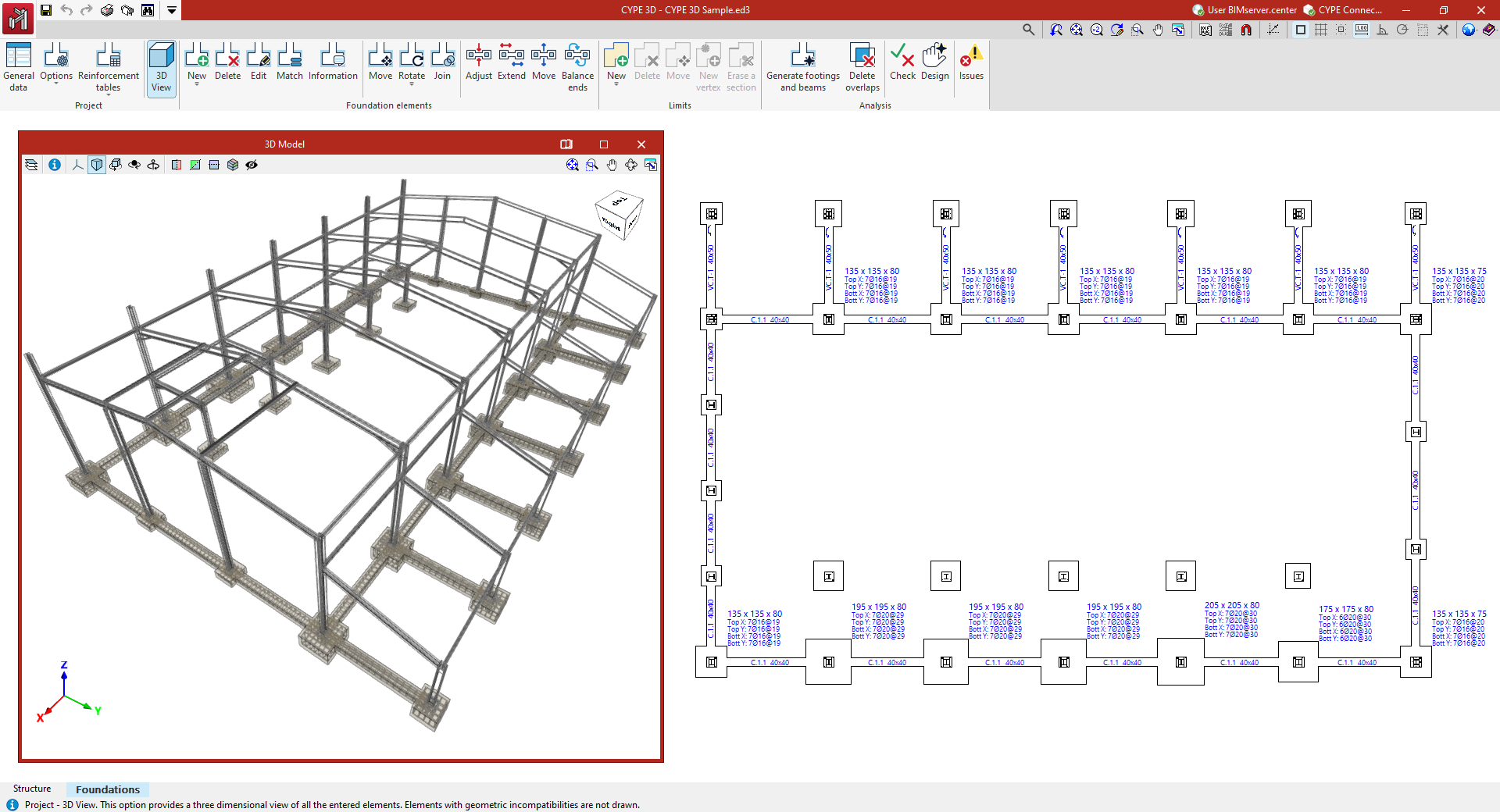
Designing and analysing the foundation
After completing the work in the "Structure" tab, go to the "Foundation" tab, where the foundation elements of the structure are designed and analysed.
To do this, configure the general foundation data, the options for its analysis and design, and the reinforcement tables.
Next, its components are entered into the plan, such as footings, beams, tie beams and strap beams, or the automatic generation of footings and beams is used.
Finally, the calculation, verification and dimensioning of all the foundation elements is carried out. If necessary, the elements can be edited and adjusted, and the modifications made to them can be checked.
The following link provides detailed information on the options offered by the program in the "Foundation" tab.
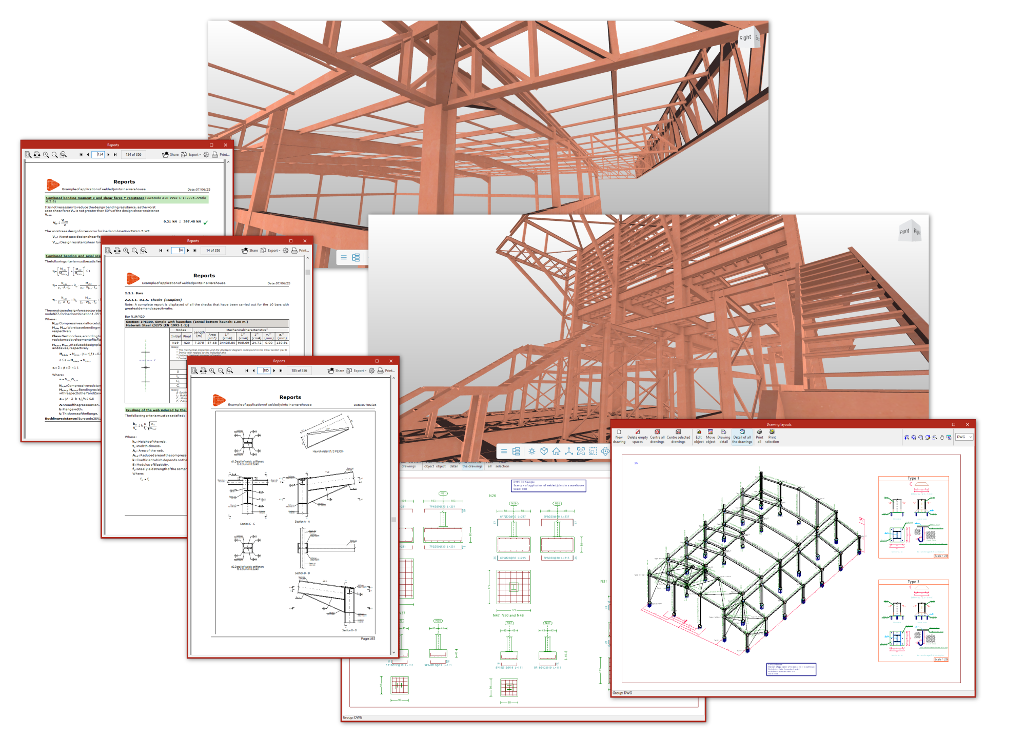
Printing documents and exporting data
After analysing the project, the program generates the following documents:
- Analysis reports, including checks performed according to different codes for each element, which can be printed directly or exported to HTML, DOCX, PDF, RTF or TXT formats.
- Project drawings in DWG, DXF or PDF format.
- CSV files can also be obtained with data such as node geometry or forces by loadcase, combinations and bar envelopes.
In addition, you can share the information generated by the program with a BIM project on the BIMserver.center platform using IFC and GLTF files, among others. This way, it can be used by other apps linked to the project, such as:
- CYPE Connect, which enables detailed connection analysis
- Autodesk Revit (using the Open BIM - Revit plugin), which enables the reading of elements included in the structural IFC and the conversion of some of them to native format.
Additionally, if the CYPE 3D project is linked as an integrated structure in CYPECAD, the following will be possible from this program:
- Obtaining bills of quantities for structural elements, which can be exported directly to Arquimedes or to files in FIEBDC-3 format to be processed by other quantity surveying programs;
- When exporting to Arquimedes, generating the rest of the documents linked to the CYPE Cost Database, such as the specifications, the ten-year maintenance assessment, the health and safety study, waste management, life cycle analysis and the building use and maintenance manual.
The following link provides detailed information on the options offered by the program for printing documents and exporting the data obtained after the analysis.
Table of contents
Complete your CYPE 3D journey by exploring the other available sections:
- Introduction
- Start: creating new projects, workflows, and examples
- Setting the work environment
- Setting the job data
- Defining the structure’s geometry
- Editing the properties of structural elements
- Entering and editing loads on the structure
- Designing and analysing connections
- Analyses, checks, and results
- Defining and editing reinforcement
- Designing and analysing foundation
- Printing documents and exporting data


