CYPE 3D is an agile and efficient program designed for analysing three-dimensional structures of concrete, steel, composite concrete and steel, aluminium, timber or any other material bars; and of shells (flat two-dimensional elements of constant thickness whose perimeter is defined by a polygon). It includes the design of joints (welded and bolted joints rolled and welded steel I-sections and hollow sections) and their foundations with baseplates, footings and pile caps.
On this webpage, a detailed definition of bars as generic structural elements is provided.
For information on other properties in CYPE 3D, please visit the CYPE 3D webpage.
Bar structure types in CYPE 3D
CYPE 3D allows users to enter bars made of concrete, steel, composite steel and concrete, aluminium, timber or any other material.
The program designs the section and provides its optimum size for bars made of steel, aluminium, timber or concrete (if they have been defined as "Column" or "Beam" type structural elements).
Composite steel and concrete bars can be defined if they have been introduced as "Column" type structural elements and, although they are not designed automatically, they are checked by the program with the properties that have been indicated by users.
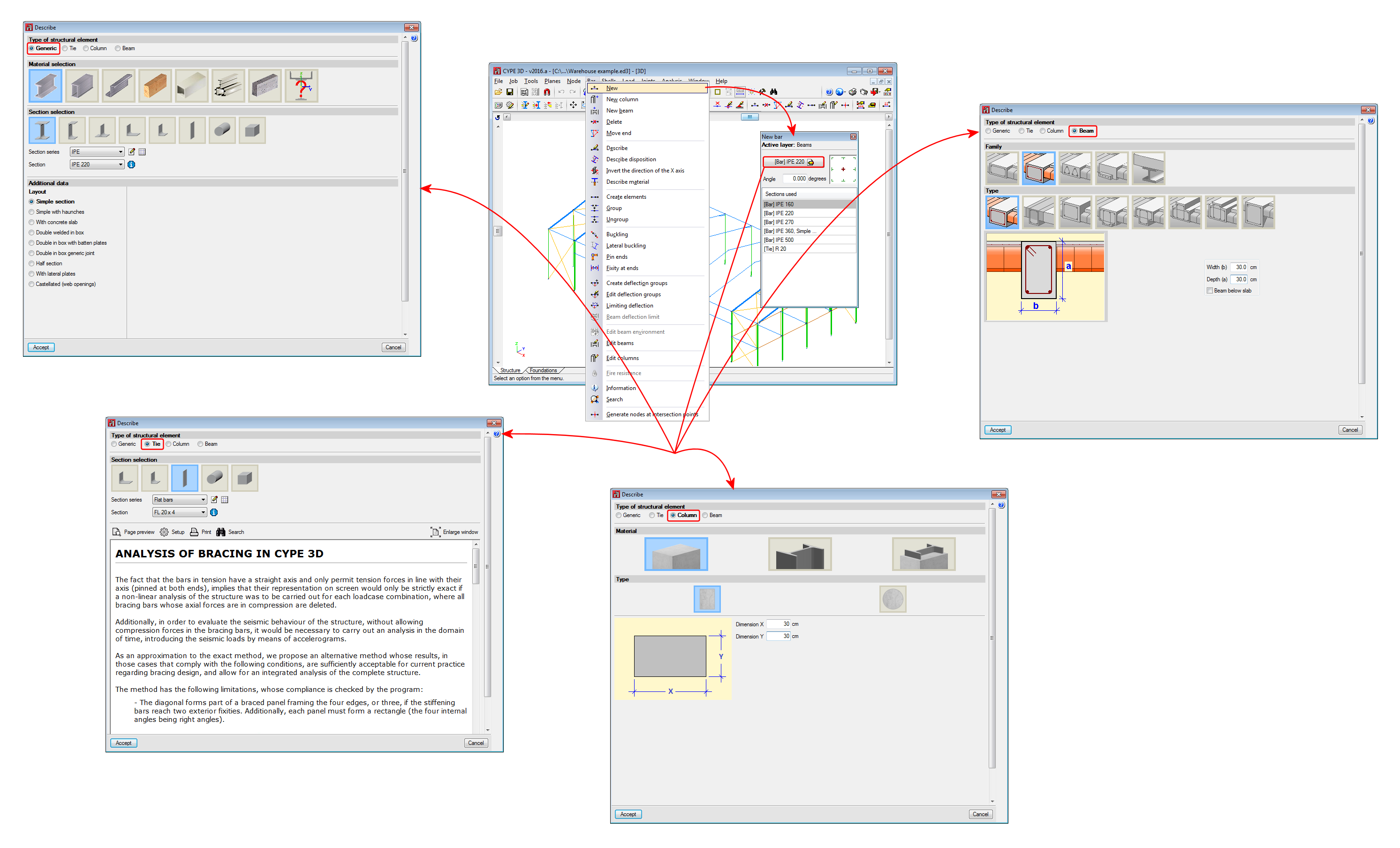
Introducing column and beam concepts in CYPE 3D means that the bars in the model are characterised as belonging to a type of structural element. In CYPE 3D, as of version 2016.a, bars are assigned to one of the following types of structural elements: "Generic" type structural elements, "Tie" type structural elements, "Column" type structural elements and "Beam" type structural elements.
This webpage discusses the definition of bars as "Generic" type structural elements. In order to consult the properties of bars defined as other types of structural elements, please consult the following links: "Tie" type structural elements, "Column" type structural elements and "Beam" type structural elements.
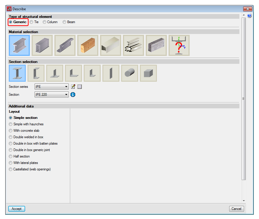
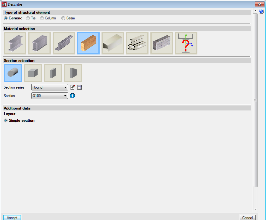
"Generic" type structural elements
Elements defined this way do not have a specific structural role in the program. They can be assigned the following material:
- Steel (rolled, welded or cold-formed)
- Aluminium
- Timber
- Reinforced concrete
- Any other user-defined material
The program automatically designs the bars if the material they have been assigned is steel; aluminium or timber.
If the assigned material is reinforced concrete or a user-defined generic material, the program analyses the forces to which these bars are exposed and displays the results by simple loadcases, by combinations or by envelopes; but their sections are neither checked nor designed. To check and design reinforced concrete bars in CYPE 3D, they must be defined as "Column" type or "Beam" type structural elements.
Steel bars
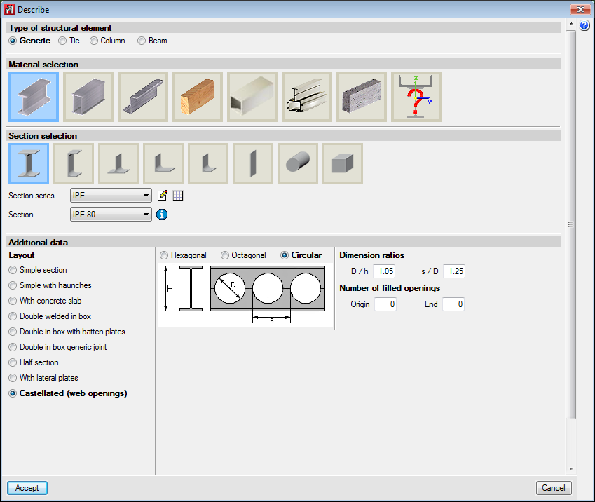
For steel bars, the program uses rolled, cold-formed and welded steel sections managed from its extensive database made up of a large variety of sections available from main manufacturers and profile catalogues. Composite sections can be created based on simple sections using a welded connection, batten plates, lateral plates, etc. Haunches at bar ends; variable section bars; steel castellated beams with hexagonal, octagonal or circular openings; and steel sections with a concrete slab can also be defined. The program carries out a fire resistance check and designs the protective coating for steel sections.
Aluminium bars
Using the CYPE 3D Aluminium and generic sections module and Integrated 3D structures of CYPECAD, extruded aluminium bars of the alloys and tempers described in the Alloys and Tempers section, with the geometry indicated in Aluminium sections can be analysed and designed in accordance with Eurocode 9 EN 1999-1-1.
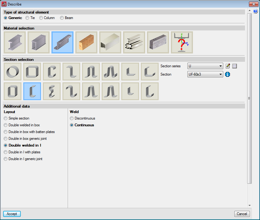
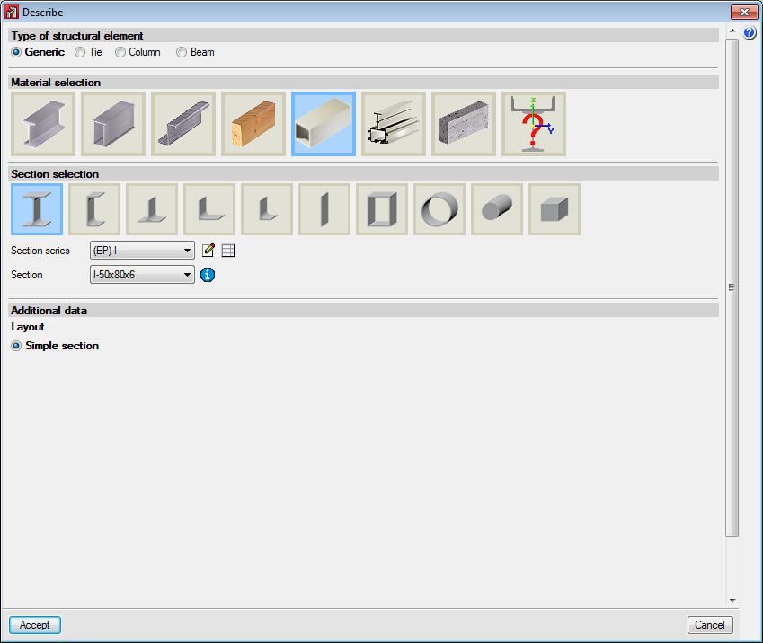
Aluminium section types
The Aluminium section button is available in the Describe dialogue box (Bar menu > Describe) that either allows a bar to be defined as an aluminium section from the library included in the program or defined geometrically.
The library contains a series of standard sections that can be configured and extended by the user. Both library and user-created sections can be:
- I-sections
- Channels
- Batten plates
- T-sections
- Symmetrical angle
- Angle
- Rectangular hollow section
- Circular hollow section
- Round bar
- Square bar
In the 2011.a version of the program, an extruded aluminium section editor was implemented, that is intended to facilitate the design and checking of aluminium alloy sections with special cross-sections.
In the 2012.a version, improvements regarding the automatic calculation of the susceptibility to local buckling due to compression and the design of special aluminium sections were also implemented.
For more information, please see the Special extruded aluminium sections webpage.
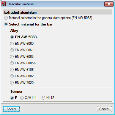
Aluminium alloys and tempers
In the Describe material dialogue box (Bar menu > Describe material) the alloy of the extruded aluminium for the selected aluminium sections is chosen, as well as its temper. The available alloys with their corresponding tempers are:
| Aluminium alloy | Temper |
| EN AW-5083 | F, H111 and H112 |
| EN AW-6060 | T5, T6, T64 and T66 |
| EN AW-6061 | T4 and T6 |
| EN AW-6063 | T5, T6 and T66 |
| EN AW-6005A | T6 |
| EN AW-6106 | T6 |
| EN AW-6082 | T4, T5 and T6 |
| EN AW-7020 | T6 |
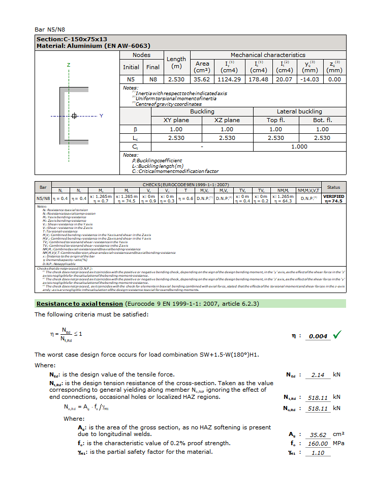
U.L.S check report on a steel bar
CYPE 3D generates detailed ultimate limit state check reports for aluminium bars with most of the codes implemented in the program.
More information can be found on the U.L.S check reports generated by CYPE programs can be found on the Detailed ultimate limit state check reports webpage. There is an example of a U.L.S check report of an aluminium bar in the U.L.S. check report of an aluminium bar. CYPE 3D. section.
Timber bars
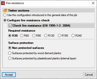
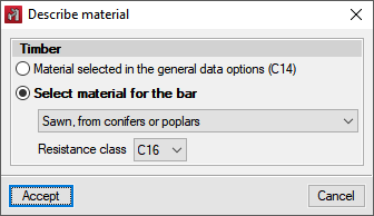
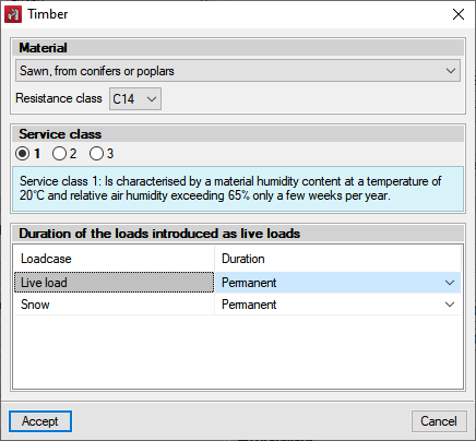
With the Timber sections module, CYPE 3D designs timber sections made of sawn wood (conifer and poplar species), sawn wood (frondescent species), homogenous glued laminated timber, and combined glued laminated timber sections. Rectangular sections, variable or constant sections, with constant or variable section, and circular sections. It includes a library of timber sections that users can configure and extend. The program also designs the timber sections under fire exposure so they comply with the selected code (CTE DB SE-M –Spain–, NBR 7190 or Eurocode 5) if users activate the fire resistance check of timber sections.
Concrete bars (defined as "Generic" type structural elements)
Rectangular or round concrete bars with constant depth can be entered in the program as well as rectangular concrete bars with variable depth. The program analyses the forces to which these bars are subjected and displays the results by simple loadcases, by combinations or by envelopes. Concrete bars are not checked for resistance i.e. their sections are neither checked nor designed. To check and design reinforced concrete bars in CYPE 3D, they must be defined as "Column" type or "Beam" type structural elements.
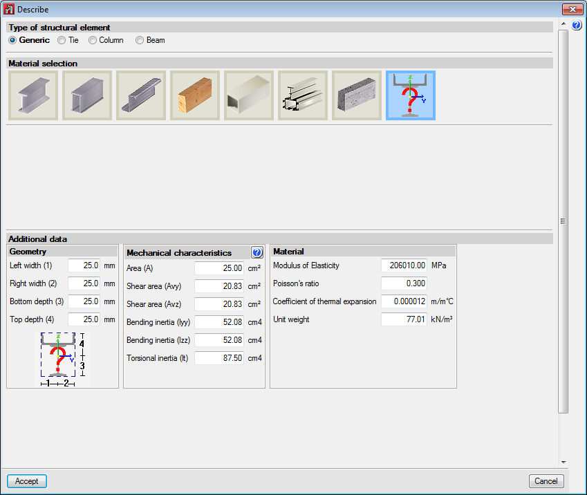
Bars made of other materials
CYPE 3D allows generic bars of any material to be defined. The program calculates the forces to which these bars are subjected, and displays the results by simple loadcase. The resistance of the generic bars is not checked, i.e. their sections are not checked or designed. Users define the following properties of the bars once they have been positioned in the structure:
- Geometry of the section
The distances between the centre of gravity and the outer perimeter of the section measured in the four directions of the two main local axes of the section must be entered:
- Left width
- Right width
- Bottom depth
- Top depth
- Mechanical properties
- Area
- Shear area Avy
- Shear area Avz
- Bending inertia Iyy
- Bending inertia Izz
- Torsional inertia It
- Top depth
- Material properties
- Modulus of Elasticity
- Poisson’s ratio
- Coefficient of thermal expansion
- Unit weight