CYPE 3D is an agile and efficient program designed for analysing three-dimensional structures of concrete, steel, composite concrete and steel, aluminium, timber or any other material bars; and of shells (flat two-dimensional elements of constant thickness whose perimeter is defined by a polygon). It includes the design of joints (welded and bolted joints rolled and welded steel I-sections and hollow sections) and their foundations with baseplates, footings and pile caps.
On this webpage, a detailed definition of bars as "Beam" type structural elements is provided.
For information on other properties in CYPE 3D, please visit the CYPE 3D webpage.
Bar structure types in CYPE 3D
CYPE 3D allows users to enter bars made of concrete, steel, composite steel and concrete, aluminium, timber or any other material.
The program designs the section and provides its optimum size for bars made of steel, aluminium, timber or concrete (if they have been defined as "Column" or "Beam" type structural elements).
Composite steel and concrete bars can be defined if they have been introduced as "Column" type structural elements and, even though they are not designed automatically, they are checked by the program with the properties that have been indicated by users.
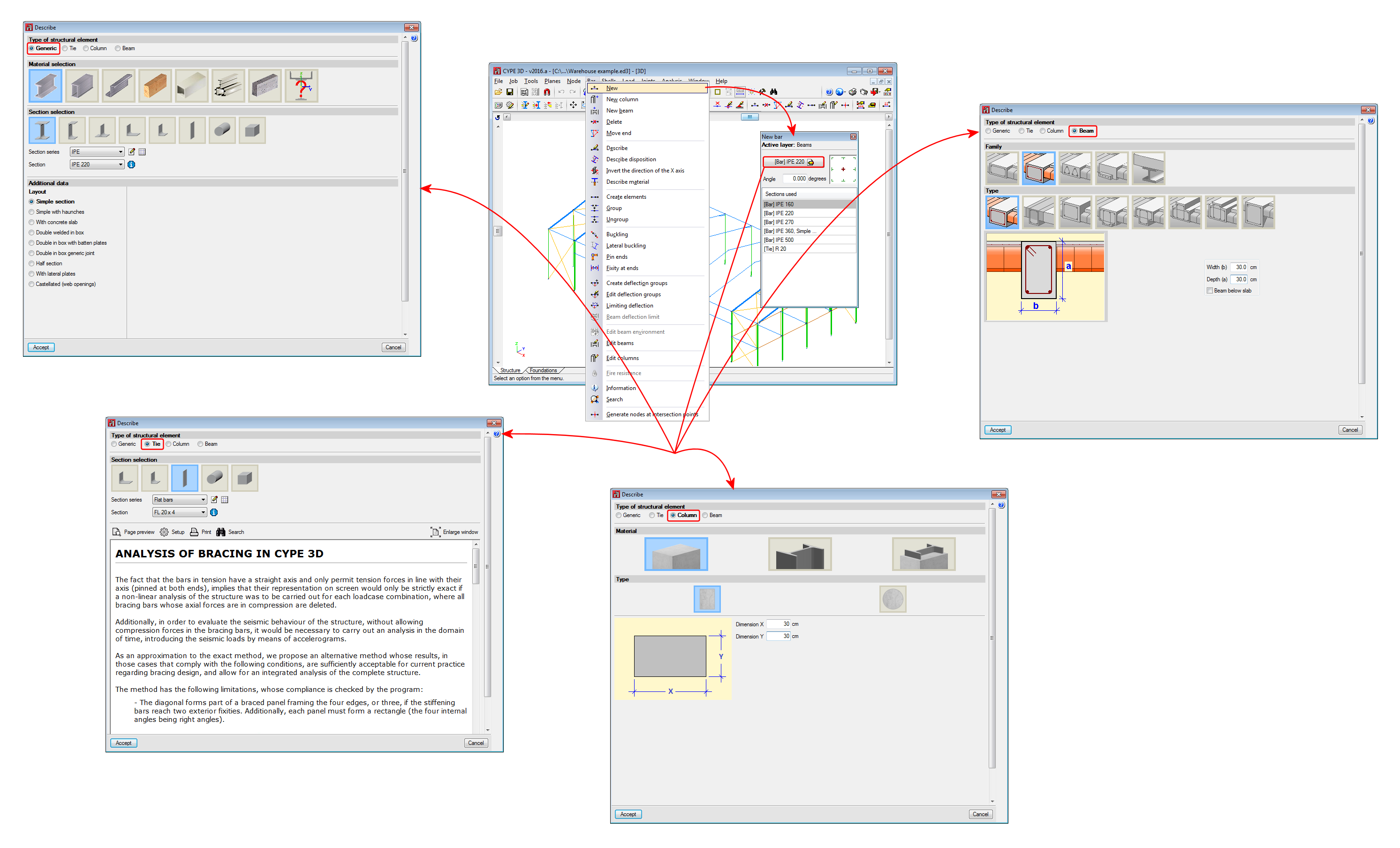
Introducing column and beam concepts in CYPE 3D means that the bars in the model are characterised as belonging to a type of structural element. In CYPE 3D, as of version 2016.a, bars are assigned to one of the following types of structural elements: "Generic" type structural elements, "Tie" type structural elements, "Column" type structural elements and "Beam" type structural elements.
This webpage discusses the definition of bars as "Beam" type structural elements. In order to consult the properties of bars defined as other types of structural elements, please consult the following links: "Generic" type structural elements, "Tie" type structural elements and "Column" type structural elements.
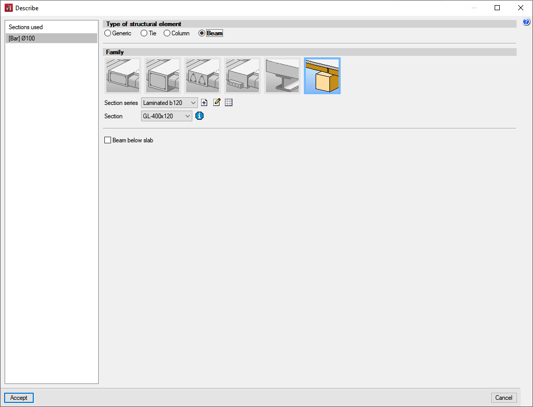
"Beam" type structural elements
In CYPE 3D, bars defined as "Beam" type structural elements require the definition of levels and grids. A "Beam" type structural element can be assigned the following materials: Reinforced concrete (rectangular, L-section, T-section, etc., lattice or prestressed beams), Steel (rolled, welded or cold-formed) and Timber (sawn or laminated).
- Rectangular, L-section, T-section, etc., lattice or prestressed concrete beams
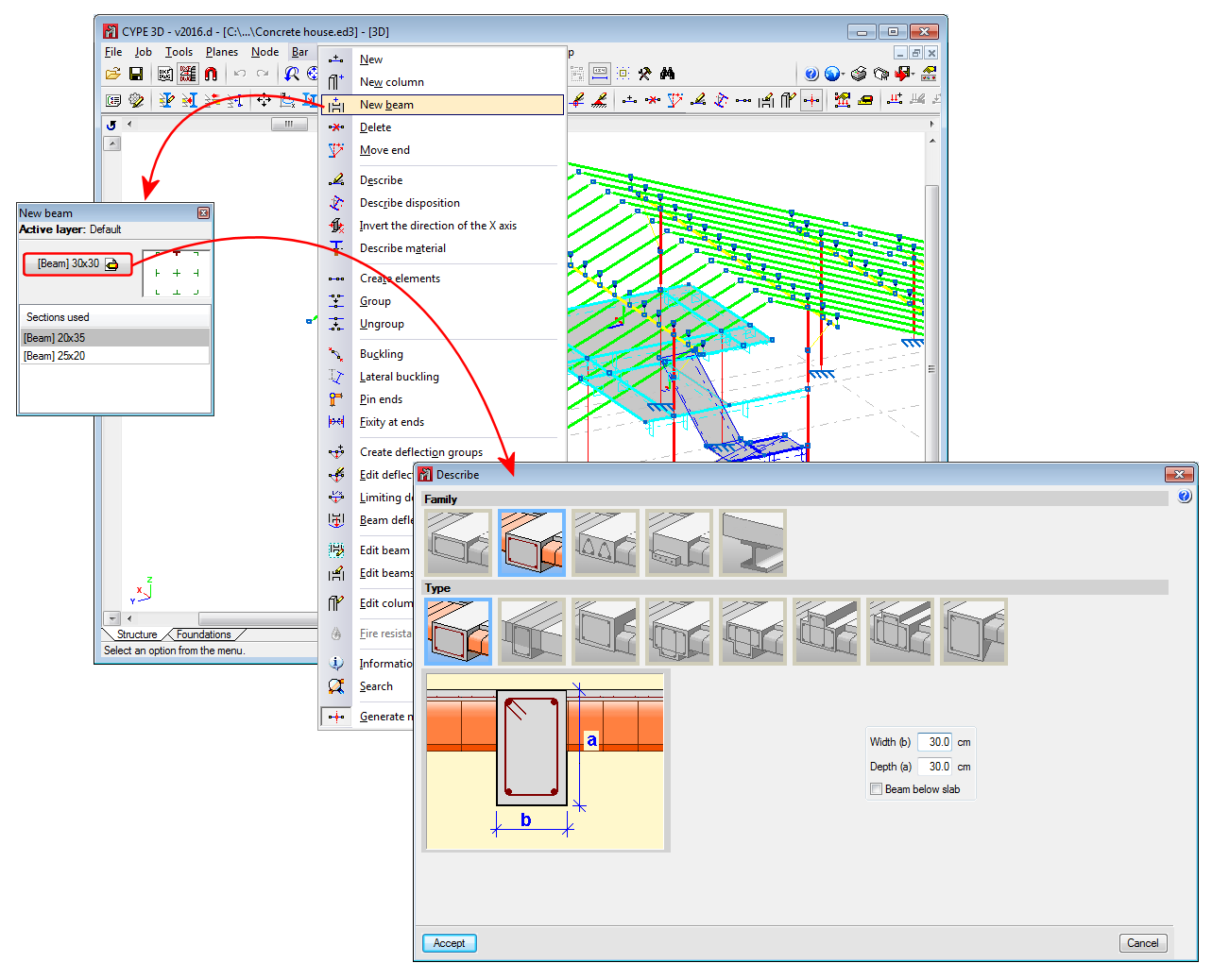
In order to define reinforced concrete beams as "Beam" type structural elements, the user license must include the "Concrete beams" module. More information on this module used by both CYPE 3D and CYPECAD, which allows both programs to design these structural elements, can be found on the Concrete beams webpage. - Steel sections
These can be rolled steel, cold-formed steel or welded steel sections and are designed in the same way as generic steel bars; although when they are defined as “Beam" type structural elements they are edited and modified using the “Advanced beam editor”. For CYPE 3D to be able to design beams with steel sections, the user license does not require any special permits; it only needs the “CYPE 3D” program. - Timber sections
These can be made up of rectangular sections of sawn or laminated timber. More information on this module used by both CYPE 3D and CYPECAD, which allows both programs to design these structural elements, can be found on the Timber sections page.
"Beam" type structural elements are designed, edited and checked using the Advanced column editor for the design codes implemented in the editor. Normally, codes that are repealed or out of use are those that are not available from this editor.
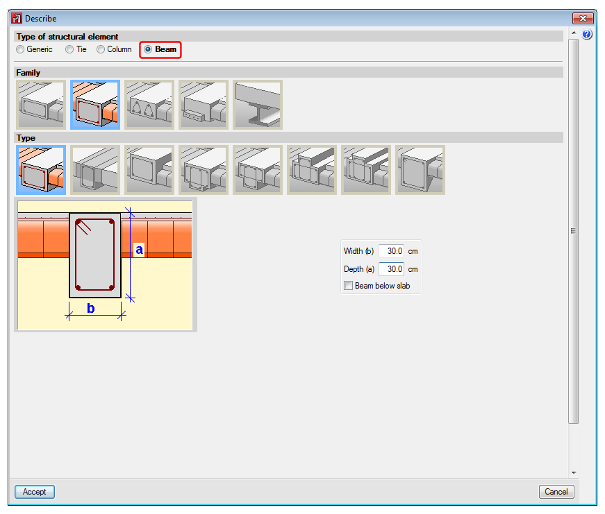
Properties of "Beam" type structural elements
A beam is an element that has been assigned the "Beam" type of structural element. A beam cannot be vertical, and furthermore, the angle between its XZ plane and the vertical plane containing it must be zero (i.e. it must not be rotated about the longitudinal axis of the beam). Beams can be grouped together to form continuous beams (beam alignments), under the following conditions:
- The end node of one is the starting node of the next.
- They are all the same type of material (concrete, rolled steel or cold-formed steel).
- If all are made of concrete, they must be of the same type of concrete.
Beams (and continuous beams) can be created in 3 ways:
- Introducing a bar using the “New bar” option and selecting a description with a "Beam" type structural element.
- Assigning the"Beam" type structural element to a previously introduced element.
- Using the “New beam” option in the Bar menu.
Regardless of how they are created, the program will manage the composition/decomposition of the previously introduced beams. The recommended option is number 3. The “New beam" option allows a continuous beam to be created in a simple way by introducing the elements of which it is comprised. To complete the introduction, by clicking on the right mouse button, CYPE 3D will create a continuous beam with all the introduced elements, where possible.
The element cannot be vertical, it does not need to belong to a level, but if they are defined, they shall be assigned to the nearest lower level. The element may be divided into bars, but if it is made of concrete, the reinforcement shall be continuous along its entire length.
If the continuous beam consists of more than one element, the deflection groups of the elements must be completely contained within the continuous beam. CYPE 3D will carry out the deflection analysis indicated in the design code for the beams of the continuous beam. No additional deflection limits need to be defined using the “Limiting deflection” option, although in this case, the program will carry out this check additionally.
The “Edit beams” option in the “Bar” menu contains the rest of the specific options for editing beams. This option shows a toolbar with the available options to speed up editing. The available options are:
- Create continuous beam
Creates a new continuous beam by selecting the beams that will make up the new continuous beam. - Edit nodes
Edits the geometry of a continuous beam node should it need to be different to the one established automatically. The geometry of the node affects the free span of the beams which is represented in the beam reinforcement editor, and therefore, the length of the placed reinforcement. - Edit adjacent floor slabs
Describes the floor slabs next to the bars making up the beams. With this option, the depth of flat beams can be defined and whether or not floor slabs are to be shown in the beam details drawing. Floor slabs are taken into account when checking the fire resistance of steel beams. - Edit reinforcement
Edits the beam reinforcement and opens the Advanced beam editor. - Assign reinforcement
Copies reinforcement from one beam to another. - Block reinforcement
Blocks the reinforcement of a beam to avoid it from being modified during the design process. - Unblock
Unblocks blocked reinforcement. - Edit beam or continuous beam references
Edit the beam references.
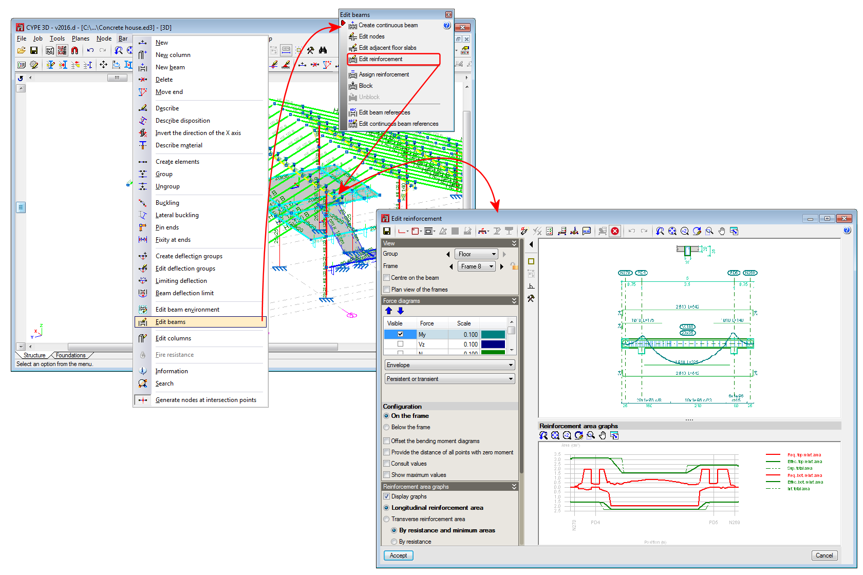
The beam reinforcement editing process implies that a solid model of the beam has been generated taking into account the node size from the elements of which it is composed. CYPE 3D automatically obtains the geometry of these nodes based on the geometry and position of the elements that do not belong to the beam. In any case, if the analysis is not satisfactory, users can define their own node geometry.
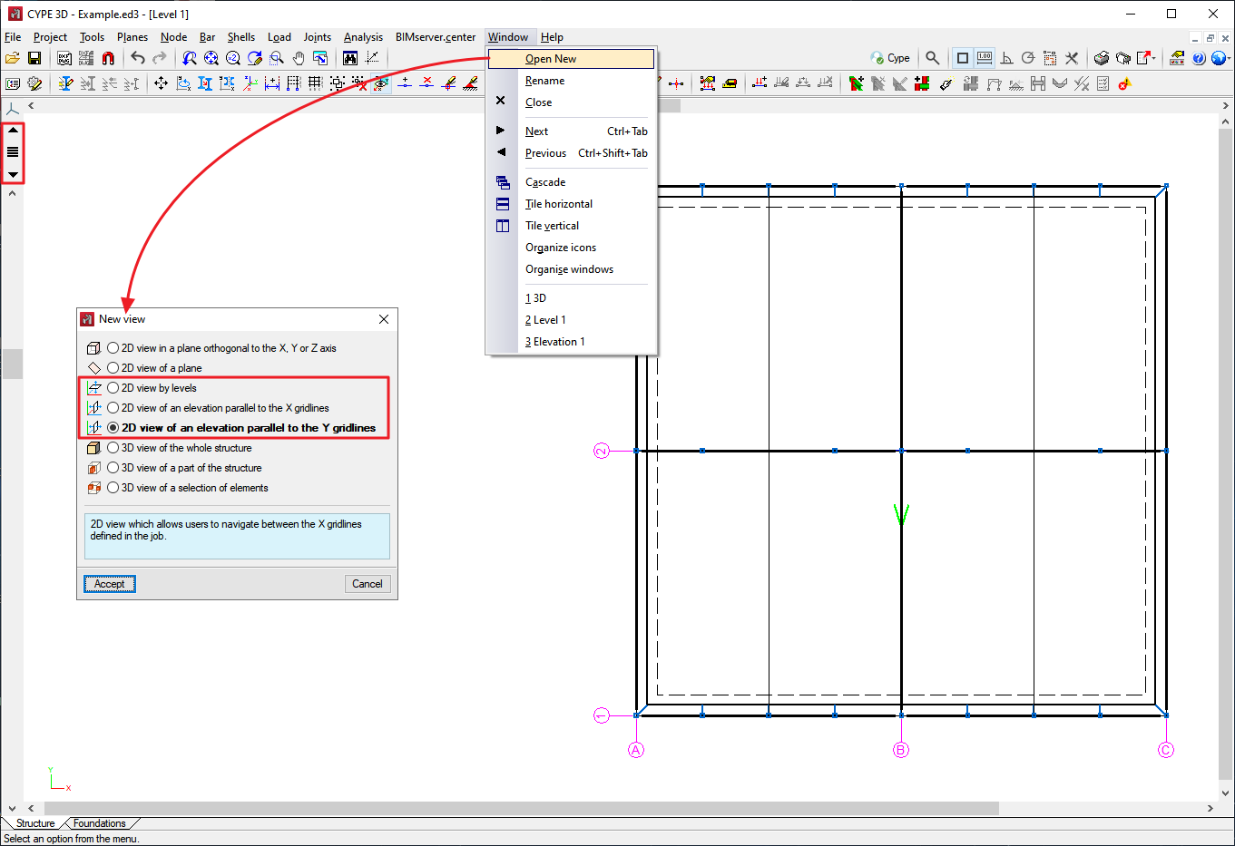
Levels, grids and views
The CYPE 3D "Planes" menu includes the Levels and Grids options. These options are essential for entering, checking and viewing works with "Column" and "Beam" type structural elements:
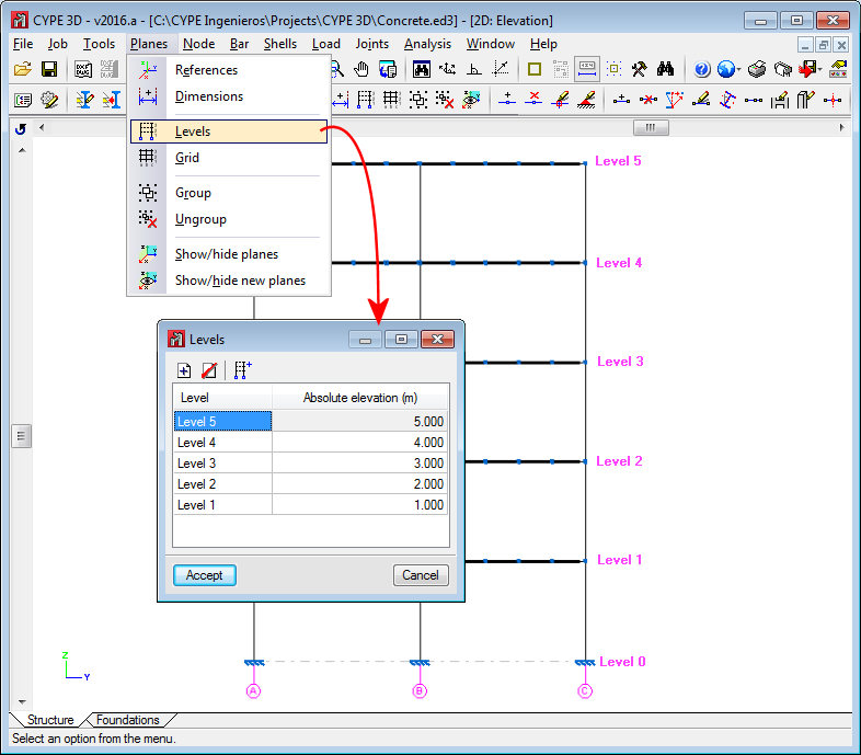
- Levels
Levels are horizontal planes parallel to the XY global plane, situated at a given global elevation that allow spatial sub-divisions specific to building structures to be introduced. Assigning elements to different levels is automatic. Elements situated between two levels are assigned to the closest lower level.
Levels are defined to both support the introduction of structural elements as well as to define views of a level (which help when working on structural elements). If columns are introduced, levels must be defined. Columns must begin and end at two different levels (although they start and end on a different level).
With this option, levels can be entered, edited or deleted. If the elevation of a level is modified, any elements contained in that level will be automatically moved to the new position.
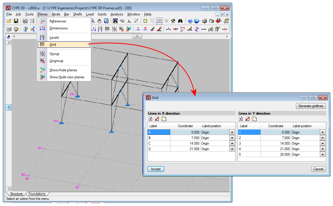
- Grids
A grid is a mesh composed of lines parallel to the global x and y axes. These lines define a spatial division of the structure in its elevation. A name can be assigned to each gridline and the position of the label can be controlled. Gridlines serve as both a support for the introduction of structural elements and for the definition of elevation views (which help when working on the structural elements).
This option allows grid lines to be entered, deleted or edited. Additionally, a rectangular grid generator has been implemented. If the position of a grid line is changed, all elements contained in the line are automatically moved to the new position.
By default, the grid will always be visible on-screen, unless it is deactivated using the “Planes > References” option. The grid can also be displayed on drawings.
- Views by levels and views of elevations
If levels and grids have been defined, the program will allow views for levels and elevations to be created. Once the views have been defined, it is possible to move from one level to the next, or from one elevation to the next, using the buttons (up, down, and select levels or elevations).
Both level views and elevation views are 2D views. Therefore, any element entered in a view will be contained in that plane view. In the case of level views, the program displays elements belonging to the level and those reaching or beginning from it. The program allows for the views to be rotated in both cases, so users can better adjust their view of the elements.


 buttons (up, down, and select levels or elevations).