


Concrete beams
Using the "Concrete beams" module, users can enter and design the following types of concrete beams:
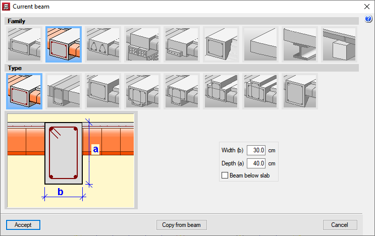
- Rectangular section beams
Flat, dropped (downward drop or inverted), or dropped with a collaborating compression head. - Variable section dropped rectangular beams (depending on the selected code).
- ‘L’ or ‘T’ beams
Flat and dropped (downward drop or inverted with a collaborating compression head with greater or equal depth than the slab). - Precast lattice beams
Flat beams with rectangular, ‘L’ or ‘T’ transverse sections, and dropped beams with rectangular transverse sections. - Prestressed beams
Flat and dropped beams with rectangular, ‘L’ or ‘T’ transverse sections. - Beams with external fixity (infinitely rigid beams)
Beams with free displacement and free rotation, with fixed displacement and free rotation, and with fixed displacement and rotation. - Non-structural or limit beams (non-rigid beams).
Data entry
CYPECAD also designs steel, composite beams (with shear studs) and foundation beams, although the Steel beams module and Floating columns would be required, respectively.
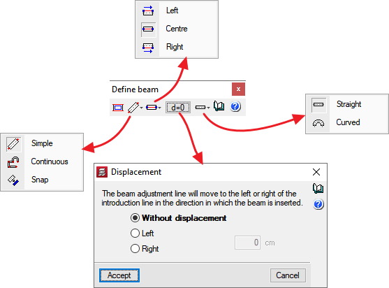
Beams can have a straight or curved axis and the program allows for both of them to be entered in ‘Continuous mode’ (the final point of the beam that is marked is the initial point of the next) or in ‘Simple mode’ (once the final point of the beam is marked, if another beam is to be entered, the initial point of the next beam has to be marked).
The faces or axes of the beams can be adjusted to a reference point (column axes, beam ends or snaps to elements of a drawing file with DXF or DWG format). The selected adjustment (faces or axis of the beam to be entered) can be displaced with respect to the reference points.
CYPECAD can also automatically assign a beam outline to a polygon (open or closed) in a DXF or DWG drawing. The faces or axis of the beam can be adjusted to the polygon, and even apply a specific displacement. Another feature of CYPECAD is the automatic entry of the beams of the floor slabs following the instructions of the users and the outlines of the floor displayed in the DXF or DWG drawing template. Both these tools belong to the Automatic entry module.
The program contains tools that allow for the interaction of the beams with the rest of the structure to be defined. Users can pin beams at either end, modify the fixity coefficient of the faces of the beams, assign minimum moments, manage the beam alignments that are generated (consecutive spans, which the program considers to be a single frame), divide or join alignments, and enter a beam that is shared between two floors.
Results analysis
Beam editors in CYPECAD
CYPECAD has two beam editors: the beam editor for earlier versions than the 2013.e version and the Advanced beam editor, which was implemented in the 2013.e version.
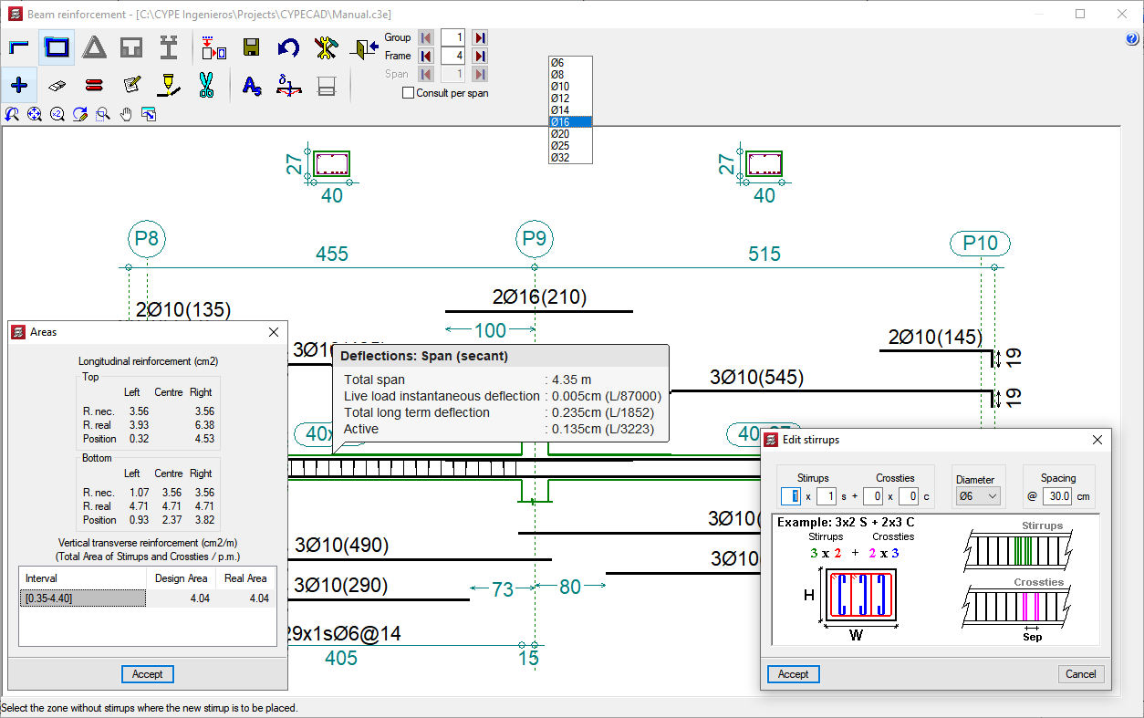
The beam editor, which is available for versions earlier than the 2013.e version, allows for the reinforcement to be modified graphically. Reinforcement bars, anchorages and stirrups can be added, deleted, matched, divided and modified. The real and required reinforcement areas of each span of the frame can also be consulted.
The Advanced beam editor contains more features for users to analyse the design carried out by CYPECAD.
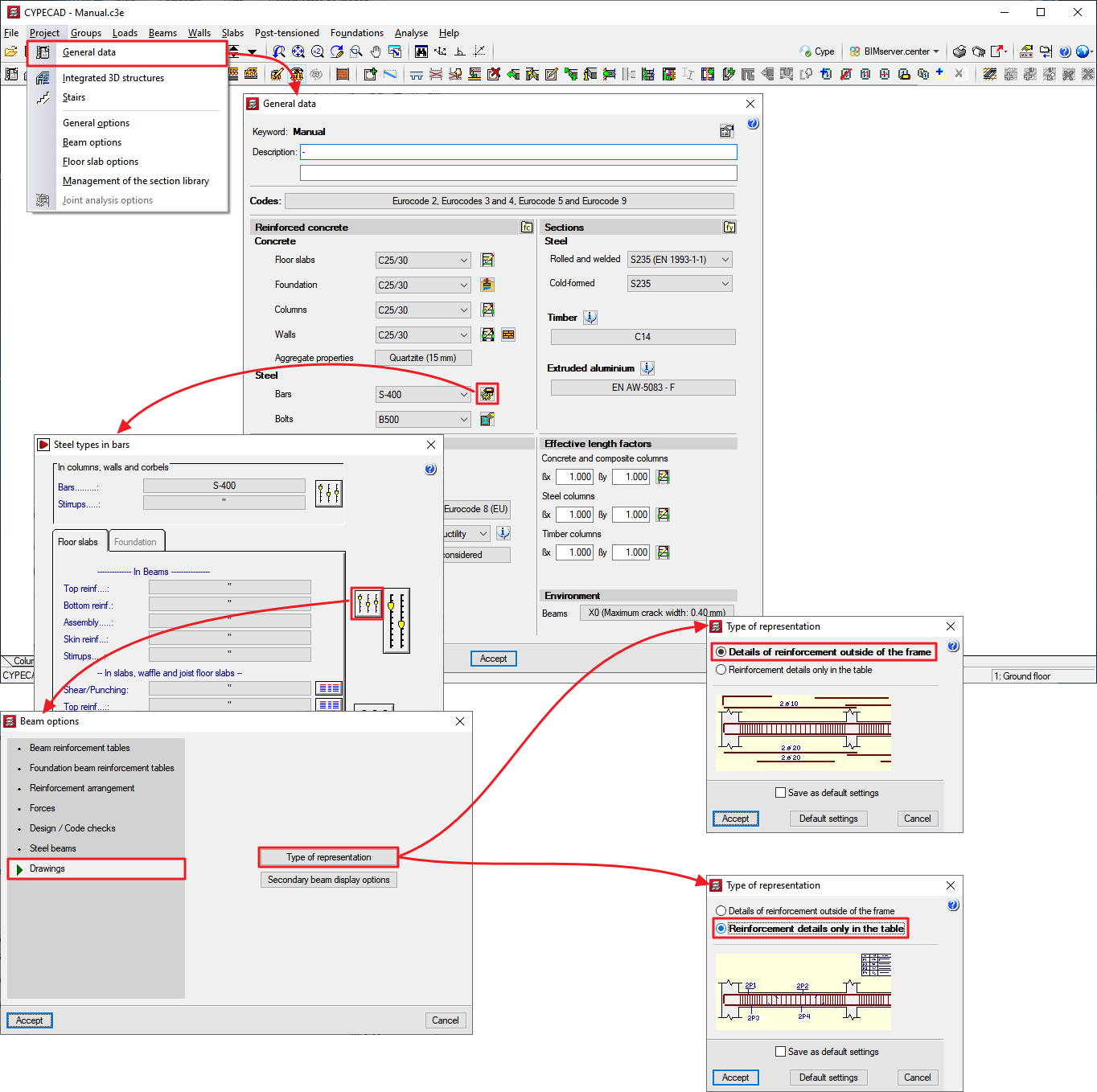
The choice of which editor to use depends on the concrete and seismic design codes selected for the design of the structure (Project > General data). More information on the codes for which the Advanced beam editor is available can be consulted in the section: Design codes available for use with the Advanced beam editor, of this webpage. More design codes are added to the current list with each program version.
Advanced beam editor
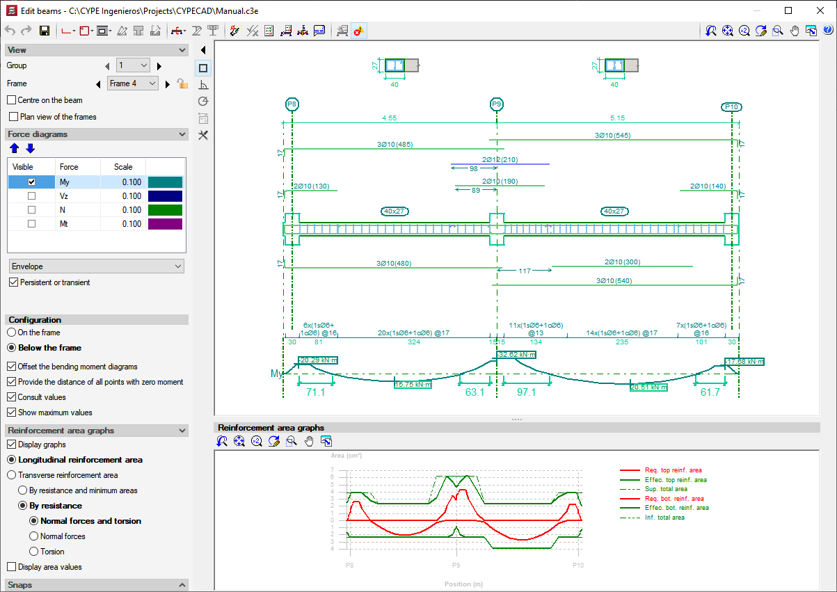
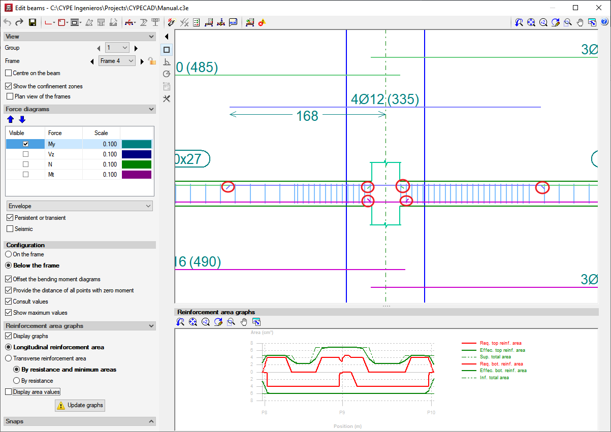
The Advanced beam editor provides users with a very effective tool to revise and modify the design of concrete and steel beams. It allows users to consult a wide range of information on the selected frame, which is automatically updated when any changes are carried out (Results > Beams/Walls > Edit beams). It consists of the same beam editor used in Continuous beams. It provides a quick and comfortable graphical edition interface for the resistant elements of the frame (reinforcement bars, steel sections, lattices, shear studs, etc). It also provides:
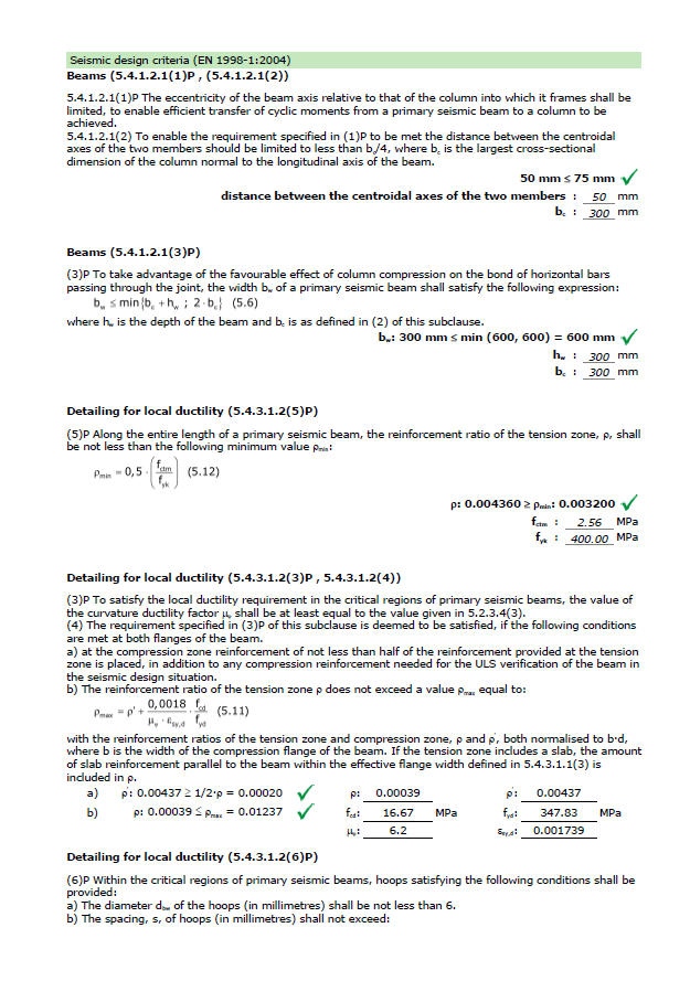
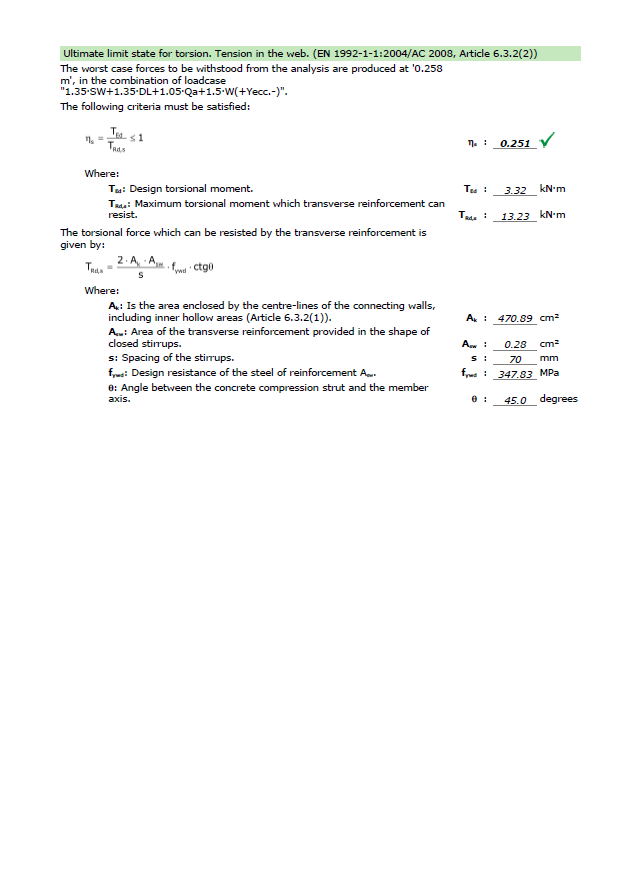
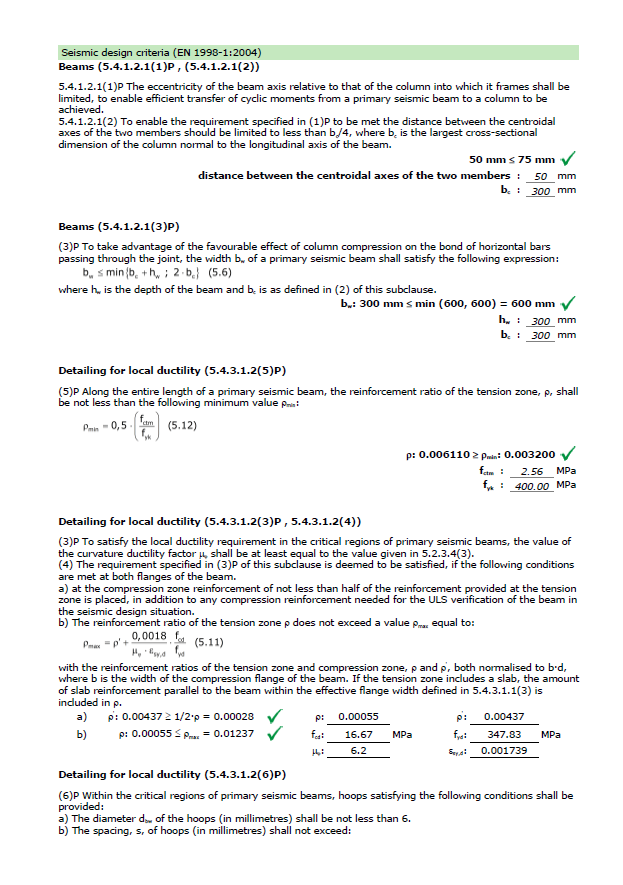
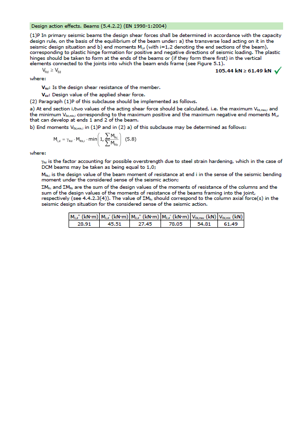
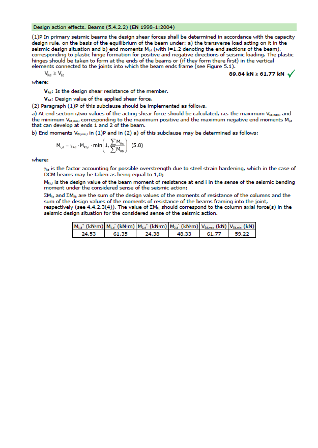
- Detailed U.L.S. and S.L.S. check reports for concrete beams (with check for failure due to torsion and design criteria for seismic loads)
- U.L.S. and S.L.S. reports for steel beams
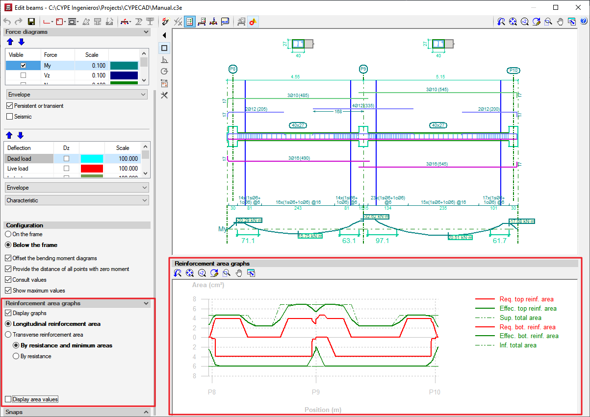
- Required and effective reinforcement area diagrams
- Bar bending diagrams and reinforcement configuration option on the frame drawings
- Horizontal and vertical openings in concrete beams
- Variable section dropped rectangular beams
- Other options of the Advanced beam editor
More information on the codes for which the Advanced beam editor is available can be consulted in the section: Design codes available for use with the Advanced beam editor, on this webpage.
Detailed U.L.S. and S.L.S. check reports for concrete beams (with check for failure due to torsion and design criteria for seismic loads)
CYPECAD generates Detailed Ultimate and Serviceability (U.L.S. and S.L.S.) Limit State check reports for concrete beams using the Advanced beam editor (![]() and
and ![]() buttons of the editor). In the generated U.L.S. and S.L.S. reports, reference is made to the articles of the codes in which these checks are defined.
buttons of the editor). In the generated U.L.S. and S.L.S. reports, reference is made to the articles of the codes in which these checks are defined.
More features of the beam editor are present in CYPECAD than in Continuous beams due to the torsional and seismic analysis performed by CYPECAD. The U.L.S. and S.L.S. reports provided in CYPECAD include checks for failure due to torsion in reinforced concrete beams and also incorporate the specific checks of the design criteria for seismic loads for reinforced concrete beams (including the shear capacity design criteria).


U.L.S and S.L.S. reports for steel beams
The detailed U.L.S. and S.L.S. check reports for steel beams (![]() and
and ![]() buttons of the editor) and the steel beam series check
buttons of the editor) and the steel beam series check ![]() button of the editor) are also obtained in the new beam editor. For projects where the Advanced beam editor is not available (depending on the selected design code), the detailed U.L.S. and S.L.S. check reports are obtained using the Beam errors option in the Beams/Walls option in the Results tab.
button of the editor) are also obtained in the new beam editor. For projects where the Advanced beam editor is not available (depending on the selected design code), the detailed U.L.S. and S.L.S. check reports are obtained using the Beam errors option in the Beams/Walls option in the Results tab.
Required and effective reinforcement area diagrams
CYPECAD’s Advanced beam editor includes diagrams indicating the required and effective areas of the reinforcement provided in the edited frame.
Bar bending schedule and reinforcement configuration of the reinforcement details in the frame drawings
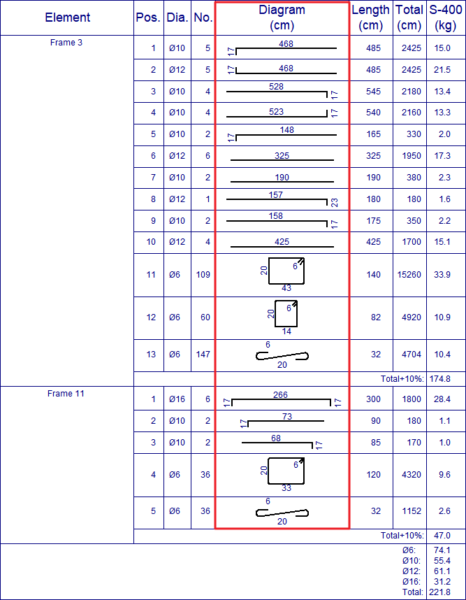
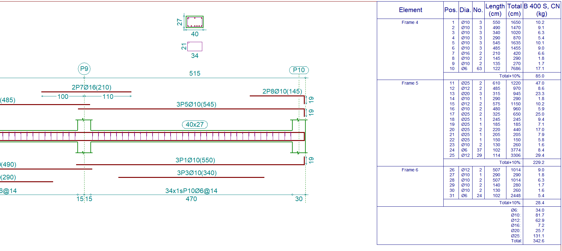
The frame drawings include, within the reinforcement details, the bar bending schedule for the longitudinal and transverse reinforcement of the frame (File menu > Print > Project drawings > select Frames drawing as the type of drawing > activate Reinforcement layout in the drawing to be generated).
The bar bending schedule is also included in the Column detailing drawings (File > Print > Project drawings) and in the reinforcement of the Punching shear verification program.
The reinforcement details to be displayed in the drawings can be configured using the Advanced beam editor. There are two options:
- Details of reinforcement outside of the frame
The reinforcement details are drawn outside the longitudinal section of each frame. - Reinforcement details only in the table
The reinforcement details are not drawn in the frame and are only displayed in the reinforcement schedule or details table.
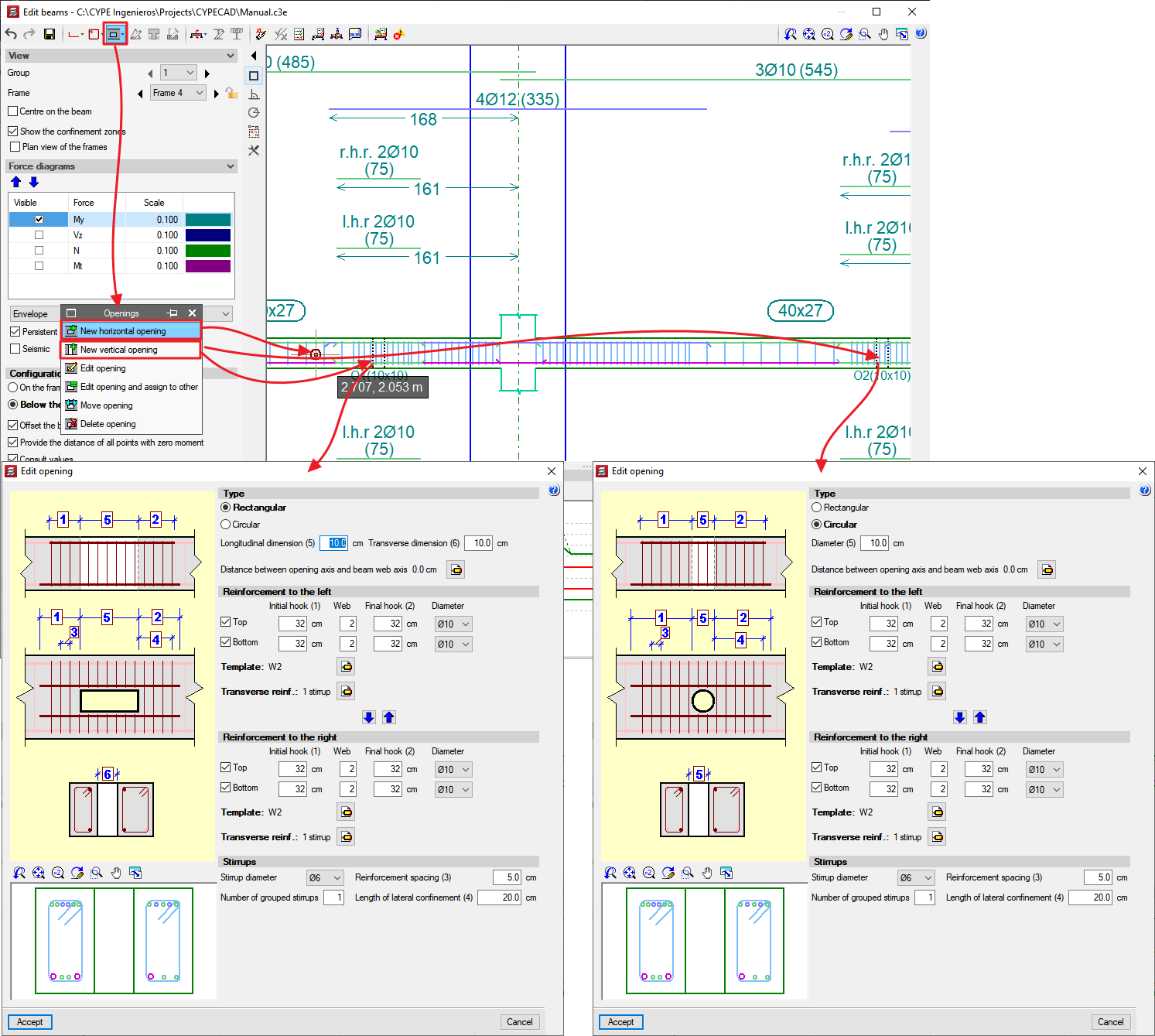
Horizontal and vertical openings in concrete beams
CYPECAD’s Advanced beam editor and Continuous beams allow users to enter horizontal or vertical openings (rectangular or circular) in reinforced concrete beams.
Variable section dropped rectangular beams
The possibility of entering variable section dropped rectangular beams has been implemented in those projects using concrete and seismic codes (in the case of seismic analysis), for which the advanced beam editor has been implemented.
This possibility already existed in the Continuous beams program. Now, in CYPECAD, there is a new type of beam in the beam definition dialogue box where the program asks for the width, the initial depth and the final depth.
Other options of the Advanced beam editor
The Advanced beam editor contains more tools and options for editing the reinforcement. Below is a sample of these tools:
- Join additional, assembly or skin reinforcement
Activated using the button from the top toolbar of the beam editor.
Regarding the additional reinforcement bars, the program allows for reinforcement of the same diameter to be joined without substituting the reinforcement of one span for that of the other. When joining the assembly or skin reinforcement, the program substitutes the reinforcement selected in second place will be substituted by those that were selected first (regardless of the number of bars and diameter). - Block or unblock the reinforcement of the frame
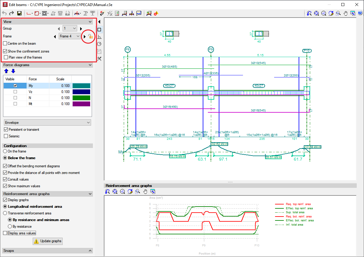
This option is represented by an icon situated in the View section of the lateral menu of the new beam editor. This icon can be represented in two ways: an open padlock or a closed padlock. The open padlock indicates the reinforcement of the frame being edited is not blocked, and the closed padlock indicates it is blocked. By clicking on the icon, the blocked status of the beam reinforcement changes. Blocking of the reinforcement is only effective for actions carried out outside the editor. In other words, if the frame's reinforcement is blocked, CYPECAD will not be able to modify it with any of the reinforcement options or even by analysing the job (Beam Definition tab > Analyse). Nonetheless, even if the reinforcement of the frame is blocked, it can be modified in the Beam editor (changing it manually or using the Redesign button, as described in the following point). - Redesign the frame reinforcement
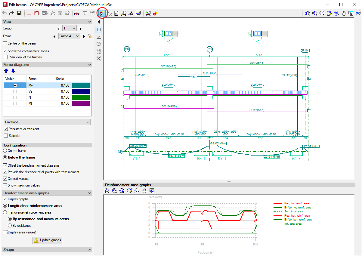
The Redesign frame option is represented by the button, located in the top toolbar of the beam editor. This option redesigns the frame with the forces calculated by CYPECAD, even if the option to block the reinforcement of the frame is activated in the editor. - Curve representation for bent bars
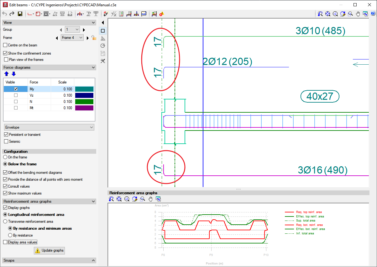
The reinforcement anchorage curves are represented in the beam editor and in the reinforcement drawings, in accordance with the selected code. - Marks at bar ends, which are anchored without any bends
The program marks (using inclined lines) bars that are anchored without any bends. These marks are only provided if the ends of the bars are drawn overlapping other bars (due to them being in the same horizontal plane). This way, users can identify where the bar begins and ends within the longitudinal section of the frame. These marks are visible within the on-screen display of the longitudinal section of the frame and on reinforcement details drawings.

Design codes available for use with the Advanced beam editor
CYPECAD’s Advanced beam editor is available for the following concrete design codes:
- ABNT NBR 6118:2007 (Brazil)
Norma Brasileira ABNT NBR 6118 (2007). Projeto de estruturas de concreto - Procedimento. - ACI 318M-08 (USA)
Building Code Requirements for Structural Concrete (ACI 318M-08). - BAEL 91 (R-99) (France)
Règles techniques de conception et de calcul des ouvrages et constructions en béton armé suivant la méthode des états limites. - CIRSOC 201-2005 (Argentina)
Reglamento Argentino de Estructuras de Hormigón. - EHE-08 (Spain)
Instrucción de hormigón estructural. - Eurocode 2 (EU)
Proyecto de estructuras de hormigón. EN 1992-1-1:2004/AC 2008 - Eurocode 2 (France)
Calcul des structures en béton. NF EN 1992-1-1 :2005/NA: Mars 2007 - Eurocode 2 (Portugal)
Projecto de estruturas de betão. NP EN 1992-1-1:2010/NA - Eurocode 2 (Romania)
Eurocode 2: Design of concrete structures. SR EN 1992-1-1:2004/AC - IS 456: 2000 (India)
Indian Standard. Plain and reinforced concrete code of practice (Fourth Revision). - NCh 430.Of2008 (Chile)
Norma Chilena oficial NCh430.Of2008 (Basada en ACI 318-05). - NSR-10 (Colombia)
Reglamento Colombiano de Construcción Sismo Resistente NSR-10. Título C Concreto estructural. - NTCRC:2004 (Mexico)
Normas técnicas complementarias del reglamento de construcciones para el Distrito Federal. - NTE E.060: 2009 (Peru)
Reglamento nacional de edificaciones. Norma E.060 Concreto Armado. - SP 63.13330.2012 (Russian Federation)
Concrete and reinforced concrete. Construction. Updated edition SNIP 52-01-2003. Moscow 2012
If users carry out a seismic analysis of the structure, the Advanced beam editor will be available if the concrete code and seismic code are compatible. For each indicated concrete code, the compatible seismic codes are as follows:
- ABNT NBR 6118:2007 (Brazil)
- ABNT NBR 15421:2006 (Brazil)
Projeto de estruturas resistentes a sismos - Procedimento. - 1997 UBC (USA)
Uniform Building Code. - 2009 IBC (USA)
International Building Code.
- ABNT NBR 15421:2006 (Brazil)
- ACI 318M-08 (USA)
- 1997 UBC (USA)
Uniform Building Code. - 2009 IBC (USA)
International Building Code. - 2011 PRBC (Puerto Rico)
Puerto Rico Building Code. - ASCE 7-05 (USA)
Minimum Design Loads for Buildings and Other Structures. - NBDS-2006 (Bolivia)
Norma Boliviana de Diseño Sísmico (2006). Título A. Análisis y diseño sismo resistente. - CFE93 (Mexico)
Manual de Diseño de Obras Civiles. Diseño por Sismo. - CFE 2008 (Mexico)
Manual de Diseño de Obras Civiles. Diseño por Sismo. Comisión Federal de Electricidad. México 2008. - CPE INEN 5:2001 (Ecuador)
Código Ecuatoriano de la Construcción. Requisitos Generales de Diseño: Peligro Sísmico, Espectros de Diseño y Requisitos Mínimos de Cálculos para Diseño Sismo-Resistente. - CSCR-2010 (Costa Rica)
Código Sísmico de Costa Rica 2010. - NC 46:1999 (Cuba)
Construcciones sismo resistentes. Requisitos básicos para el diseño y construcción. - NEC -11 (Ecuador)
Norma Ecuatoriana de la Construcción. Capítulo 2.- Peligro sísmico y requisitos de diseño. - NSE-10 (Guatemala)
Normas de Seguridad Estructural de Edificaciones y Obras de Infraestructura para la República de Guatemala, edición 2010. - NSR-10 (Colombia)
Reglamento Colombiano de Construcción Sismo Resistente (2010). - CHOC-04 (Honduras)
Código Hondureño de la Construcción. Normas Técnicas Complementarias. XII. Cargas y Fuerzas Estructurales. Diseño por Sismo. - REP-04 (Panama)
Reglamento para el Diseño Estructural en la República de Panamá 2004 (REP-04). - R-001 2011 (Dominican Republic)
Reglamento para el Análisis y Diseño Sísmico de Estructuras. - COVENIN 1756-1:2001 (Venezuela)
Norma Venezolana COVENIN 1756-1:2001. Edificaciones sismorresistentes. - IS 1893:2002 (India)
Criteria for earthquake-resistant design of structures. Part 1 General Provisions and Buildings (Section 7.5). - IS 13920:1993 (India)
Ductile detailing of reinforced concrete structures subjected to seismic forces - Code of practice.
- 1997 UBC (USA)
- BAEL 91 (R-99) (France)
- PS 92 (France)
Règles de Construction Parasismique - Règles PS applicables aux bâtiments – PS 92. - PS 92 (version révisée 2010) (France)
Règles de Construction Parasismique - Règles PS applicables aux bâtiments – PS 92 (version révisée 2010). - RPA 99/v 2003 (Algeria)
Règles Parasismiques Algériennes RPA 99 / VERSION 2003. - RPS 2000 (Morocco)
Règlement de Construction Parasismique.
- RPS 2011 (Morocco)
Règlement de Construction Parasismique (version révisée 2011). - 1997 UBC (USA)
Uniform Building Code. - 2009 IBC (USA)
International Building Code.
- PS 92 (France)
- CIRSOC 201-2005 (Argentina)
- CIRSOC 103-2008 (Argentina)
Normas Argentinas para Construcción Sismorresistente - Proyecto de Reglamento CIRSOC 103, Parte I: Construcciones en general. Se utilizan los criterios de armado por ductilidad y criterios de diseño sísmico por capacidad del reglamento CIRSOC 103-2005 (Normas Argentinas para Construcción Sismorresistente. Parte II: Construcciones de Hormigón Armado). - CIRSOC 103-1991 (Argentina)
Normas Argentinas para Construcción Sismorresistente. Reglamento CIRSOC 103 Parte I: Construcciones en general. Se utilizan los criterios de armado por ductilidad y criterios de diseño sísmico por capacidad del reglamento CIRSOC 103-2005 (Normas Argentinas para Construcción Sismorresistente. Parte II: Construcciones de Hormigón Armado). - 1997 UBC (USA)
Uniform Building Code. - 2009 IBC (USA)
International Building Code.
- CIRSOC 103-2008 (Argentina)
- EHE-08 (Spain)
- NCSE-02 (Spain)
Norma de Construcción Sismorresistente. Parte general y Edificación. - 1997 UBC (USA)
Uniform Building Code. - 2009 IBC (USA)
International Building Code.
- NCSE-02 (Spain)
- Eurocode 2 (EU)
- Eurocode 8 (EU)
EN 1998-1. Eurocódigo 8: Proyecto de estructuras sismorresistentes Parte 1: Reglas generales, acciones sísmicas y reglas para edificios. - Eurocode 8 (France)
NF EN 1998-1/NA (2007) Eurocode 8: Calcul des structures pour leur résistance aux séismes Partie 1 : Règles générales, actions sismiques et règles pour les bâtiments Annexe nationale à la NF EN 1998-1:2005.1. - Eurocode 8 (Portugal)
NP EN 1998-1 (2010). Eurocódigo 8 - Projecto de estruturas para resistência aos sismos
Parte 1: Regras gerais, acções sísmicas e regras para edifícios. - Eurocode 8 (Belgium)
NBN-ENV 1998-1-1: 2002 NAD-E/N/F Eurocode 8: Conception et dimensionnement des structures pour la résistance au séisme. Partie 1-1 : Règles générales. Actions sismiques et exigences générales pour les structures. - PS 92 (France)
Règles de Construction Parasismique - Règles PS applicables aux bâtiments – PS 92. - PS 92 (version révisée 2010) (France)
Règles de Construction Parasismique - Règles PS applicables aux bâtiments – PS 92 (version révisée 2010). - RPA 99/v 2003 (Algeria)
Règles Parasismiques Algériennes RPA 99 / VERSION 2003. - RPS 2000 (Morocco)
Règlement de Construction Parasismique. - RPS 2011 (Morocco)
Règlement de Construction Parasismique (version révisée 2011). - 1997 UBC (USA)
Uniform Building Code. - 2009 IBC (USA)
International Building Code.
- Eurocode 8 (EU)
- Eurocode 2 (France)
- Eurocode 8 (France)
NF EN 1998-1/NA (2007) Eurocode 8 : Calcul des structures pour leur résistance aux séismes Partie 1 : Règles générales, actions sismiques et règles pour les bâtiments Annexe nationale à la NF EN 1998-1:2005.1. - PS 92 (France)
Règles de Construction Parasismique - Règles PS applicables aux bâtiments – PS 92. - PS 92 (version révisée 2010) (France)
Règles de Construction Parasismique - Règles PS applicables aux bâtiments – PS 92 (version révisée 2010). - RPA 99/v 2003 (Algeria)
Règles Parasismiques Algériennes RPA 99 / VERSION 2003. - RPS 2000 (Morocco)
Règlement de Construction Parasismique. - RPS 2011 (Morocco)
Règlement de Construction Parasismique (version révisée 2011). - 1997 UBC (USA)
Uniform Building Code. - 2009 IBC (USA)
International Building Code.
- Eurocode 8 (France)
- Eurocode 2 (Portugal)
- Eurocode 8 (Portugal)
NP EN 1998-1 (2010). Eurocódigo 8 - Projecto de estruturas para resistência aos sismos
Parte 1: Regras gerais, acções sísmicas e regras para edifícios. - 1997 UBC (USA)
Uniform Building Code. - 2009 IBC (USA)
International Building Code.
- Eurocode 8 (Portugal)
- Eurocode 2 (Romania)
- Eurocode 8 (UE)
EN 1998-1. Eurocódigo 8: Proyecto de estructuras sismorresistentes Parte 1: Reglas generales, acciones sísmicas y reglas para edificios. - 1997 UBC (USA)
Uniform Building Code - 2009 IBC (USA)
International Building Code.
Esta norma sísmica no dispone de criterios de diseño por capacidad.
- Eurocode 8 (UE)
- IS 456: 2000 (India)
- IS 1893:2002 (India)
Criteria for earthquake-resistant design of structures. Part 1 General Provisions and Buildings (Section 7.5). - IS 13920:1993 (India)
Ductile detailing of reinforced concrete structures subjected to seismic forces - Code of practice. - 1997 UBC (USA)
Uniform Building Code. - 2009 IBC (USA)
International Building Code.
- IS 1893:2002 (India)
- NCh 430.Of2008 (Chile)
- 433.Of1996 (Chile)
Norma Chilena Oficial. Diseño Sísmico de Edificios. - CSCR-2010 (Costa Rica)
Código Sísmico de Costa Rica 2010. - 1997 UBC (USA)
Uniform Building Code. - 2009 IBC (USA)
International Building Code.
- 433.Of1996 (Chile)
- NSR-10 (Colombia - Título C Concreto estructural)
- NSR-10 (Colombia)
Reglamento Colombiano de Construcción Sismo Resistente (2010). - 1997 UBC (USA)
Uniform Building Code. - 2009 IBC (USA)
International Building Code.
- NSR-10 (Colombia)
- NTCRC:2004 (Mexico)
- CFE 2008 (Mexico)
Manual de Diseño de Obras Civiles. Diseño por Sismo - NTC - 2004 (Mexico)
Normas Técnicas Complementarias para Diseño por Sismo
- CFE 2008 (Mexico)
- NTE E.060: 2009 (Peru)
- Norma Técnica E.030 (Peru)
Norma Técnica E.030 Diseño Sismorresistente. - 1997 UBC (USA)
Uniform Building Code. - 2009 IBC (USA)
International Building Code.
- Norma Técnica E.030 (Peru)
- SP 63.13330.2012 (Russian Federation)
- СНиП II-7-81* (Russian Federation)
СТРОИТЕЛЬСТВО В СЕЙСМИЧЕСКИХ РАЙОНАХ. Актуализированная редакция
Construction in seismic regions. Updated edition.
- СНиП II-7-81* (Russian Federation)
More concrete codes and their corresponding compatible seismic codes will be implemented in upcoming versions of the Advanced beam editor of CYPECAD.
More results analysis options
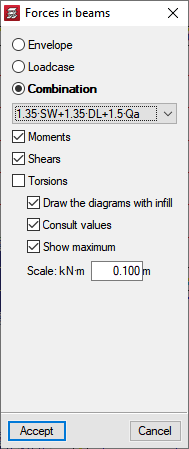
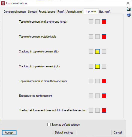
CYPECAD has results analysis tools available, such as the graphical representation, with numerical values, of the force envelopes (moments, shears and torsional forces), of the simple loadcase forces and loadcase combination forces.


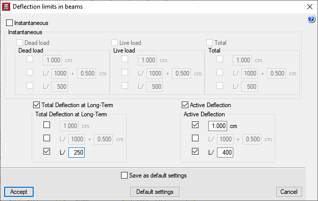
The program also calculates the deflection of the beams (instantaneous deflection, long term deflection and active deflection) and warns users if any beams exceed the limits established in the program, in accordance with the selected code. These deflection limits can be modified by users.
Reinforcement can be copied from one frame to another of the same or different floors, and group frames within the same floor, before and after the analysis.
Users can also lock the frame reinforcement they select so as not to lose manual modifications of their reinforcement, even if the project is reanalysed after making minor changes to it.
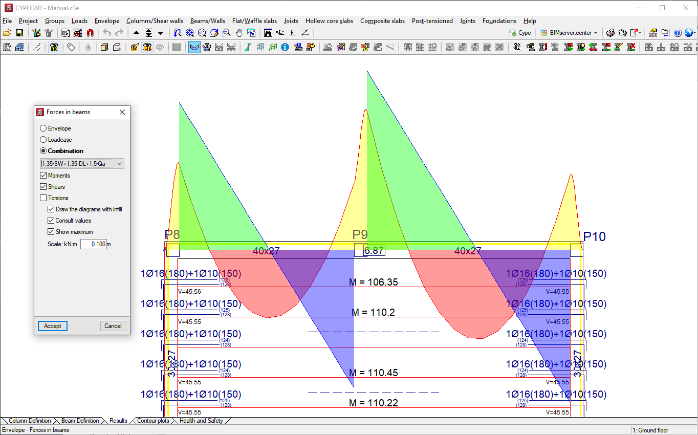
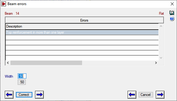
Once the analysis has finished, CYPECAD displays beams with errors in two different colours. The program classifies the errors into three groups: important, minor and negligible (the program does not warn of the latter). Users can vary this classification in accordance with their criteria. The meaning of each error is explained using the help dialogues within the program.
Beams marked with errors can be selected so the program can explain what problems they have.
Drawings and reports
CYPECAD generates beam reinforcement drawings, and force, reinforcement, measurement and beam label reports. Additionally, if the selected concrete and seismic code (if applicable) allows the Advanced beam editor to be used, the program also generates detailed Ultimate Limit State and Serviceability Limit State (U.L.S. and S.L.S.) check reports for concrete beams.
CYPECAD versions
CYPECAD is available in its unlimited version and also in two limited versions called LT30 and LT50, which contain the same tools and module acquisition possibilities, but have the following conditions:
CYPECAD LT50:
- Fifty columns.
- Four floor groups (Floor group: floors which are the same and consecutive).
- Total of five floors.
- Walls: one hundred linear metres. Feature available with the Building walls module.
CYPECAD LT30:
- Thirty columns.
- Four floor groups (Floor group: floors which are the same and consecutive).
- Total of five floors.
- Walls: one hundred linear metres. Feature available with the Building walls module.
Integrated 3D structures of CYPECAD (also LT50 and LT30) is not technically a module. To define these 3D structures in CYPECAD, users must also have the required permits to use CYPE 3D in their user license and, optionally, modules that are exclusive to CYPE 3D.
Other features
In order to access further features offered by the program, there are several modules that can be found on the "CYPECAD modules" and "CYPE 3D modules" webpages.