

Mat foundations and foundation beams
To analyse and design mat foundations and foundation beams in CYPECAD users must use the "Mat foundations and foundation beams" module.
Entering mat foundations and foundation beams
The process of entering mat foundations and foundation beams in CYPECAD is intuitive and is carried out using the program's graphical interface. The geometry of the mat foundations and beams can be defined, the materials used can be specified and the loads relevant for the structural analysis can be applied. The flexibility of the program allows users to enter various types of foundations, making it possible to adapt the program to the specific needs of each project.
The steps to be followed for entering mat foundations and foundation beams in the analysis are, in short, as follows:
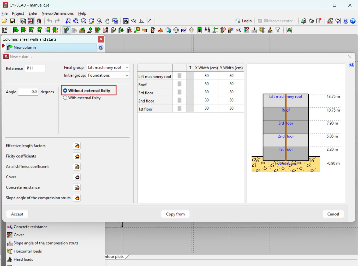
- In the"Columns definition" tab the columns must be defined by specifying "Without external fixity", as they will be supported on the mat foundations or foundation beam. The page for concrete columns provides more information on how to dimension reinforced concrete columns with rectangular and circular cross sections.
- In the "Beam definition" tab, users must carry out the following:
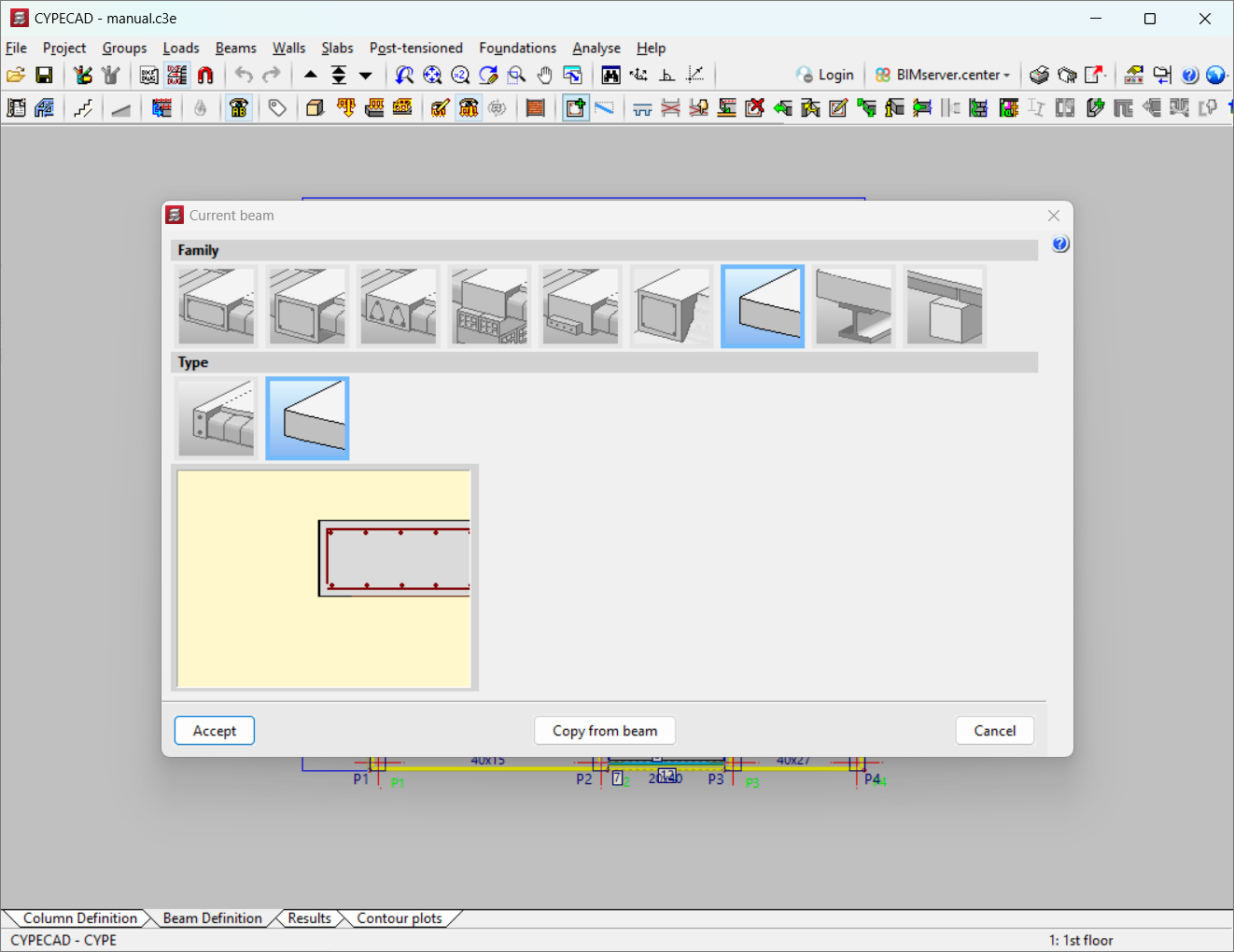
- Set the slab contour with the flat foundation beam element (approx. 40 cm wide) or with a limit beam (width 0) by selecting it under "Current beam". An alternative option is to enter the basement walls. This is explained in the "Entering mat foundations or foundation beams" section.
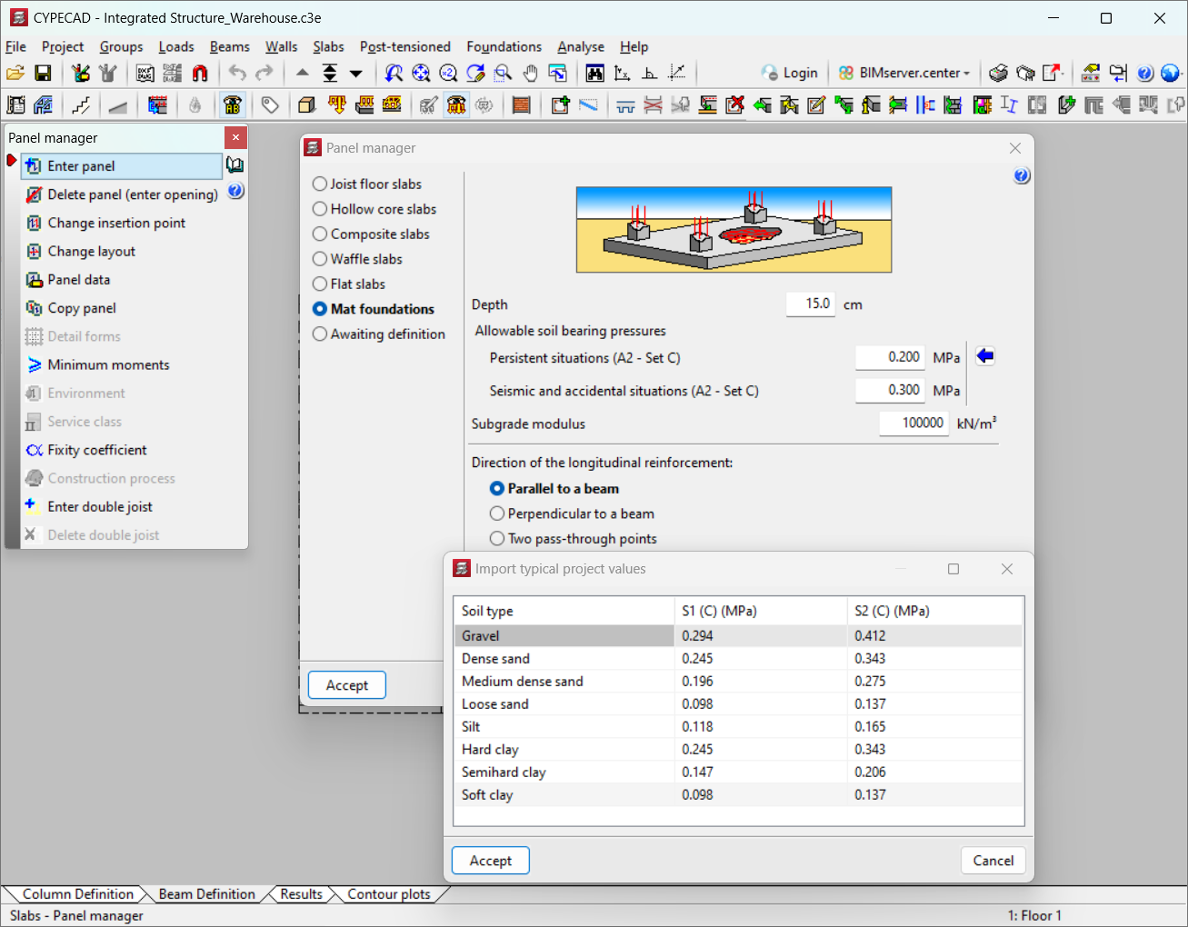
- Enter a "Mat foundation" layer with the "Panels" option. Users can define the depth, the allowable soil bearing pressures, the subgrade modulus and the direction of longitudinal reinforcement. This is explained in the "Data of the foundation slab layer" section.
- If the slab has surface loads and linear loads, they must be added with the "Loads" option.
Entering foundation beams or limit beams
In the "Current beam" dialogue box, which can be accessed by clicking on the "Beams" menu and then on "Enter beam", users can select the "Foundation beams" or "Non-structural or limit beam" family.
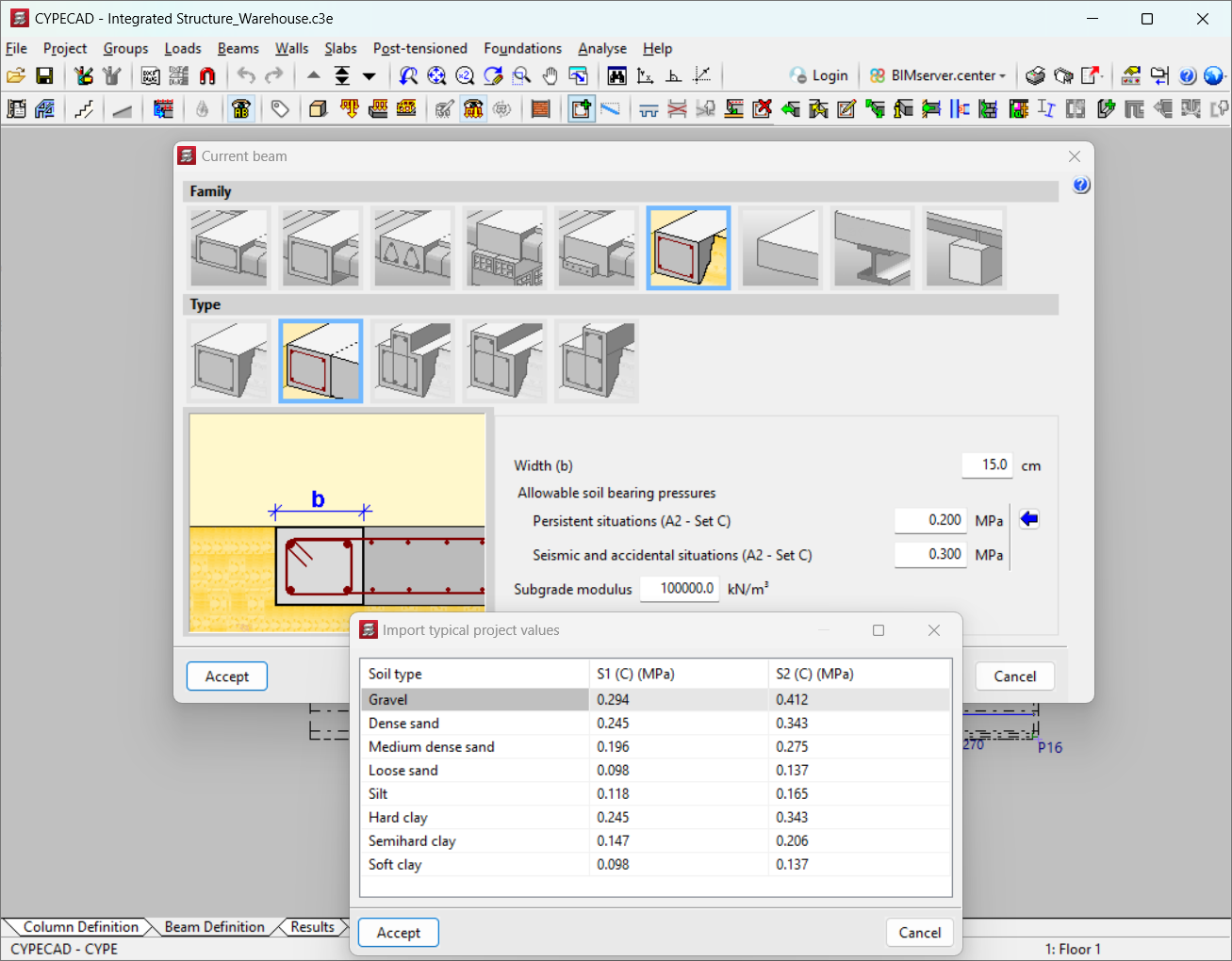
When selecting "Non-structural beam or limit beam", no additional data needs to be defined. For "Flat foundation beam" type foundation beams, on the other hand, the following data needs to be set:
- Width (b)
The total width of the beam must be defined in centimetres. - Allowable soil bearing pressures
The values for persistent, seismic and accidental situations must be specified. Usual project values can be imported using the blue arrow. - Subgrade modulus
The subgrade modulus or subgrade coefficient of the soil needs to be established.
Data from the foundation beam panel
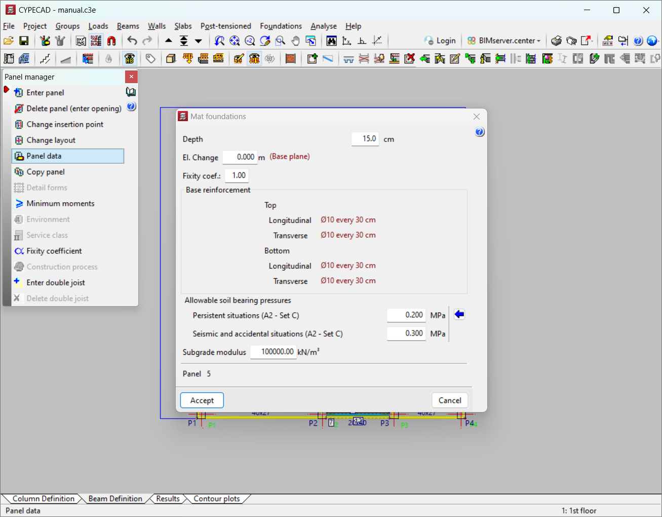
The following data can be modified in the "Mat foundations" dialogue box, which can be accessed via the "Slabs" menu and then selecting "Panel manager" and "Panel data":
- "Depth", "Elevation change", "Fixity coefficient" and "Base reinforcement" allow users to modify the depth of the slab, the elevation change with respect to the level at which the floor has been entered in "Panel data", the fixity coefficient with the axis of the beam on which it rests and, finally, the base reinforcement assigned by default according to the depth, or manually assigned by the user in the "Base reinforcement" option.
- "Allowable soil bearing pressures" and "Subgrade modulus"
They allow users to modify the subgrade modulus and the allowable soil bearing pressures initially assigned when the panel was entered.
Analysis and design process for mat foundations and foundation beams
The mat foundations and foundation beams are analysed as another element in the structure, thus analysing the foundations with the structure.
The mat foundations and foundation beams are considered to be supported on an elastic soil (subgrade coefficient method), according to the Winkler model, based on a constant of proportionality between forces and displacements, the value of which is the subgrade coefficient.
Mat foundations and foundation beams are part of the overall structure and therefore interact with the rest of the structure (they are part of the overall stiffness matrix of the structure). Therefore, loads can be applied to these elements and any slab or beam of the structure they are part of.
The limit states to be checked are those corresponding to the design of reinforced concrete elements (ultimate limit states) and to the checking of stresses, equilibrium and uplifts (serviceability limit states).
Results output
They are checked in the same way as normal slabs and beams, and modifications can be applied and drawings can be obtained using the same methodology.
Foundation beam results:
- Defined base reinforcement which may be modified by analysis, if necessary.
- Meshing of discretised elements.
- Diagram of envelopes of reinforcement areas required per metre width, in the defined reinforcement directions, top and bottom.
- Displacements in millimetres. By loadcase of any node.
- Forces by loadcase for any node, and the reinforcement ratio required by design in each direction of reinforcement.
- Maximum displacement per panel and loadcase. Not to be confused with deflections. For foundation beams, the entries are specified. If they are positive, there is an uplift, and the analysis would not be correct, with the theory applied.
- Checking the reinforcement obtained in any longitudinal, transverse, top and bottom direction and the defined base reinforcement, if any.
- Checking and reinforcement, if necessary, punching and shear reinforcement of the solid areas and ribs of the lightweight area.
- Matching reinforcement in any direction to maximum values in ratio and length.
- Modifying longitudinal reinforcement in any direction, if applicable, in number, diameters, spacing, lengths and bends.
- Excessive stresses in foundation beams.
- Contour plots and contour lines of forces, displacements and ratios.
- Reports of beam reinforcement, beam quantities, tags, beam reinforcement detailing, and U.L.S. checks of columns and beams, among others.
- Foundation beam drawings.
Foundation beams results:
- Active deflection and other deflections, deflection-to-light ratio, consideration of minimum moments.
- Beam envelopes with and without seismic loads, with bending moments, shear forces and torsional moments. They can be measured graphically and numerically.
- Reinforcing beams, considering the number of rounds, the diameter, the lengths and the stirrups with their lengths. These results can be modified. Users can check the top and bottom reinforcement areas, required and analysed, both longitudinal and transverse.
- Errors in beams: excessive deflection, spacing between bars, anchor lengths, compressed reinforcement, and oblique compression by shear force and/or bending moments and all other data on inadequate design or reinforcement. Colour codes can be assigned to assess their importance.
- Fixity coefficient at beam edges.
- Slab reinforcement report, displacements at slab and waffle nodes, forces at slab and waffle nodes, among others.
- Foundation floor plans and contour plot floor plans.
User license
For CYPECAD to be able to analyse and design mat foundations and foundation beams, the user license must include the "Mat foundations and foundation beams" module in addition to CYPECAD.
Other features
To have access to other features offered by the program, there are several modules which can be found on the "CYPECAD modules" page.