
Flat slabs
With the "Flat slabs" module, CYPECAD analyses and designs flat floor slabs.
The discretisation of the flat slab panels is carried out on meshes of bar elements with a maximum size of 25 cm, and a static condensation (exact method) of all degrees of freedom is carried out. Shear deformation is considered and the rigid diaphragm load case is maintained. The torsional stiffness of the elements is considered.
Entering flat slabs
To select the "Flat slabs" type, click on the "Layer" menu and then on "Layer management". Here, the "Enter panel" option opens the "Panel manager" window, in which "Flat slabs" can be selected.
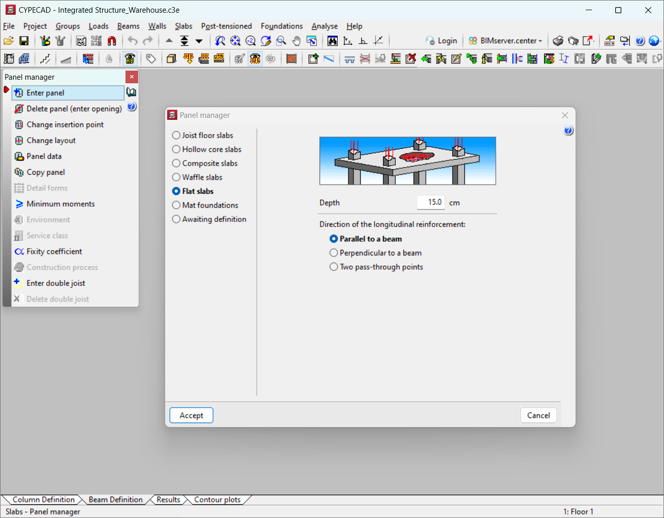
The following data must be defined when entering "Flat slabs" type panels:
- Depth
The depth of the panel must be stated in centimetres. Each panel can have a different depth. - Direction of the longitudinal reinforcement
Three layout options are available: "Parallel to a beam", "Perpendicular to a beam" and "Two pass-through points".
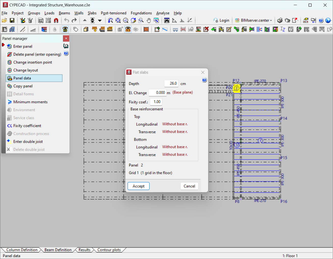
Flat slab panel data
Under "Panel data" a fixity coefficient can be applied for any flat slab panel at its edge connection to the beams it rests on, which can vary between 0 (hinged) and 1 (fixed), as well as intermediate values (semi-fixed).
Similarly, differences in level can be defined between panels for drawing purposes and the detailing reinforcement of floor slabs and beams, affecting the height of supports passing through the beam at the change of level. If the beam is flat, it will become an edge beam.
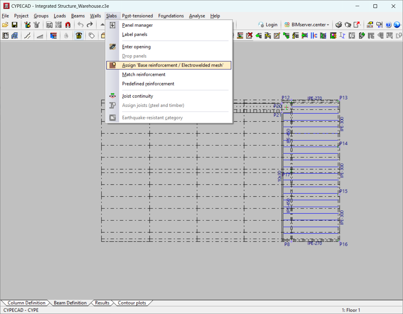
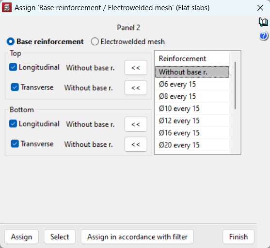
By default, flat slab panels appear "Without base r(einforcement)". To assign a base reinforcement in both the top and bottom direction, it must be defined in the "Layers" menu under "Assign 'Base reinforcement / Electrowelded mesh' (Flat slabs)".
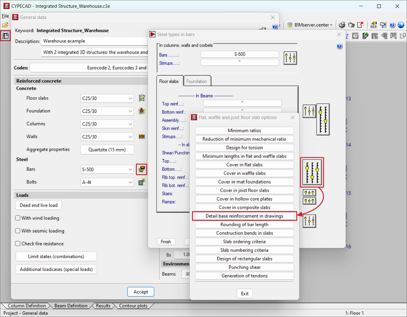
Detailing base reinforcement in drawings
If the base reinforcement is considered, remember to activate the analysis option "Detail base reinforcement in drawings", which can be found in the "Project" menu, by going to "General data", "By position" and "Options" for the reinforcement of waffle slabs and joist floor slabs.
If this option is not activated, the base reinforcement will not be visible and only the reinforcement will be shown. Therefore, this reinforcement will not be measured in reports or drawing quantity tables. When launching drawings users must ensure that the presence and consideration of the base reinforcement are recorded. Drawings should be reviewed and details added to indicate overlap lengths and areas where it can be implemented.
If the option is activated, the base reinforcement will be displayed as an additional reinforcement, and it can be edited and modified.
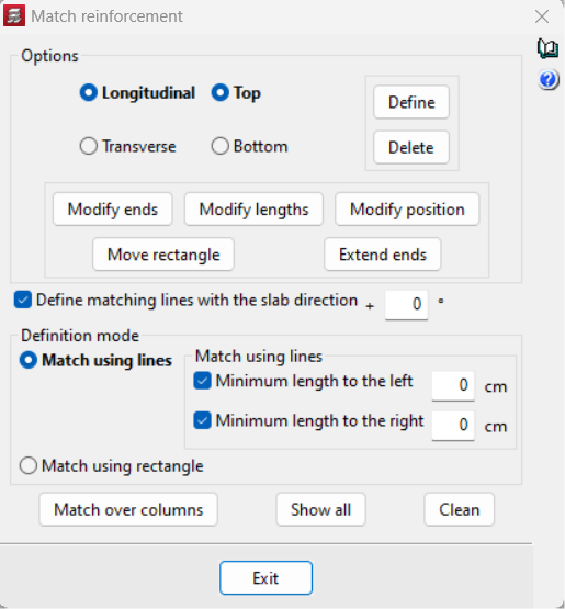
Matching the reinforcement
To adjust the reinforcement of a flat slab panel after the analysis, use "Match reinforcement" in the "Layers" menu. In the option box, select the reinforcement (longitudinal or transverse, top or bottom) and choose the matching mode (line or rectangle). When matching by lines, minimum lengths can be set on both sides. Other options include entering lines with a specific angle or with any angle, the modification of ends, lengths and positions, the ability to automatically equalise negatives on columns, or the possibility of reassembling the slabs after entering the matching lines, among others.
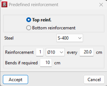
Default reinforcement
Using this option, users can enter strengthening reinforcement for floor slabs in any direction. A different type of steel than the one selected for the main reinforcement of the slab can be entered. The program will deduct the contribution of the default reinforcement from the total design so that each reinforcement design will be adjusted by subtracting the average mechanical capacity of the entered default reinforcement. The term 'average mechanical capacity of the default reinforcement' refers to the total mechanical capacity of the entered default reinforcement divided by the width of the area in which the default reinforcement is placed.
Results output
The program shows the following results for flat slabs:
- Contour plots and contour lines
Displacements, forces and ratios in cm²/m can be displayed for all panels in any group. - Structural floor plans
Reinforcement drawings can be obtained for flat slabs, detailing the base reinforcement in a table. A summary table with quantities and totals can be provided. - Reports
Allows users to extract the "Slab reinforcement" report.
User license
For CYPECAD to be able to analyse and design flat slabs, the user license must include the "Flat slabs" module in addition to CYPECAD.
Other features
To have access to other features offered by the program, there are several modules which can be found on the "CYPECAD modules" page.