

Timber sections
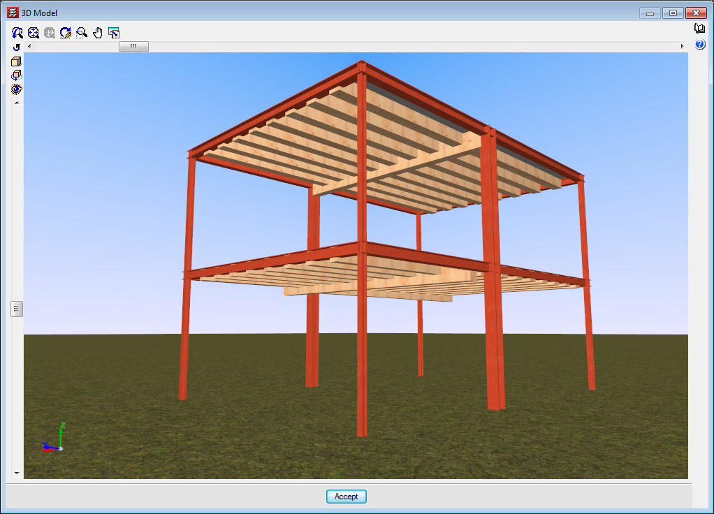
Using the “Analysis of timber structures” module, CYPECAD and CYPE 3D analyse and design timber beams and generic bars.
More information on the analysis and design of timber joist floor slabs can be found on the “Timber joist floor slabs”
General properties of timber elements in CYPECAD
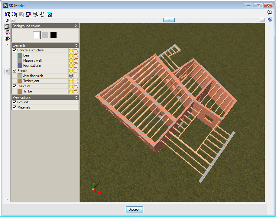
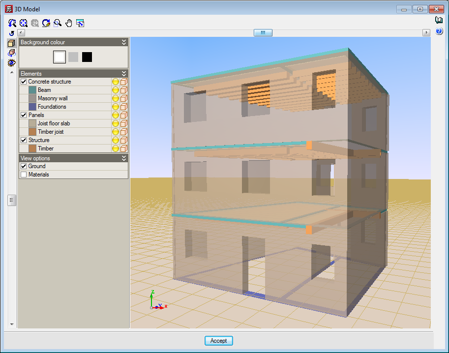
CYPECAD allows users to define, analyse and design timber beams and timber joist floor slabs. These structural timber elements are included in the “Analysis of timber structures” and “Timber joist floor slabs” modules, respectively.
The “Analysis of timber structures” module is for CYPECAD and CYPE 3D and allows users to analyse and design structural beam-type timber elements and generic-type timber elements. More information on the structural types of bars that can be entered in CYPE 3D and integrated structures of CYPECAD can be found in the section on “Bar structure types in CYPE 3D” on the CYPE 3D webpage.
More information on timber joist floor slabs can be found on the Timber joist floor slabs webpage.
Implemented codes
The codes implemented for the design and check of the timber joist floor slabs and beams are:
- ANSI/AWC NDS – 2015 (ASD) (USA)
- CIRSOC 601 (Argentina)
- CTE-DB-SE-M (Spain)
- Eurocode 5
- Eurocode 5 France
- Eurocode 5 Belgium
- NBR 7190:1997 (Brazil)
Section series
To adapt the program to the current market, timber sections have been created, distinguishing between sawn timber and laminated timber, and including the DUO/TRIO series, which are currently very much in use.
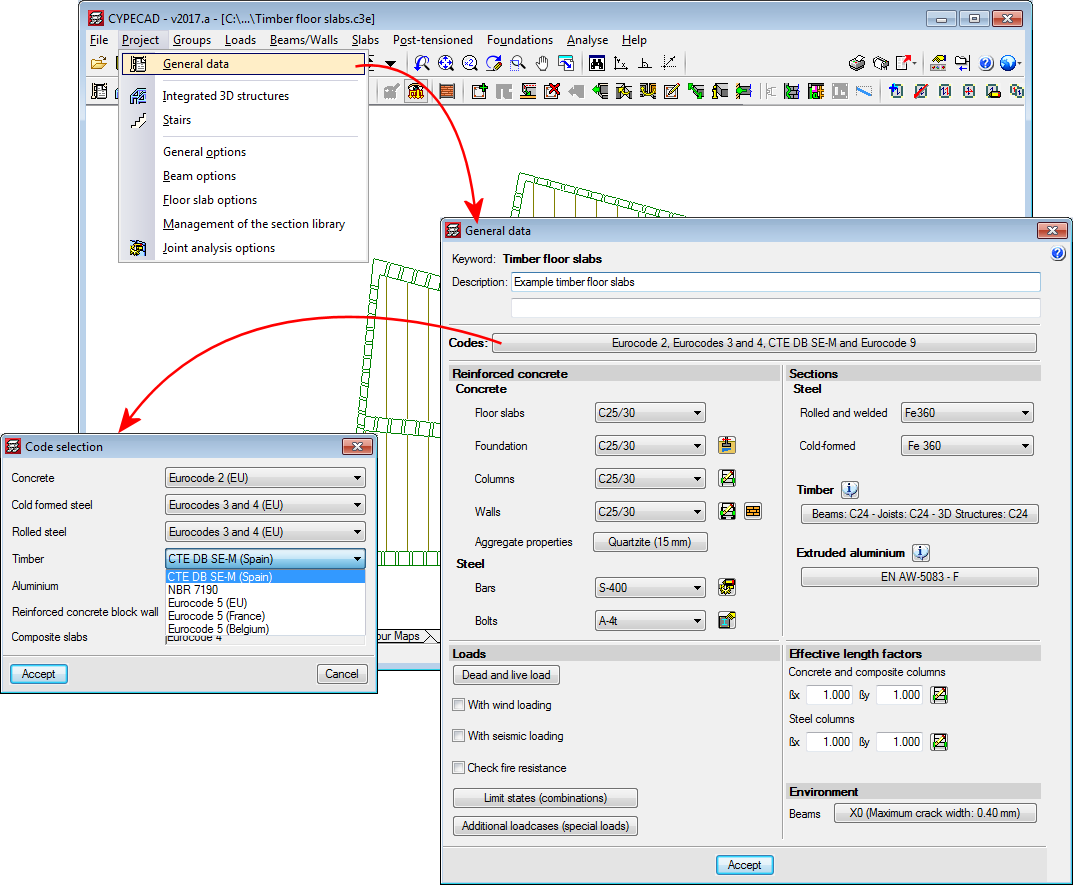
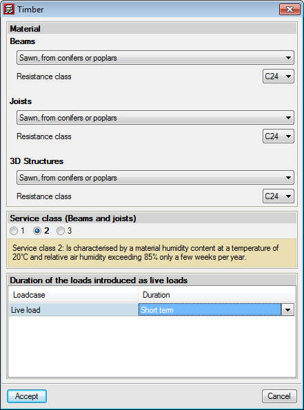
Definition of the material, service class and live load duration
In the "Timber" dialog boxes in CYPECAD and CYPE 3D (menu Work > General data > timber), users can define the data used by both programs in the analysis of timber structural elements (beams, generic type bars in CYPE 3D or integrated 3D structures in CYPECAD, and one-way floor slab joists -only in CYPECAD):
- Material properties
In CYPECAD, this data is defined individually for beams, joists, and bars of 3D Structures. In CYPE 3D, the defined material affects timber structural elements of both "Beam" and "Generic" types of structural elements. Nevertheless, in CYPECAD and CYPE 3D, each generic beam or bar can have different material properties. Depending on the code used, the properties that have to be defined and the options available for each property will vary:
- Type
- Origin
- Resistance class
- Category
- “Service class” or “Humidity class”
In CYPECAD, the service class defined applies to beams, joists and timber bars of 3D structures, and in CYPE 3D, it applies to timber beams and generic bars. - Duration of loads entered as live loads
The duration of live loads which affect timber elements is also applicable to any timber element defined in CYPECAD and CYPE 3D.
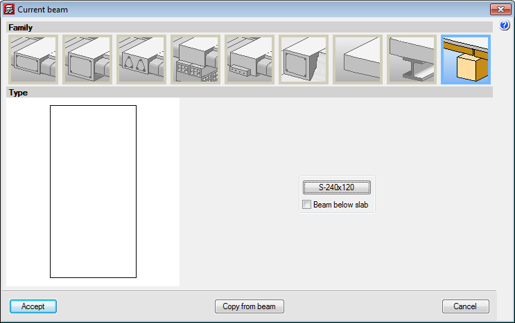
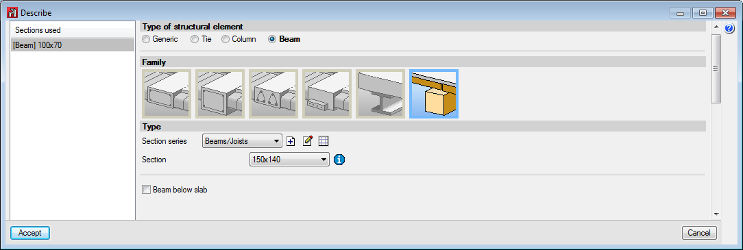
Entering timber beams
In the “Current beam” dialog box of CYPECAD (Beam definition tab > Panels > Beams/Walls > Define beam > Timber beams), and in the CYPE 3D dialog box "Describe" (Bar > New beam > Default beam > Timber beams), users can enter timber beams.
Entering timber beams as structural elements in CYPECAD and CYPE 3D instead of as generic timber bars allows users to use the Advanced beam editor to edit and design these elements.
In CYPECAD, users can define timber beams as “Beam below slab”. In this case, if the timber beam limits timber joist floor slabs, it will be placed below the maximum depth of the floor slab. More information on the elements, which include the maximum depth of a timber joist floor slab, can be found in the “Entering timber joist floor slabs” section of the “Timber joist floor slabs” webpage.

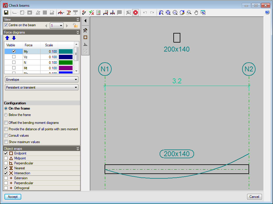
Timber beams design (worst case check reports)
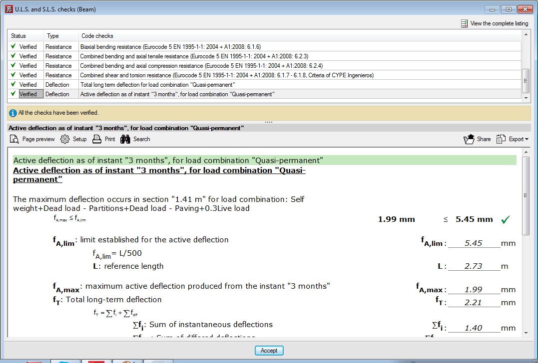
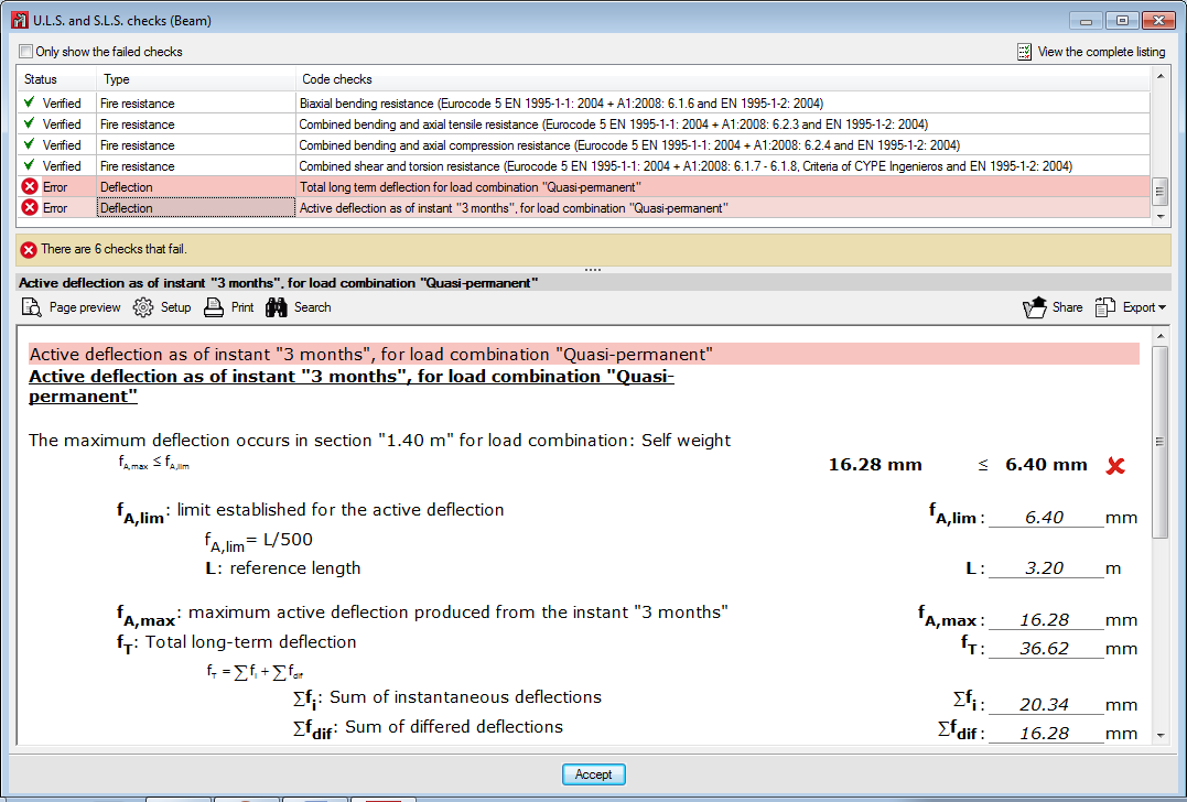
From the “Beams” menu in the “Results” tab, users can access the worst-case checks of beams. This report includes the deflection checks of the timber beams.
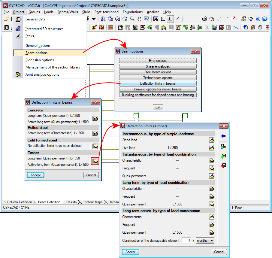
These deflection checks are obtained bearing in mind the deflection limits defined in “Beam options” (Project > Beam options).
Entering timber beams as structural elements in CYPECAD and CYPE 3D, instead of as generic timber bars, allows users to use the Advanced beam editor to edit and design these elements.
Fire resistance check of timber beams
The program carries out the fire resistance check of timber elements of CYPECAD and CYPE 3D (timber beams, timber joist floor slabs, and generic timber bars in integrated 3D structures and in CYPE 3D) using the “Fire resistance check” module, which also carries out this check for steel and concrete structural elements.
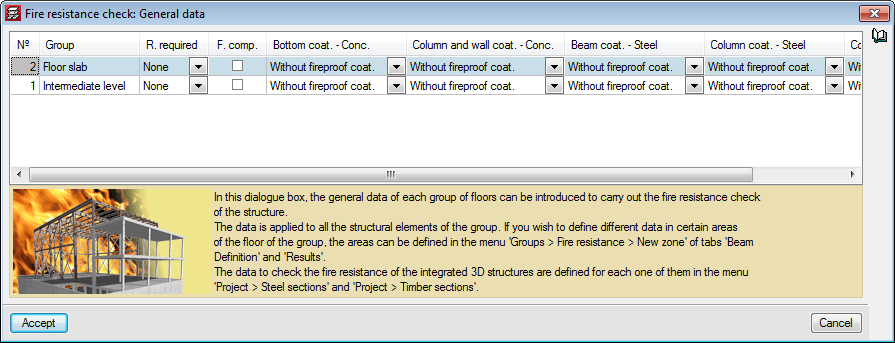
The data that has to be defined for CYPECAD to be able to check the fire resistance of timber joists and beams is entered in the “Fire resistance check. General data” dialog box (Project > General data > Loads > Fire resistance check).
In this dialog box, users have to define, for each floor group:
- The required resistance
- Whether or not floor slabs are acting as compartments
- The coatings of the structural elements:
- Bottom coating of concrete beams and floor slabs
- Coating of columns, shear walls and walls
- Coating of steel beams and joists
- Coating of steel columns
- Coating of timber beams and joists
More information on this module, for use with CYPECAD and CYPE 3D, can be found on the Fire resistance check in CYPE programs webpage.
User license
For CYPECAD and CYPE 3D to be able to analyse and design timber joist floor slabs, the user license must include the “Analysis of timber structures” module as well as the permits corresponding to CYPECAD and/or CYPE 3D.
If users also wish to check the fire resistance of these elements, they must also hold the “Fire resistance check” module permits.
CYPECAD versions
CYPECAD is available in its unlimited version and also in two limited versions called LT30 and LT50, which contain the same tools and module acquisition possibilities, but have the following conditions:
CYPECAD LT50:
- Fifty columns
- Four floor groups (Floor group: floors which are the same and consecutive)
- Total of five floors
- Walls: one hundred linear metres
CYPECAD LT30:
- Thirty columns
- Four floor groups (Floor group: floors which are the same and consecutive)
- Total of five floors
- Walls: one hundred linear metres
Integrated 3D structures of CYPECAD (also LT50 and LT30) is not technically a module. To define these 3D structures in CYPECAD, users must also have the required permits to use CYPE 3D in their user license and, optionally, modules that are exclusive to CYPE 3D.
Other features
To access further features offered by the program, several modules can be found on the “CYPECAD modules” webpage.