
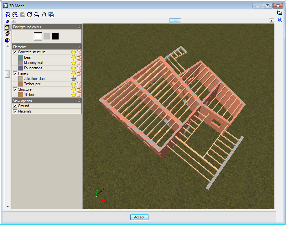
Timber joist floor slabs
Using the “Timber joist floor slabs” module, CYPECAD analyses and designs timber joist floor slabs.
General properties of timber elements in CYPECAD
CYPECAD allows users to define, analyse and design timber joist floor slabs and timber beams. These structural timber elements are included in the “Timber joist floor slabs” and “Analysis of timber structures” modules, respectively.
The “Analysis of timber structures” module can be used in CYPECAD and CYPE 3D and allows users to analyse and design structural beam-type timber elements and generic-type timber elements. More information on the “Analysis of timber structures” module, to be used in CYPECAD and CYPE 3D, can be found on the “Timber sections” webpage.
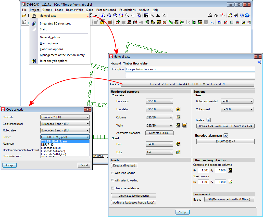
Implemented codes
The codes implemented for the design and check of the timber joist floor slabs and beams are:
- ANSI/AWC NDS – 2015 (ASD) (USA)
- CIRSOC 601 (Argentina)
- CTE-DB -SE-M (Spain)
- Eurocode 5
- Eurocode 5 France
- Eurocode 5 Belgium
- NBR 7190:1997 (Brazil)
Section series
To adapt the program to the current market, timber sections have been created, distinguishing between sawn timber and laminated timber, and including the DUO/TRIO series, which are currently very much in use.
Defining the material, service class and live load duration
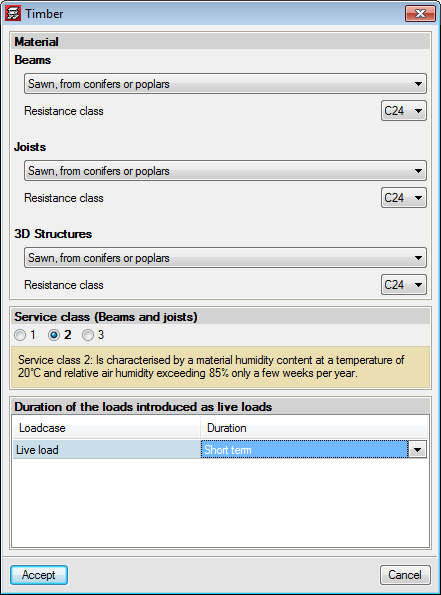
The data CYPECAD will use to analyse the timber elements (joists, beams and bars of integrated 3D structures) is defined in the “Timber” dialog box (Project > General data > Timber):
- Material properties
This data is defined individually for beams, joists and bars of 3D structures. The properties that have to be defined vary and the options that are available for each property will depend on the code that is applied:
- Type
- Origin
- Resistance class
- Category
- "Service class” or “Humidity class”
The service class defined applies to beams, joists and timber bars of 3D structures. - Duration of loads entered as live loads
The duration of live loads which affect timber elements is also applicable to any timber element defined in CYPECAD.
Entering timber joist floor slabs
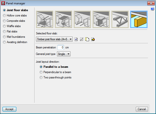
Users can select timber joist floor slabs in the “Joist floor slabs” menu in the “Panel manager” dialog box (Slabs > Panel manager > Define panel).
The following data must be defined for a joist floor slab:
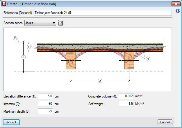
- Section series
The timber section series to be used in the design of the timber joists is indicated here.
Elevation difference
This is the depth of the space between joists which, for the program, is generic (regardless of its aspect: curved vault, flat ceramic board, etc.) and its height is measured from the top surface of the timber joist up to the level of floor “Z”. - Interaxis
- Maximum depth
The maximum depth of the floor slab is defined by users and takes into account the height of the space between joists. - Concrete volume
This is only used for the take-off. - Self-weight of the floor slab
Timber joist design (worst case check reports)
The sections that make up the timber joists are designed for simple bending as, due to the rigid diaphragm hypothesis, axial forces and forces in the plane of the floor slab are not considered.
Following these criteria, the program selects the first joist of the selected series that does not fail any resistance or deflection checks, as long as the maximum depth (defined by users) is not exceeded.
From the “Joists” menu in the “Results” tabs, users can access the worst-case report of the joist. This report includes a table with the deflection checks of the timber joists.
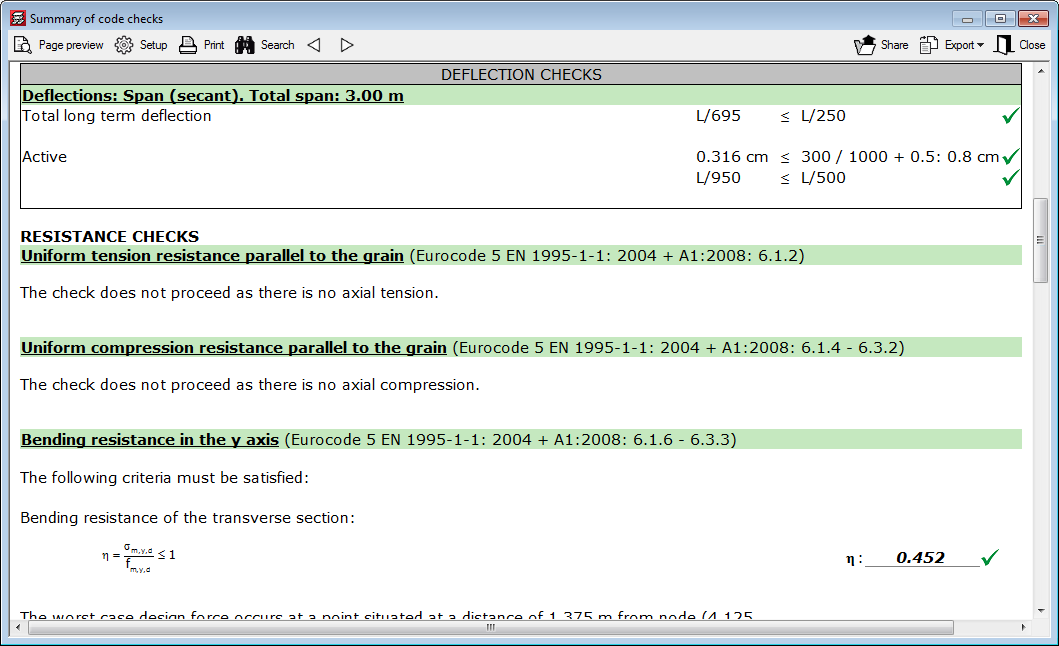
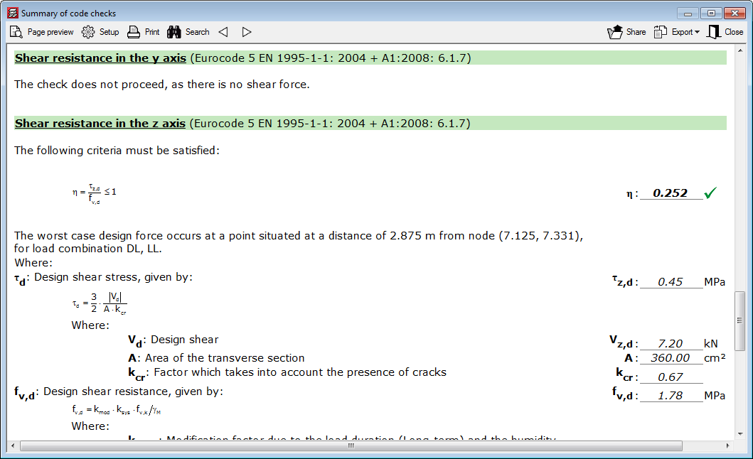
The deflection checks for timber joists are obtained considering:
- The deflection limits for the joist
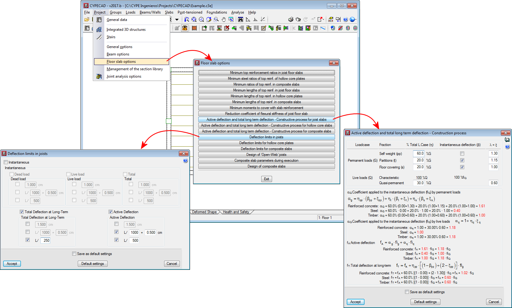
These limits are indicated in the “Deflection limits in joists” dialog box (Project > Floor slab options). - The active deflection and long-term deflection
These depend on the construction process and the coefficients which are applied. These are established in the “Active deflection and total long-term deflection – Construction process for joist floor slabs” dialog box (Project > Floor slab options > Active deflection and total long-term deflection – Construction process for joist floor slabs).
These coefficients take into account the construction process when calculating the active and long-term deflections for concrete, steel and timber joists. Here, users can see the equivalent equation to consider creep in timber joists, which considers the creep coefficients automatically defined in timber design codes, depending on their service or humidity class.
More information on the analysis process applied to obtain the active deflection and long-term deflection carried out by CYPECAD can be found by pressing the help button in this dialog box (located in the top right-hand corner of the dialog box).
Fire resistance check of timber joists
The program carries out the fire resistance check of timber joists using the “Structural fire resistance” module, used by CYPECAD and CYPE 3D, and also carries out the check for other structural timber (timber beams and other generic-type timber structural elements), steel and concrete elements.
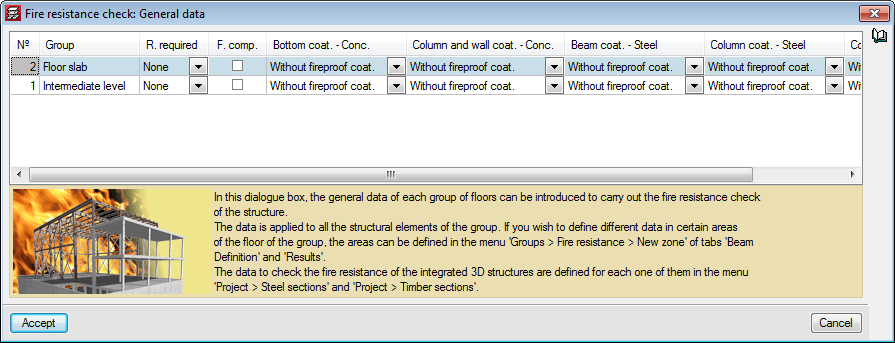
The data that has to be defined for CYPECAD to be able to check the fire resistance of timber joists and beams is entered in the “Fire resistance check. General data” dialog box (Project > General data > Loads > Fire resistance check).
In this dialog box, users must define the following for each floor group:
- The required resistance
- Whether or not floor slabs are acting as compartments
- The coatings of the structural elements:
- Bottom coating of concrete beams and floor slabs
- Coating of columns, shear walls and walls
- Coating of steel beams and joists
- Coating of steel columns
- Coating of timber beams and joists
Different data can be defined for a specific zone in a group of floors using the options of the Fire resistance window (Groups > Fire resistance from the Beam Definition or Results tab).
More information on this module, for use with CYPECAD and CYPE 3D, can be found on the Fire resistance check in CYPE programs webpage.
User license
For CYPECAD to be able to analyse and design timber joist floor slabs, the user licence must include, as well as CYPECAD, the “CYPECAD” and “Joist floor slabs” modules.
Should users wish to check the fire resistance of these elements, they must also have the “Structural fire resistance” module permits.
Other features
To access further features offered by the program, several modules can be found on the “CYPECAD modules” webpage.