Fire resistance check in CYPE programs
The "Structural fire resistance" module carries out, in CYPECAD and CYPE 3D, the fire resistance check and design of sections or protection cover depending on the material in question:
- For steel and concrete structural elements
The "Structural fire resistance" module carries out the fire resistance check and design for steel and concrete structural elements in CYPECAD and steel bars (linear elements) in CYPE 3D. - For timber sections
The "Structural fire resistance" module designs timber sections against fire action, so they comply with the code selected in CYPECAD, CYPE 3D and Integrated 3D structures of CYPECAD.
Fire resistance check of steel and concrete structural elements
General properties
Using the "Structural fire resistance" module, CYPECAD and CYPE 3D carry out the fire resistance check and design the protection cover of the steel and concrete structural elements in the job in accordance with the ABNT NBR 15200:2012 (Brazil), CTE DB SI 6 (Spain), Eurocode 2 (EN 1992-1-2:2004), Eurocode 3 (EN 1993-1-2:2005) and ACI 216-1-07 (USA) codes.
- In CYPECAD, the "Structural fire resistance" module carries out the aforementioned check and design for:
- Beams, floor slabs, columns and concrete walls.
- Steel beams and columns.
- Steel bars in Integrated 3D structures of CYPECAD.
CYPECAD does not carry out the fire resistance check for concrete block walls or for composite slabs.
- In CYPE 3D, the "Structural fire resistance" module carries out the check and design for steel bars.
Checks and designs carried out
The "Structural fire resistance" module carries out the following checks and design procedures:
- For structural elements for which a protection coating has been defined, the program will design the minimum required thickness of the coating so the requirements of the applied code are met.
- For the structural elements for which no protection coating has been defined, the program checks the element with the assigned fire resistance data.
- If a structural element has been assigned a coating and the program checks and finds it is not required to comply with the requirements of the applied code, the program will indicate that the coating of the structural element is not necessary, and so the minimum coating thickness will be applied for construction reasons.
Code selection
The code CYPECAD uses for checking the fire resistance of concrete structural elements (except for concrete block walls and composite slabs), depends on the selected concrete code:
- If Spanish code "EHE-CTE" is selected, CTE DB SI 6 is applied.
- If the concrete codes used in American countries are selected, the requirements of code ACI 216-1-07 are applied (excluding Brazil, where the code detailed in the following section is applied).
- If the Brazilian codes "ABNT NBR 6118:2014" or "ABNT NBR 6118:2007" are selected, the tabular method described in ABNT NBR 15200:2012 is applied.
- If any remaining concrete codes are selected, the Eurocode requirements are applied.
The code CYPECAD and CYPE 3D use to check the fire resistance of rolled and cold-formed steel structural elements depends on the selected steel code:
- With the Spanish "CTE DB SE-A" code, CTE DB SI 6 is applied.
- With Eurocodes 3 and 4, the Eurocode is applied.
- For the remaining rolled steel and cold-formed steel code, the programs do not currently perform a fire resistance check.
Data definition in CYPECAD
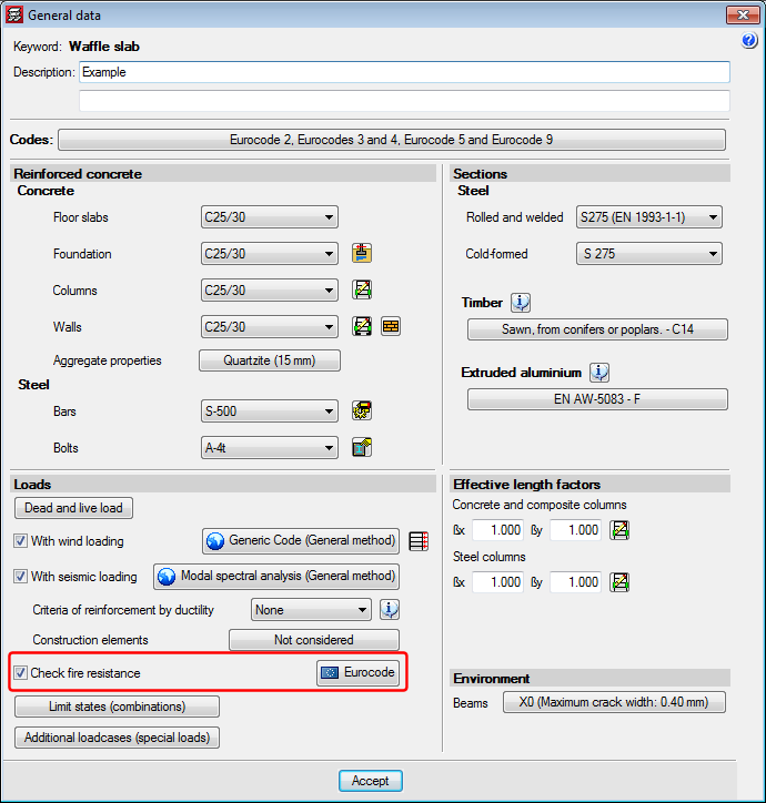
The fire resistance check in CYPECAD can be activated in the General data dialogue box (Job > General data).
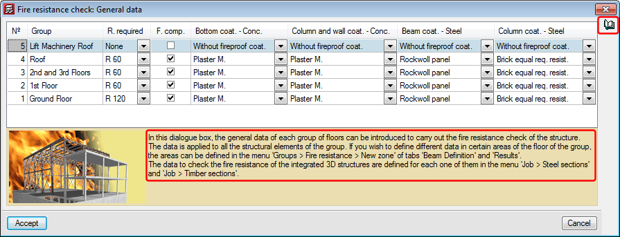
CYPECAD allows users to introduce the general data of each floor group (required resistance, floor slabs with or without compartmentalisation, and the coating of the construction elements) to carry out the fire resistance check of the structure.
It is possible to define different data for any zone of a floor group using the options in the Fire resistance window (Groups > Fire resistance check, in the Beam Definition or Results tab).
These tools allow users to:
 Define the data required to carry out the fire resistance of each group.
- Introduce a fire resistance check zone (polygonal or rectangular panel) with specific data. If data has been defined for a group and a zone is introduced, the program adopts the most unfavourable values between those of the group and those of the zone for each check. It is not possible to overlap zones.
- Edit a previously introduced zone.
- Move the vertices of a previously introduced zone.
- Delete one or several existing zones.
- Assign the type of protective coating for columns and concrete walls.
- Consult the type of protective coating for columns and concrete walls.
- Display the fire resistance check of the structural elements.
- Display a report with elements containing fire resistance errors or warnings.
All the dialogue boxes in which the properties of the construction elements for fire resistance checks are defined contain help tools describing their operation.
Data definition in CYPE 3D and Integrated 3D structures of CYPECAD
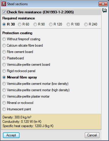
The data to check the fire resistance in CYPE 3D and in the Integrated 3D structures of CYPECAD is defined in Job > Steel sections.
Each integrated 3D structure of CYPECAD can have different data for the fire resistance check.
The dialogue boxes in which the properties of the construction elements for fire resistance checks are defined contain help tools describing their operation.
Fire resistance check of timber structural elements
General properties and applied codes
The "Structural fire resistance" module also carries out the fire resistance check for timber structural elements in CYPECAD, in the Integrated 3D structures of CYPECAD and in CYPE 3D. For timber sections, this module designs timber sections against fire action so they meet the requirements of the selected code: CTE DB SI 6 (Spain), NBR 7190 (Brazil) or Eurocode 5 (EN 1995-1-2:2004).
Data definition
The data used to check the fire resistance in CYPE 3D and in the Integrated 3D structures of CYPECAD is defined in Job > General data > Loads > Fire resistance.
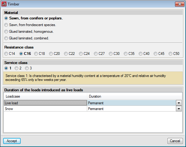
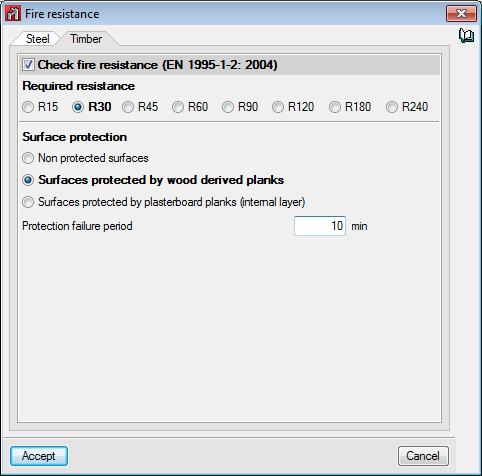
In the three programs, users define the type of timber, its resistance class and its service class (Job > General data > Timber sections); and must indicate the following parameters for their design against fire action:
- Required resistance. Required fire resistance time.
- Type of surface protection. Unprotected, protected by panels derived from wood or protected by plasterboard panels (internal layer).
- Protection failure period. If it exists.