Shells are flat two-dimensional elements with constant thickness and without openings, whose perimeter is defined by a polygon. They are entered and analysed in CYPE 3D and can be made of concrete, rolled steel, cold-formed steel, aluminium or generic material (specifying the modulus of elasticity and Poisson's ratio).
General properties of the shells
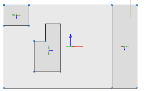
In CYPE 3D, shell elements can be defined. Shells are flat two-dimensional elements with constant thickness and without openings, whose perimeter is defined by a polygon.
For analysis purposes, shells are introduced in the global stiffness matrix of the structure using a three-dimensional finite element model composed of six-node (quadratic) triangular flat shells. The type of element used is based on the overlap of two locally decoupled elements: one provides the axial stiffness (membrane forces) and the other the bending stiffness (panel forces).
The following properties can be defined for each shell:
- Thickness and subgrade modulus
In the local Z axis direction. - Material
Concrete, rolled steel, cold-formed steel, aluminium and generic material (specifying the modulus of elasticity and Poisson’s ratio). - Position
With respect to the introduction plane. - Discretisation
The density of the mesh can be controlled by defining the maximum size of the triangle in the local x and y axes. - Direction of the axes
- Internal fixity
Internal fixity between the edges and other elements of the structure. - External fixity
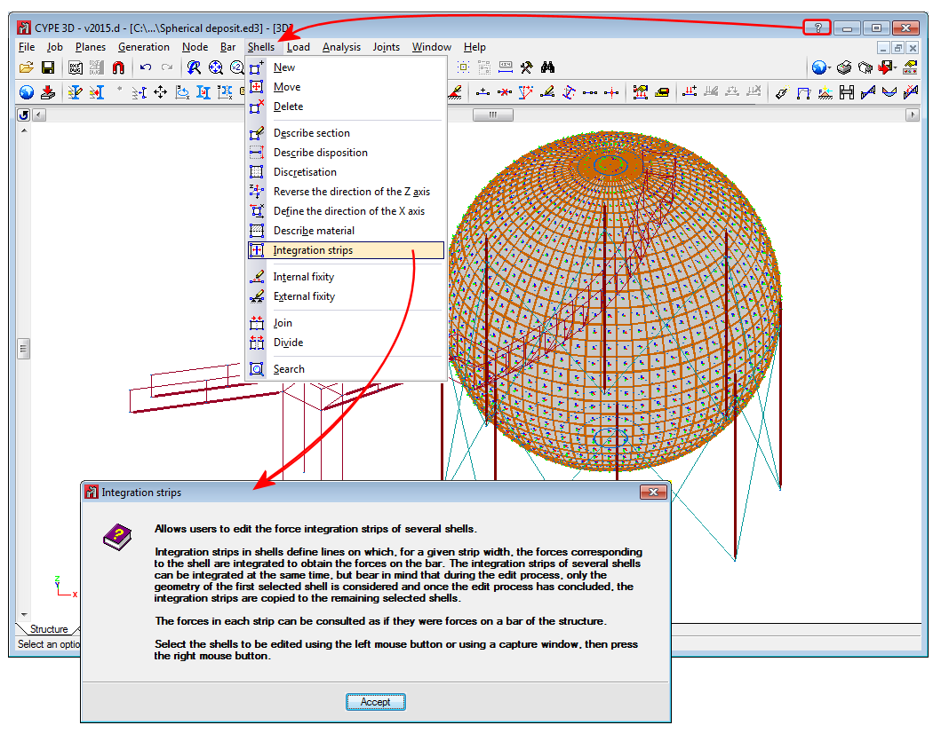
The external fixity of the edges can also be defined, but in this case, the fixity is applied to all the shells sharing that edge. The possible external fixity configurations are the same as those available for nodes in CYPE 3D. - Integration strips
Integration strips in shells define lines on which, for a given strip width, the forces corresponding to the shell are integrated to obtain the bar forces.

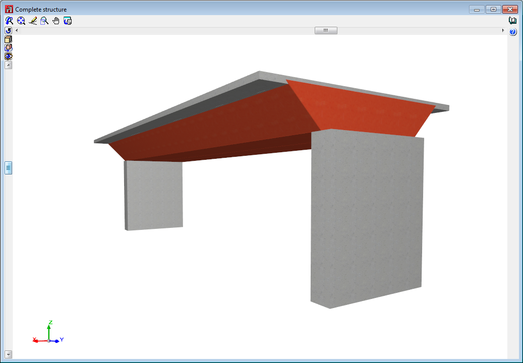
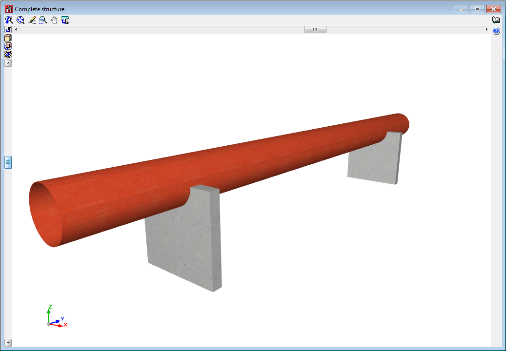
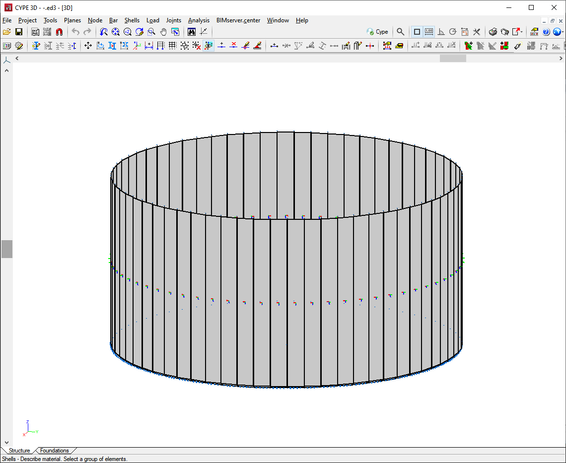
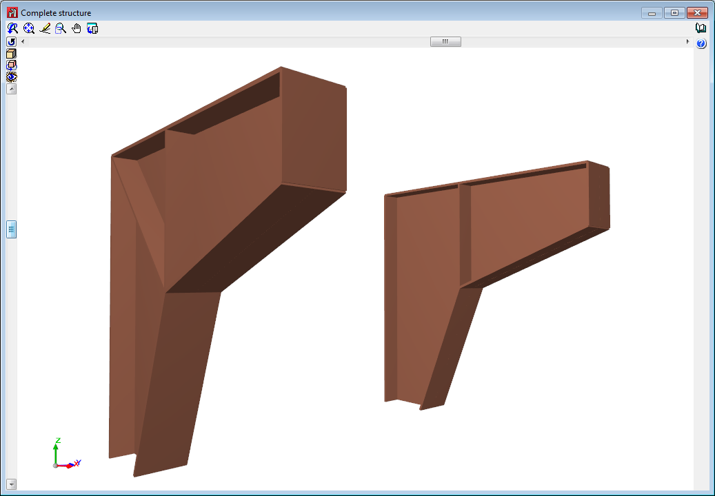
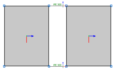
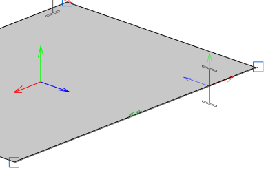
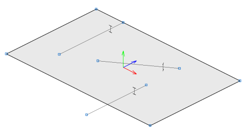
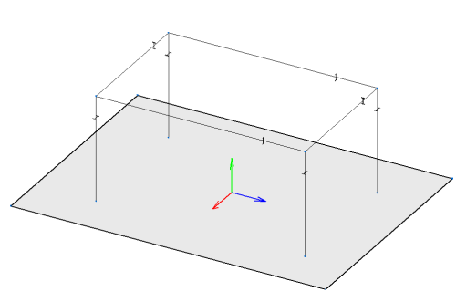
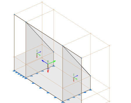
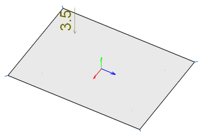
Below are some examples of structures created with shells in CYPE 3D:
Interaction with other elements
Interaction with other elements up to version 2016.f
Shells are connected to each other and to the rest of the structure by means of their edges. The possible interactions are:
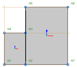
- Shell - Shell
Two shells are connected if they have an edge or several edges in common. In the following example, the plates are connected through the edge defined between nodes N2 and N3.
- Shell - Bar end
A bar can be connected to a shell via a common node.
- Shell - Bar edge
A bar is connected to a shell if it is completely contained in one of its edges.
Interaction with other elements as of version 2016.f
As well as the aforementioned possibilities of interaction of the shells and other elements, as of version 2016.g, the following are also possible:
- Shell - Interior bar
A bar is connected to a shell if it passes through it. The bar may be fully or partially contained.
- Shell - Interior bar end
A bar is connected to a shell if one of its end nodes is contained in the shell.
- Shell - Overlapping shell
A shell is connected to another shell if both are contained in the same plane and overlap each other. In the overlapping area, the properties and loads of the shell with the smaller area are applied.
In no case can a shell be completely covered by other shells.
- Shell edge - Interior shell
One shell connects to another shell in the portions of the edges of one that is contained within the other.
- Shell - Interior node
A node is connected to a shell if it is contained within it. The possibilities of editing the inner connection of such a node are the same as in any other case. This interaction makes it possible for users to introduce point loads in shells.
Data introduction
Geometric definition, material used, discretisation and integration strips
The “Shells” menu contains the options for introducing shell data (New, Move, Delete, Describe section, Describe disposition, Discretisation, Reverse the direction of the Z axis, Reverse the direction of the X axis, Describe material, Integration strips, Internal fixity, External fixity, Join, Divide, Search).
Each of these options provides help texts explaining how they work.
Importing text files
The text file import format (Tools menu > Import text files) has been extended in order to import shell elements. When this option is activated, a help text is displayed that provides information on the format that the text files must have in order to import a structure correctly.
Importing from DWG and DXF files
3DFace, Polyface mesh and Polygomesh entities are imported as shell elements in the layers where they are defined.

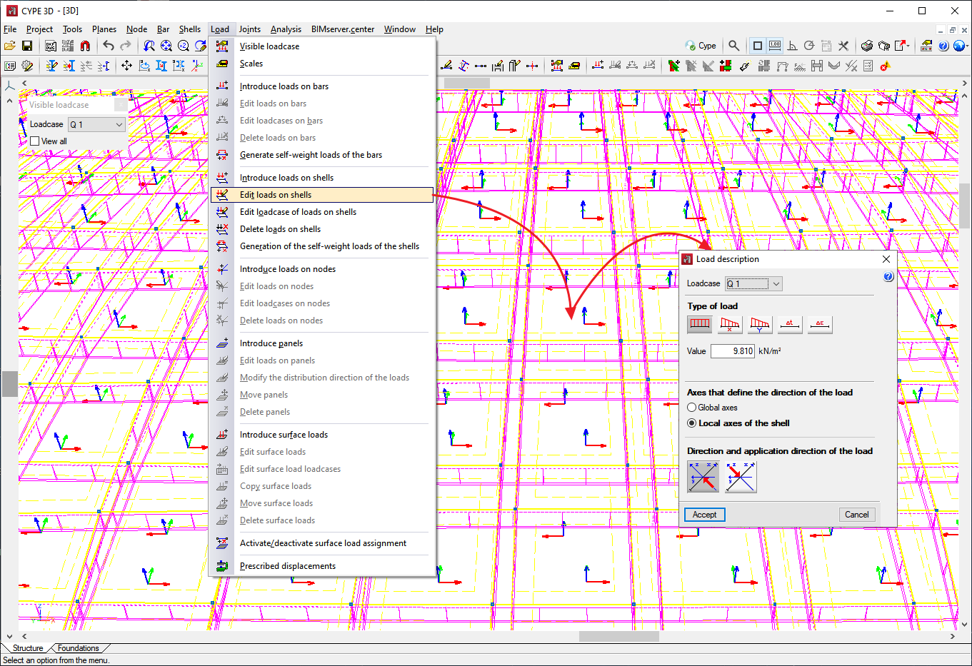
Defining loads
There are two ways of introducing loads on the shells. One is by using the options available in the "Loads" menu, which are identical to those available for bars or nodes. The other is to bring the shell into the area of a panel of loads.
In the first case, the loads that can be introduced are surface loads applied over the entire surface of the shell, their direction of application can be the global z-axis or the local z-axis of the shell.
In the second case, two restrictions must be taken into account:
- If a panel of loads contains a shell, the panel of loads must be completely covered by shells.
- If a shell is in contact with any of the surface loads of the panel the load must completely cover the shell. Under these conditions, the loads generated are again surface loads over the entire shell but whose direction and direction depend on those defined for the panel and the surface loads.
Checking forces
There are two ways to check the forces on a shell:
Checking forces in integration strips
Checking forces in integration bands is carried out as if it were just another bar using the options in the analysis menu that were already available in previous versions.
It should be noted that the integration strips in shells define lines over which, for the given width of a strip, the forces corresponding to the shell are integrated to obtain bar forces. The definition of the integration strips is available in the "Shells" menu.
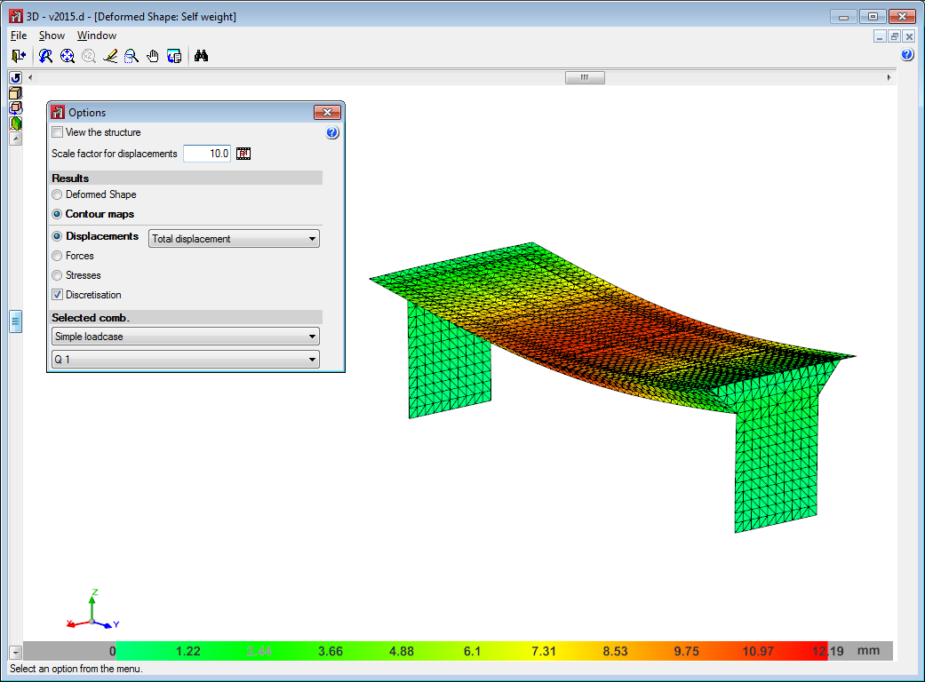
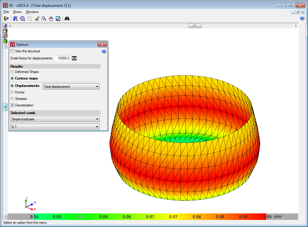
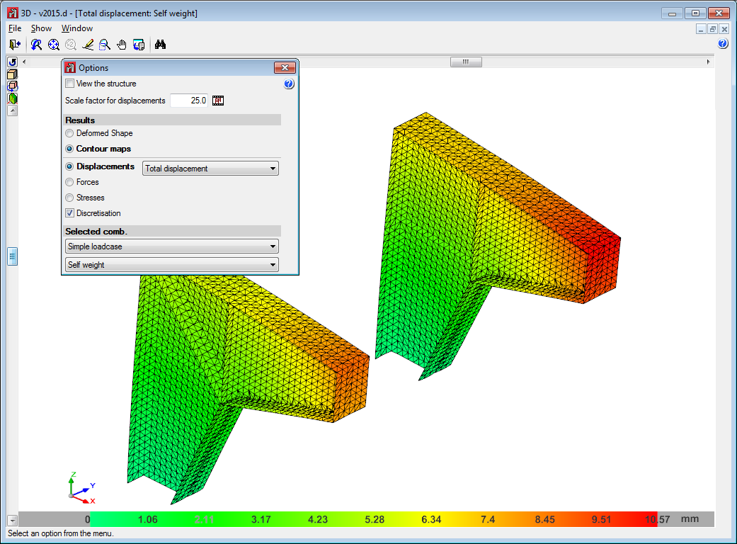
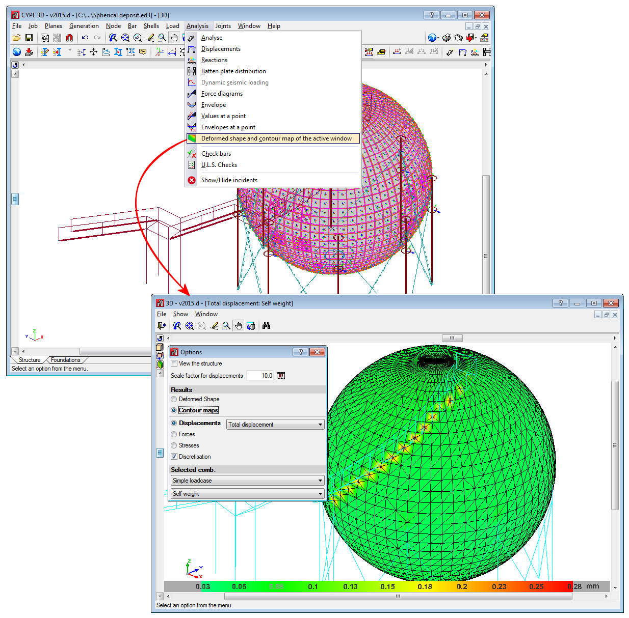
Viewing contour plots
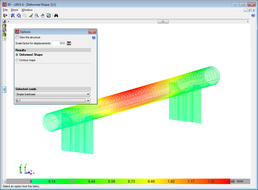
The “Deformed shape and contour plot of the active window” option has been implemented, which allows users to consult the deformed shape and contour plots of the elements visible in the window that is currently active. In this option, the following can be viewed:
- The deformed shape of the currently selected combination including all elements of the structure and their animation.
- The displacements of the shell elements by means of contour plots. The values that can be consulted are:
- Total displacement
- Displacement in global X, Y or Z axis
- Rotation about the global X, Y or Z axis
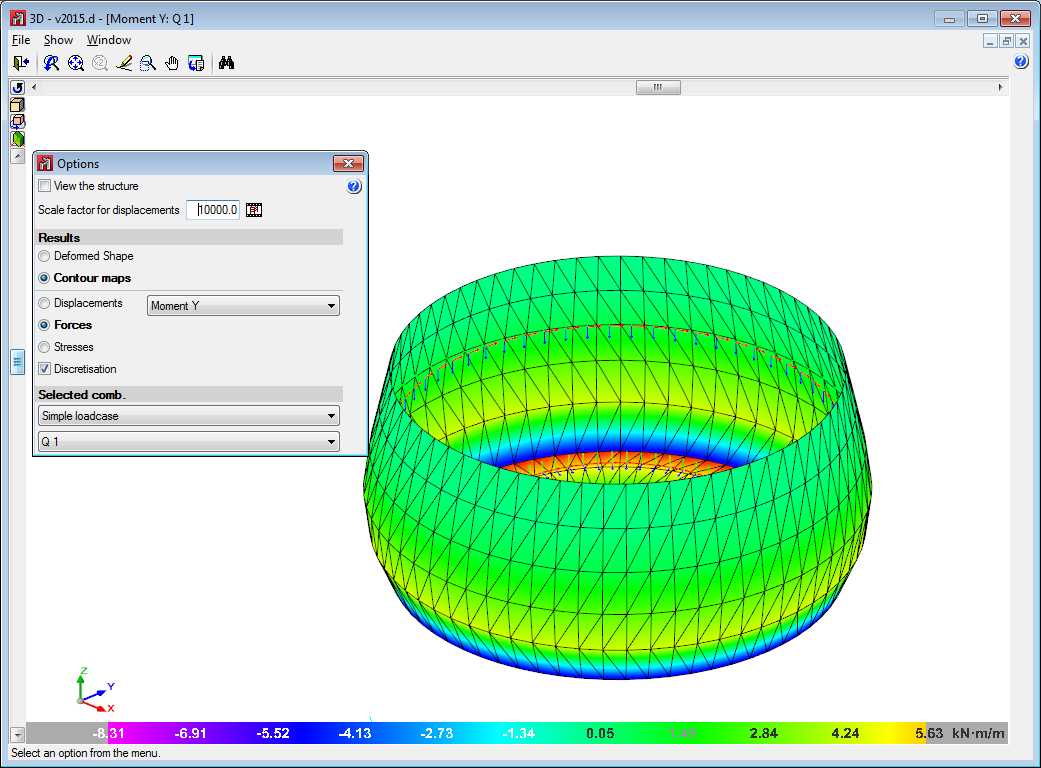
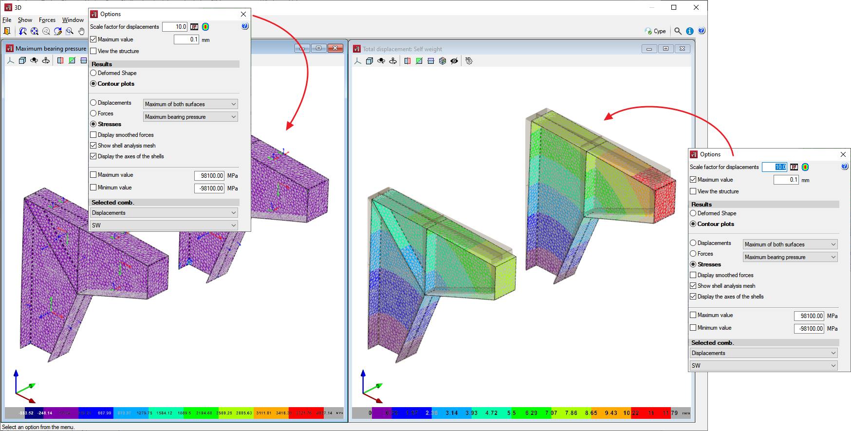
- The forces of the shell elements in local axes of the shell using contour plots.
- The stresses of the shell elements in local axes of the shell using contour plots. The following stresses can be viewed:
- Normal X
- Normal Y
- Shear XY
- Shear XZ
- Shear YZ
- Maximum normal stress
- Minimum normal stress
- Maximum shear stress
- These stresses can also be filtered by:
- Top face
- Bottom face
- Maximum of both surfaces
- Minimum of both surfaces
- Absolute maximum of both surfaces
By viewing contour plots, several windows can be kept open simultaneously with different information in each of them.
The configuration of the different contour plot windows is associated with each of the CYPE 3D structure views and is maintained even if the contour plot window is closed as long as the program is not closed.
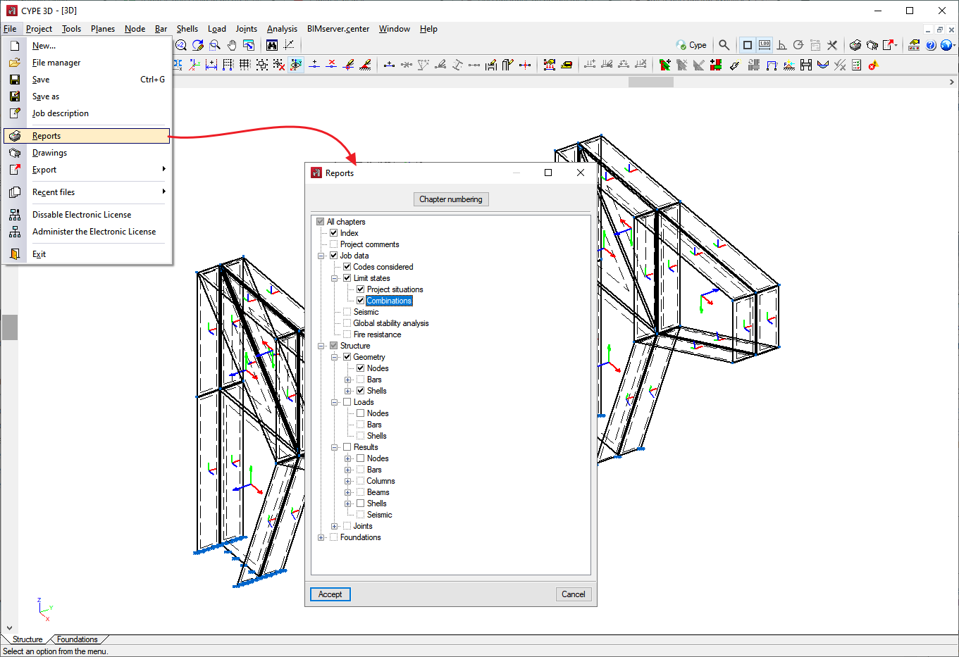
Reports
The reports that can be obtained in the program are as follows:
- Materials used
- Shell description
- Shell quantities by material
- Shell surface quantities by material
- Loads on shells
- Forces in integration strips by loadcase
- Forces in integration strips by combinations
- Forces in integration strips by envelopes