
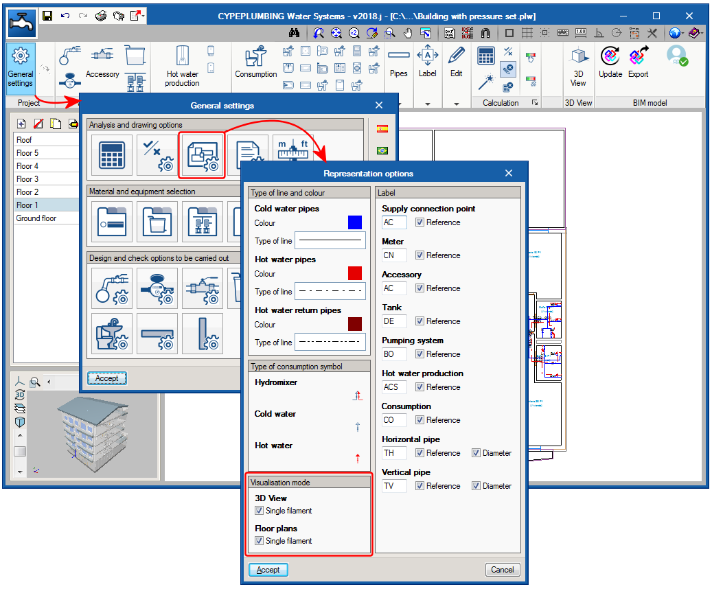
The 2018.j version of CYPEPLUMBING Water Systems includes two visualisation modes that affect the 2D and 3D views of the installation. For this, the “Visualisation mode” section has been added to the “Representation options” panel (General settings > Analysis and drawing options > Representation options). This section allows users to activate or deactivate the “Single filament” option for the 2D and 3D views separately. When activated, a single filament view is displayed, and when deactivated, a volumetric view can be seen. The properties of these views are detailed below:
- Single filament view
This is the view that was available as of previous versions and that which is active by default. With this view, the pipes of the installation a represented as a line on drawings, and in the 2D and 3D on-screen views. - Volumetric view
The pipes of the installation are represented in their real magnitude on drawings and in the 2D and 3D views.
In the 3D views, the remaining elements of the installation do not vary when either view is selected, and are represented with a volume surrounding their real appearance.
In the 2D views, pressure sets, tanks and hot water production equipment are represented with their symbols in the “Single filament visualisation” (which may or may not coincide with their real appearance). In the “Volumetric view”, these elements are represented with their symbols and also with their real outline.
When the pipes are exported to the BIM model, these are exported as single filament elements, if the single filament option of the 3D view is activated or as volumetric elements if it is not.