Starting with the 2025.a version of CYPE programs, the following applications will no longer be available:
- CYPEPLUMBING Water Systems and CYPEPLUMBING Sanitary Systems
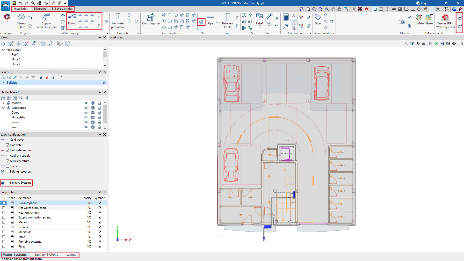
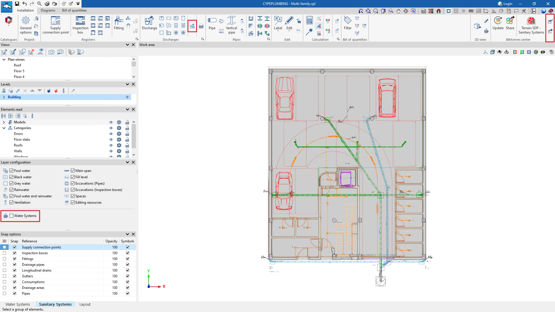
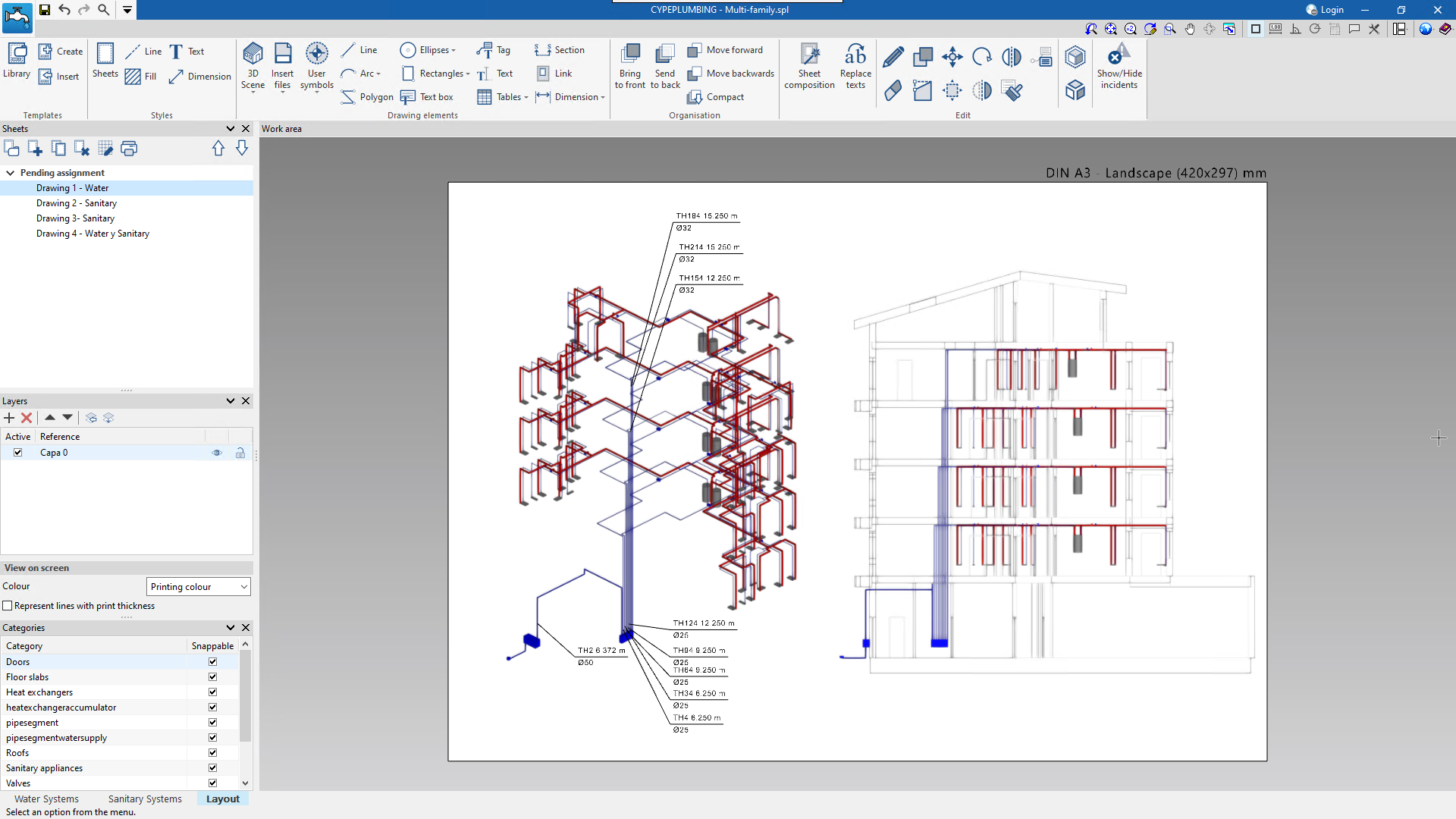
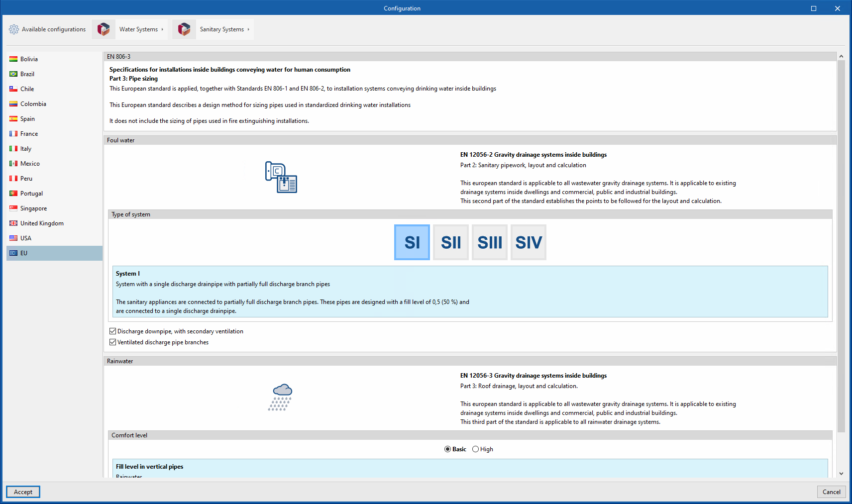
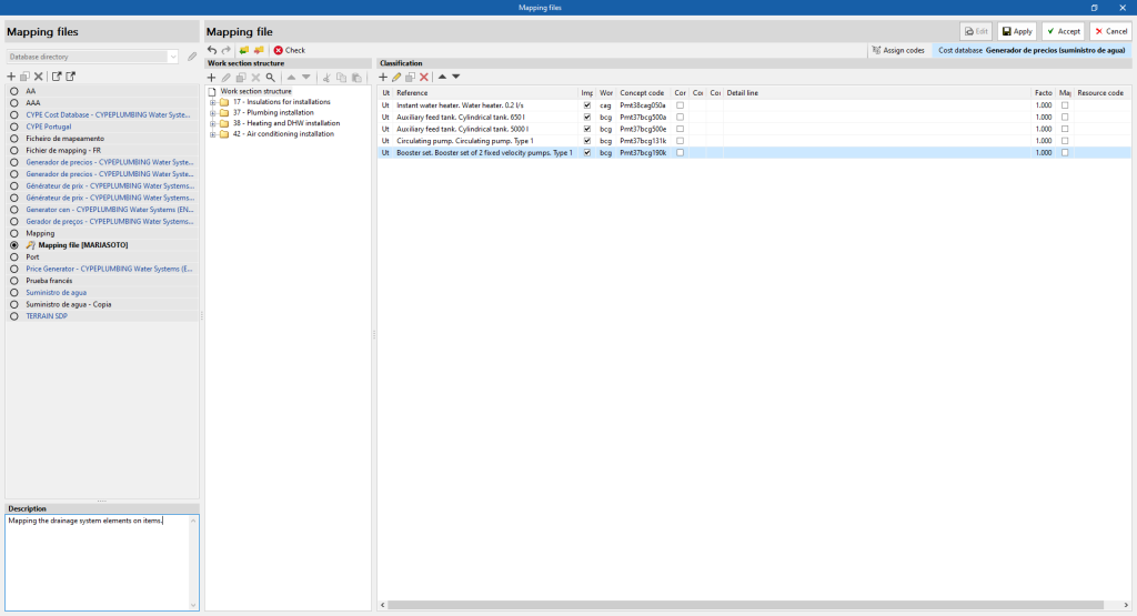
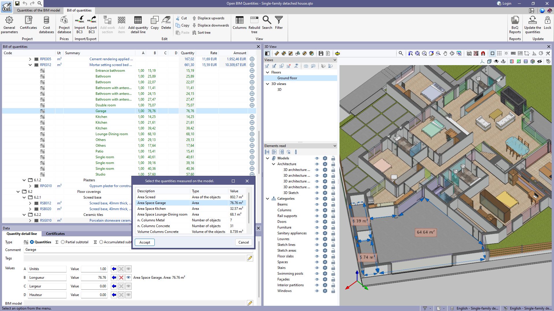
The features of these two programs are combined in CYPEPLUMBING (new application implemented in version 2025.a). Users can now design water supply systems, wastewater and rainwater drainage systems and create their drawings in the same program. Learn more about the advantages of this new application implemented in version 2025.a in CYPEPLUMBING.
Version 2024.f of CYPEPLUMBING Water Systems and CYPEPLUMBING Sanitary Systems can still be downloaded from the BIMserver.center platform. - CYPEPLUMBING Schematics diagrams
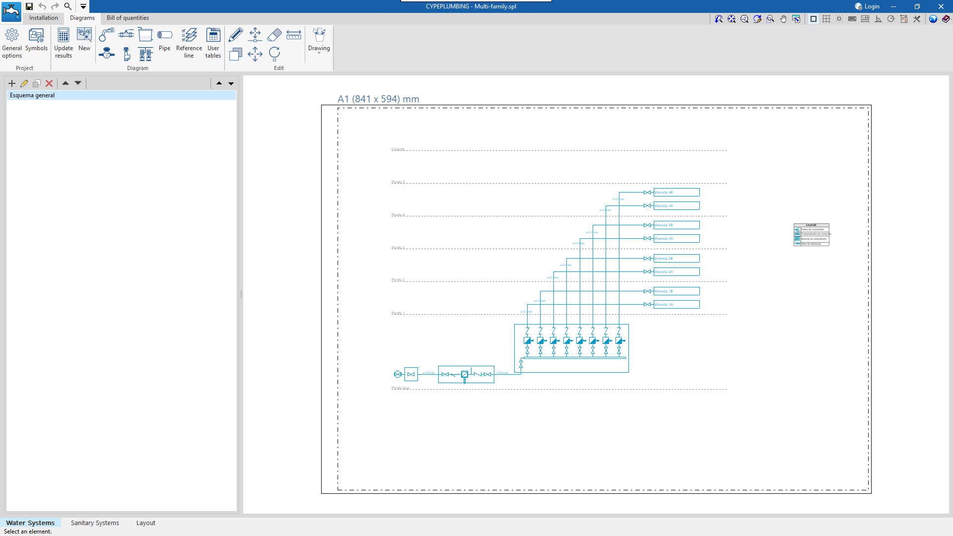
The features of this application (automatic generation of the schematic diagram of a water supply system using the BIM connection with CYPEPLUMBING Water Systems) become part of CYPEPLUMBING in version 2025.a; and can be found in the main CYPEPLUMBING window, specifically, in the "Diagrams" tab located at the top and which appears when the "Water Systems" tab located at the bottom is selected. In CYPEPLUMBING you can find out about the advantages of this new application implemented in this version 2025.a.
Version 2024.f of CYPEPLUMBING Schematics diagrams can still be downloaded from the BIMserver.center platform. - CYPEPLUMBING Solar Systems
This application will no longer be generated in version 2025.a. However, the CYPEPLUMBING Solar Systems download version 2024.f is still available on the BIMserver.center Store so that users can continue to design solar thermal systems for domestic hot water or heating. In versions after 2025.a, the features of this program will become part of CYPEPLUMBING. - Open BIM Water Equipment
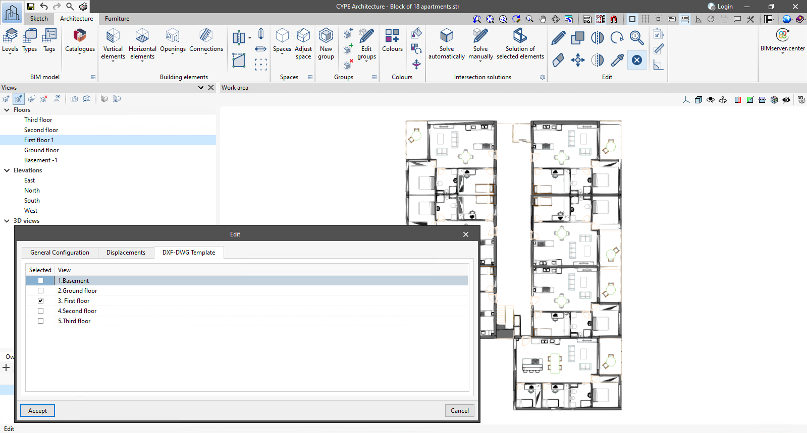
The equipment that could be entered by this application can continue to be entered from CYPE Architecture, and the consumption and discharge values of each unit are automatically entered in CYPEPLUMBING when a consumption or discharge system is positioned.