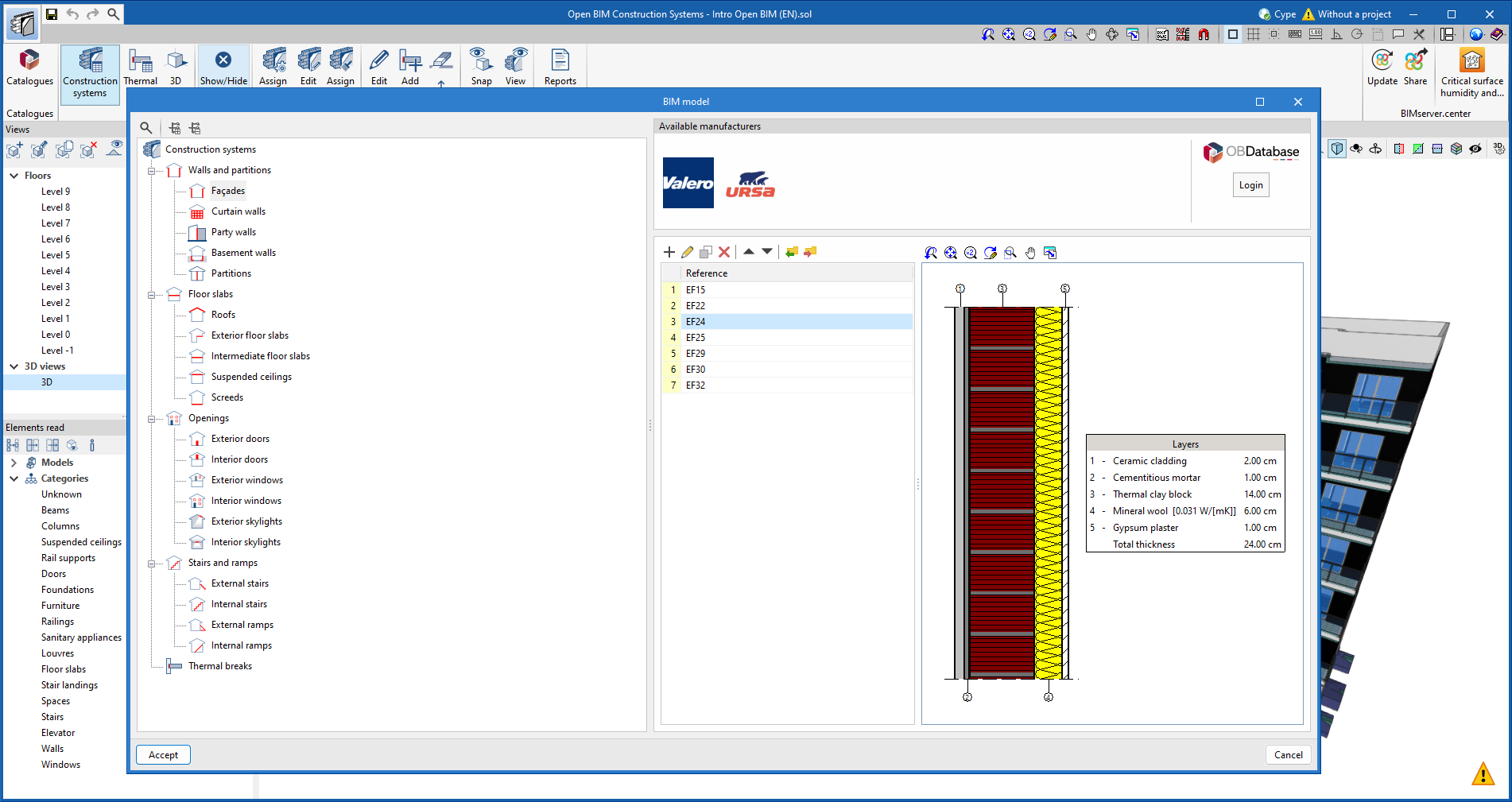
As of version 2024.c, the types of construction systems are sorted into a tree diagram and are grouped in the following sections:
- Walls and partitions
- Floor slabs
- Openings
- Stairs and ramps
- Thermal breaks
As of version 2024.c, the types of construction systems are sorted into a tree diagram and are grouped in the following sections:
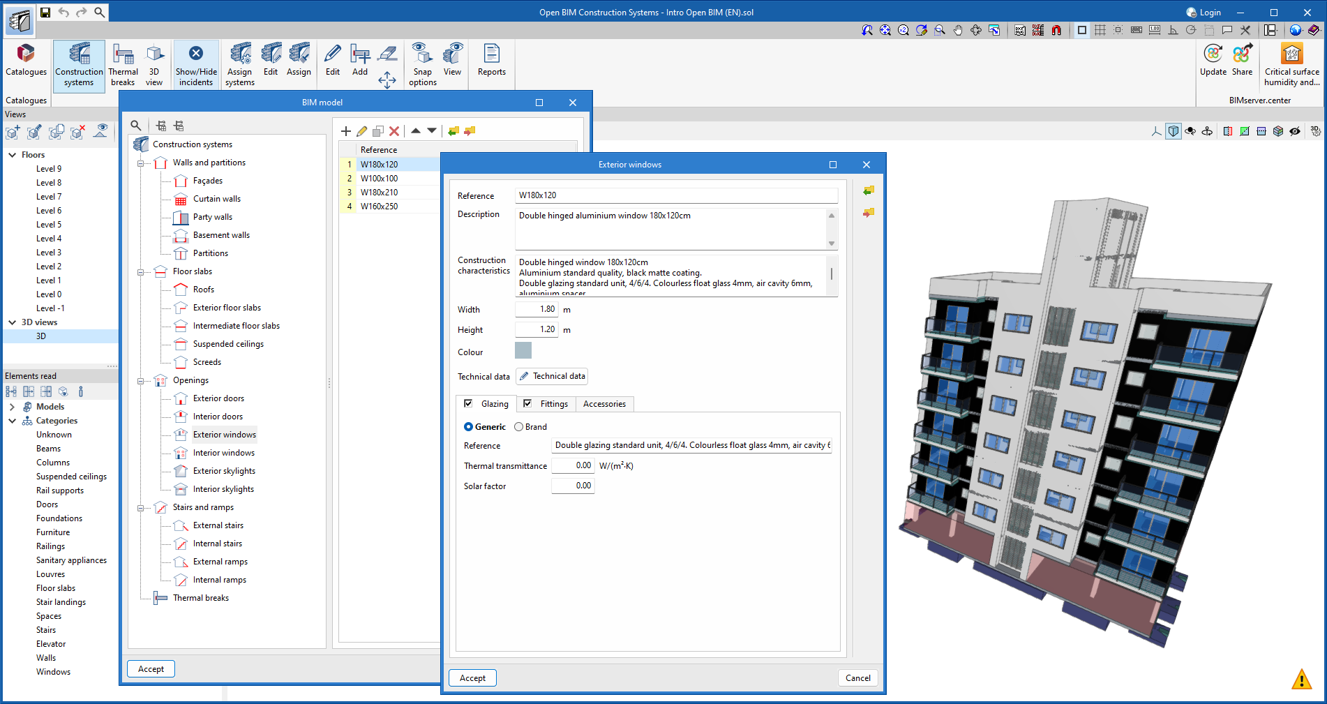
The following changes have been made to the definition of windows, doors and skylights:
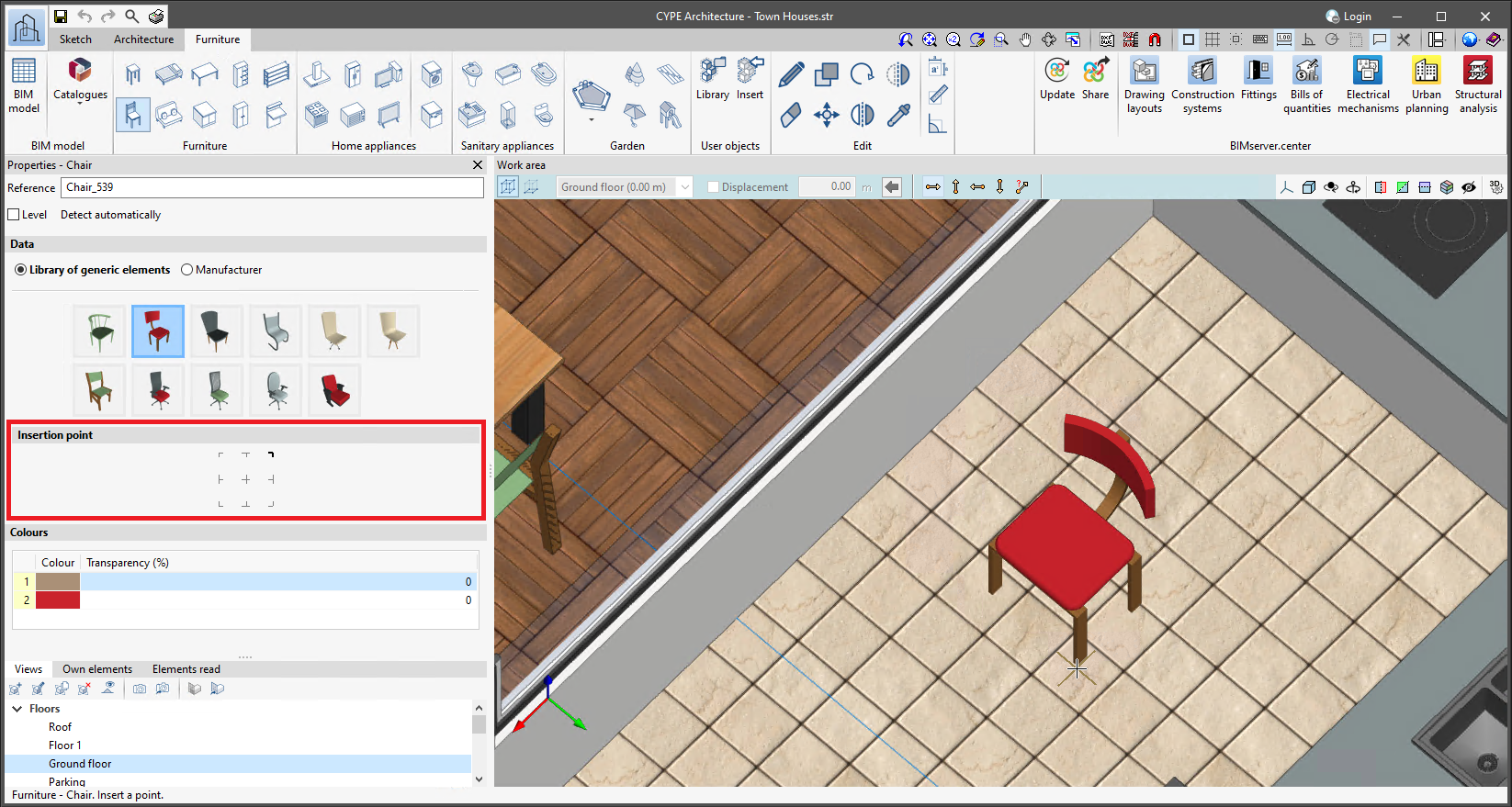
Version 2024.c includes two improvements concerning the insertion point:
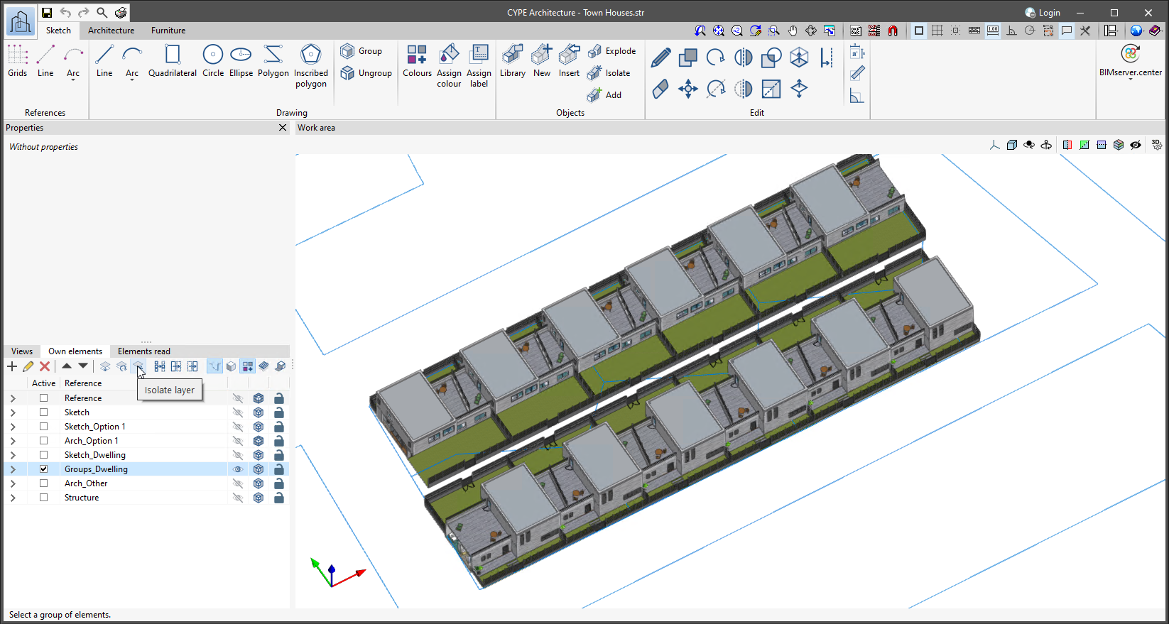
The "Isolate layer" option has been implemented in the "Own elements" section. This option allows users to isolate the active layer, turning off the rest of the layers available in the project.
To turn all the layers of the project back on, simply click on the visibility column of the project's own elements and select "Show all".
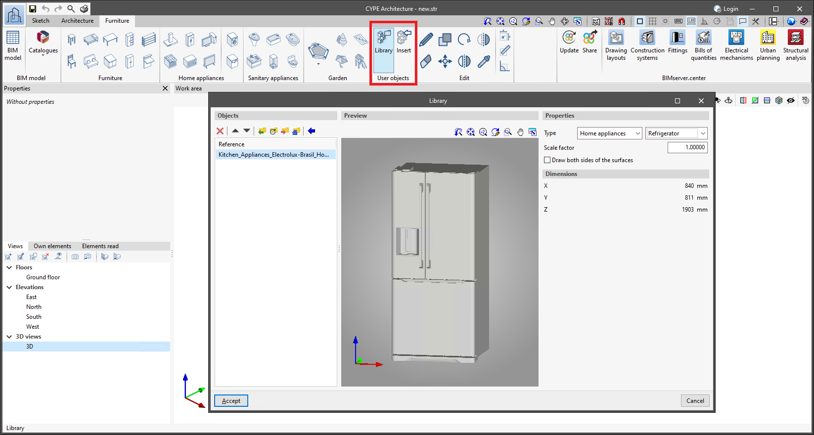
CYPE Architecture allows users to import furniture objects and create their own library. The library allows objects to be imported in ".ifc", ".obj" and ".step" formats.
In the "Furniture" tab, there is now a new "User objects" section with two options:
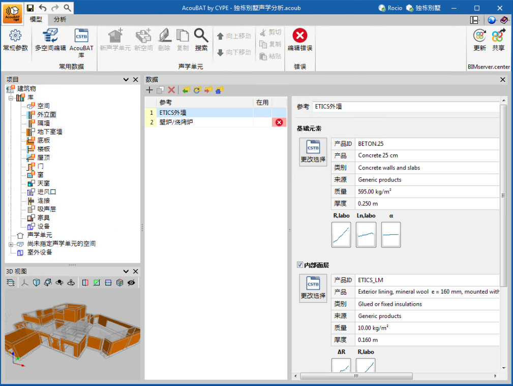
As of version 2024.c, AcouBAT by CYPE can also be installed in Chinese. The languages this application can now be installed in are as follows:
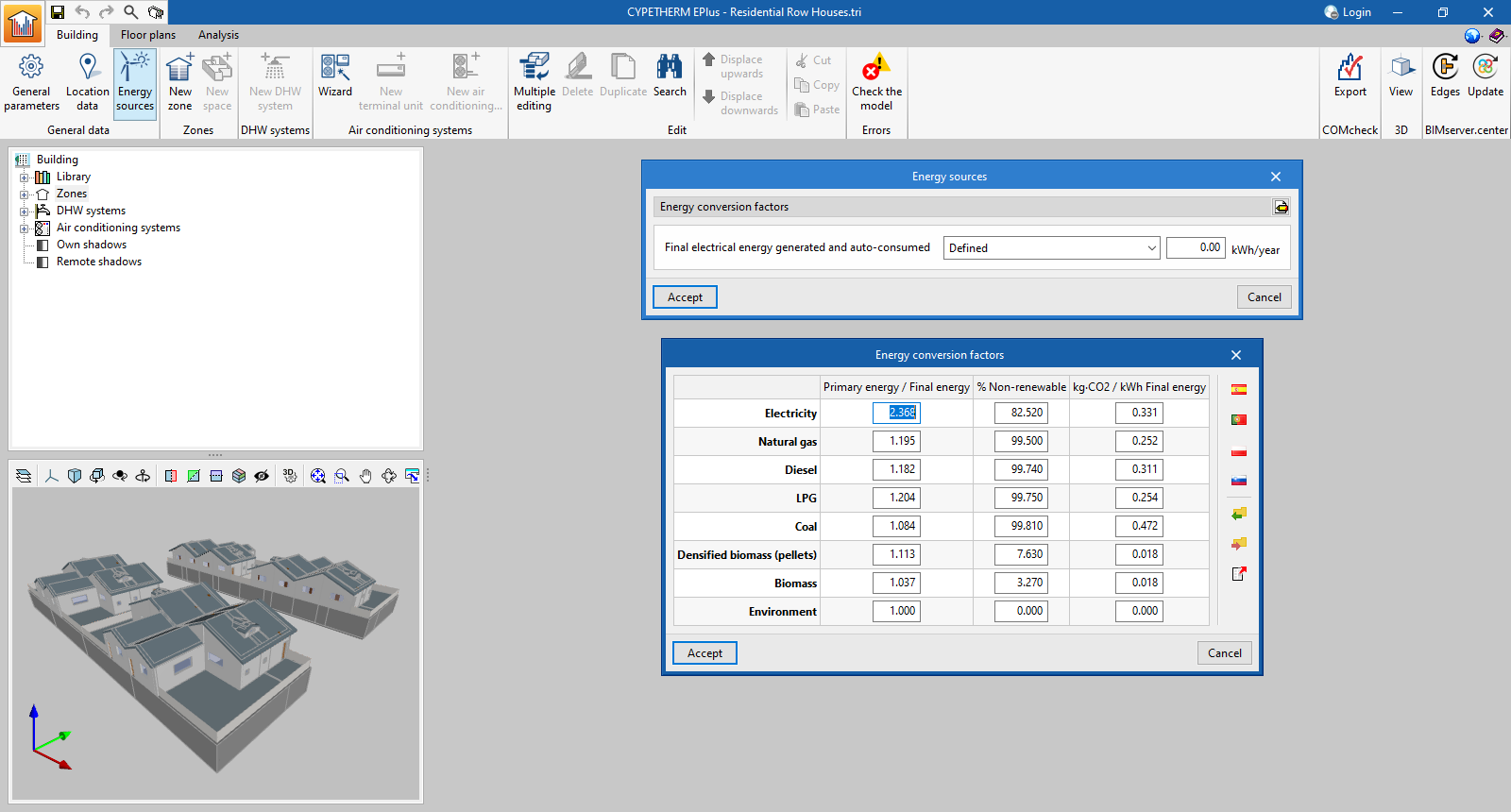
In the "Energy Sources" option, in the "Energy conversion factors" section, assistants have been added to load the national values for Spain, Portugal, Poland and Slovenia. Furthermore, users can import and export the values defined in this section in order to reuse them in other projects.
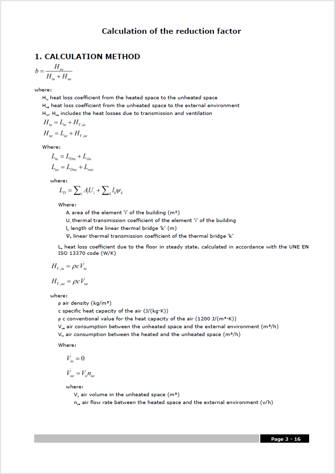
Within the "Complementary reports", we have added the "Calculation of the reduction factor (b)" report, which contains the methodology and detailed results from the calculation of the heat transfer to the unconditioned spaces of the building in accordance with EN ISO 13789:2017.
The results provided in this new report are used in the calculation of the heat transfer coefficient of the building envelope report.
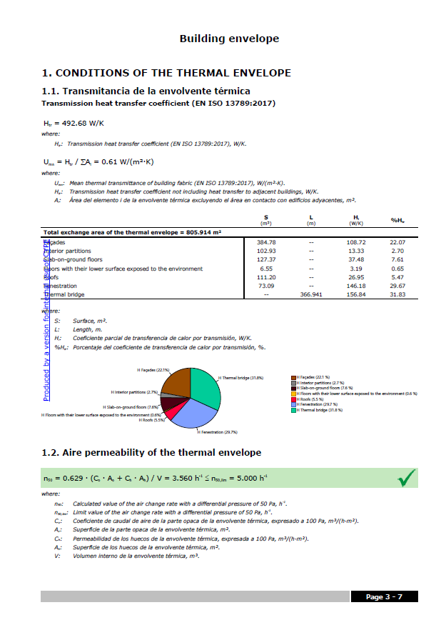
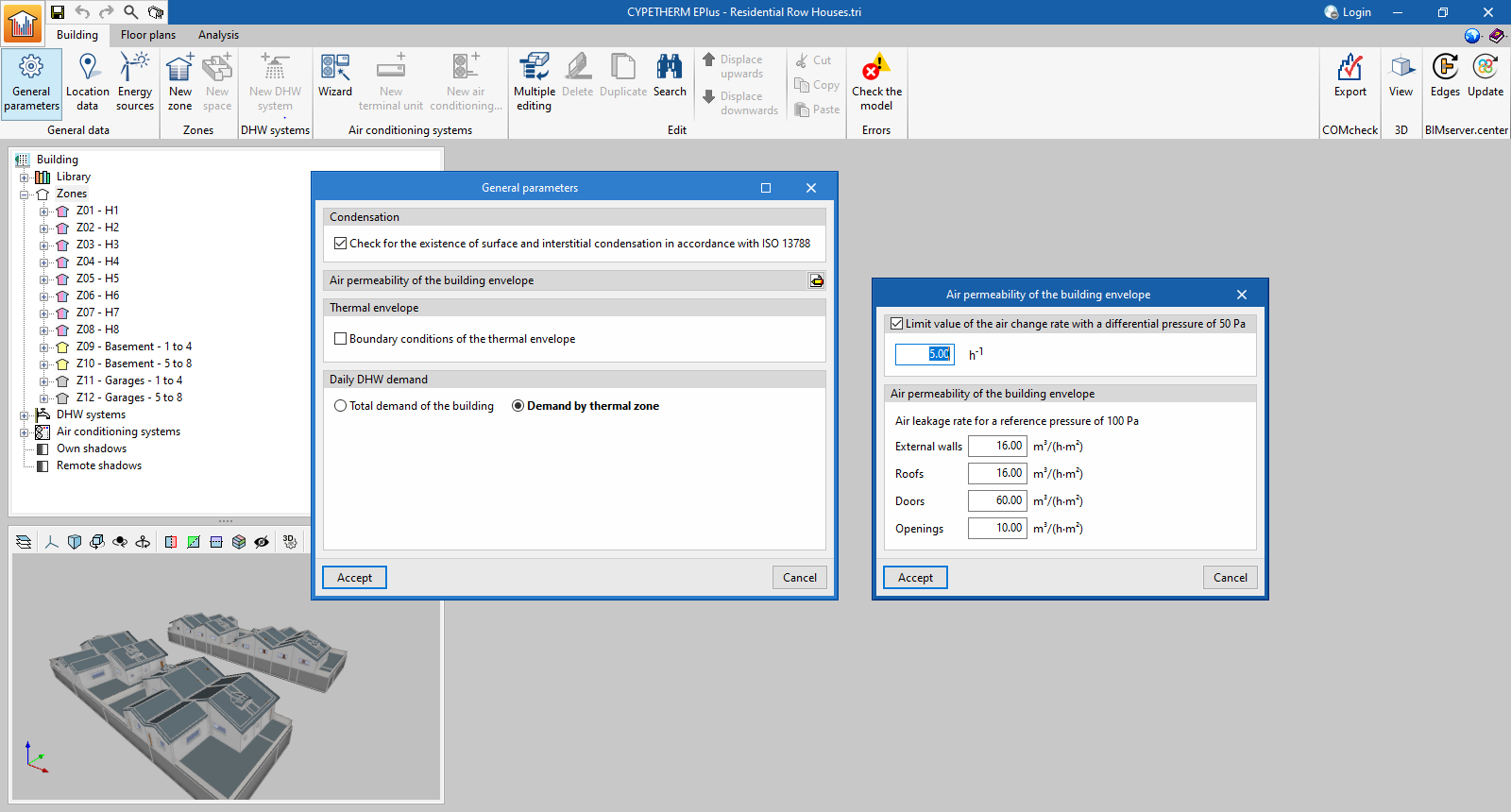
The results output of the program has been enhanced with the new "Building envelope" report, available in the toolbar of the "Analysis" tab. This new report, which can be accessed without having to analyse the model, provides the results of the transmission heat transfer coefficient calculated according to EN ISO 13789:2017 and the air permeability of the thermal envelope. A breakdown by elements is provided and the thermal transmittance (U) value of each element is compared with the limit value set by the user.
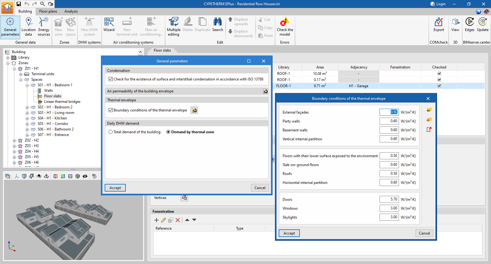
The limit transmittance values for each type of building element can be set in the "Building" tab, under "General parameters", where the new "Thermal envelope" section appears. By activating the "Boundary conditions of the thermal envelope" checkbox, the program will check the limit transmittance of the building elements both in the "Check" button of the model and in the new "Building envelope" report.
Also, in the "Air permeability of the building envelope" section, users can now define a "Limit value of the air change rate with a differential pressure of 50 Pa", which will also be checked in the new report.
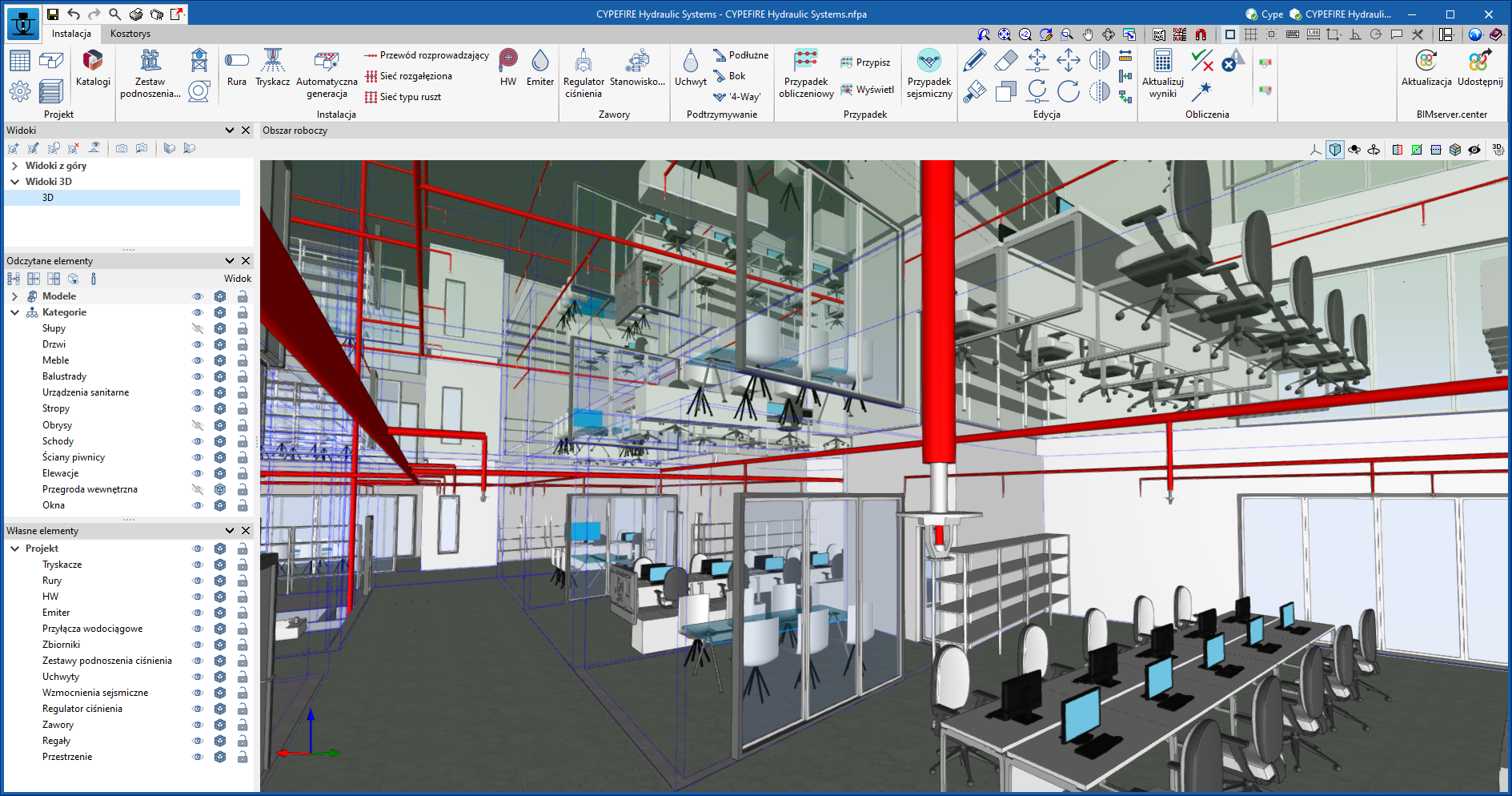
As of version 2024.c, CYPEFIRE Hydraulic Systems can also be installed in Polish. The languages in which you can install this application are now as follows:
As of version 2024.c, CYPECAD now allows users to include electrowelded mesh for use in the analysis of flat slabs in a similar way to the use of the base reinforcement. As well as designing the reinforcement taking into account the electrowelded mesh, the program also allows users to detail the reinforcement, obtain reports and drawings as well as detailed measurements of the reinforcement.
Electrowelded meshes are part of a new CYPECAD module, so in order to use them, users must have the corresponding permission in their user license.
Electrowelded mesh and base reinforcement
For analysis purposes, the electrowelded mesh and the base reinforcement are treated in the same way, bearing in mind that, when designing the slab reinforcement, both elements provide a uniform mechanical ratio throughout the slab.
For flat slabs, the program now allows users to choose between assigning base reinforcement or electrowelded mesh.
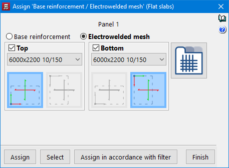
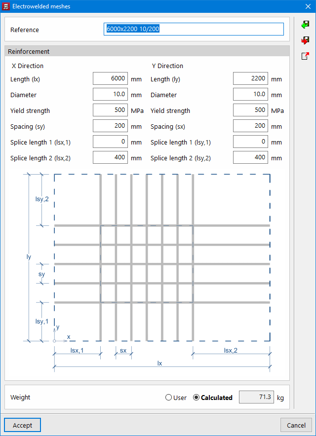
When selecting the "Electrowelded meshes" option, the program allows users to choose from all the references defined in the library. New meshes can be added to the library by defining their reference and characteristics.
The X and Y axes of the mesh can be made to coincide with the reinforcement axes of the slab, or they can be rotated by 90°.
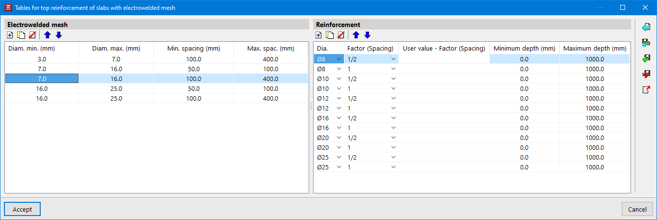
The program designs the necessary reinforcement bars in addition to the mesh, using the reinforcement tables for slabs with electrowelded mesh.
Editing electrowelded meshes
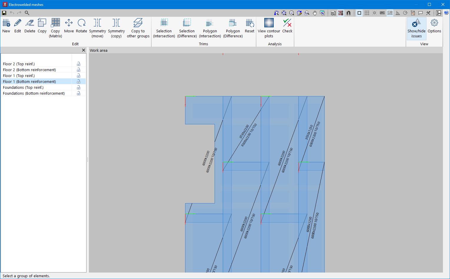
If meshes have been assigned to any of the panels, the "Electrowelded meshes" option will be activated in the "Flat/Waffle slabs" menu in the "Results" tab. After analysing the job, the program will automatically generate a mesh distribution proposal for the top and bottom reinforcement of the flat slab sections, which can be checked and modified using this option (Electrowelded meshes). The editor allows users to delete, move and trim the existing meshes. It also includes different features to make it easier to enter new mesh in the desired areas.
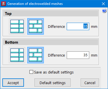
The criteria for automatically generating the mesh distribution can be configured in the menu "Job" > "Floor slab options" > "Generation of electrowelded meshes".
The layout of the electrowelded meshes should ensure that the floor slab panel is completely covered by the mesh panels, taking into account that each panel should overlap with the next one in the overlapping area.
Electrowelded meshes report
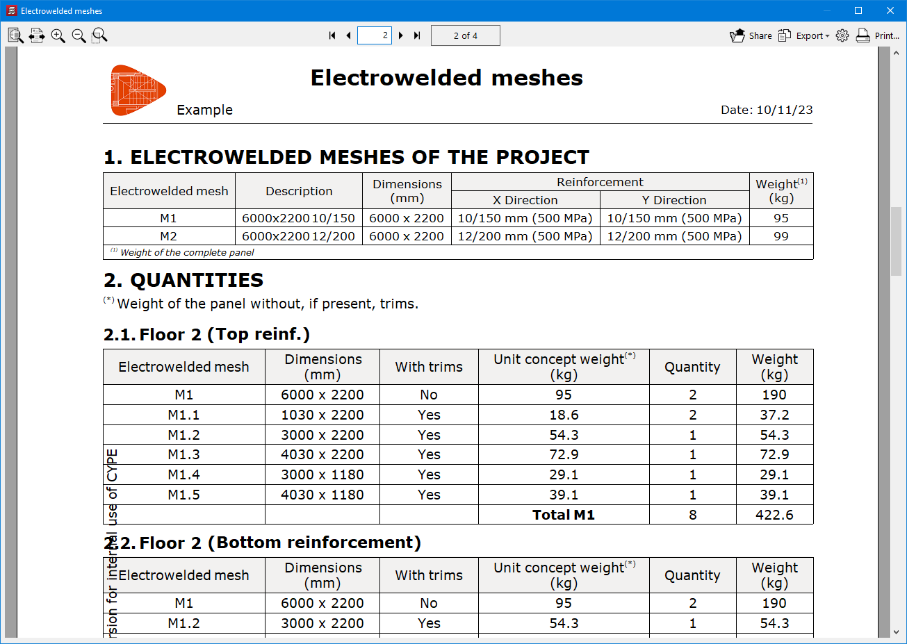
The "Reports" menu of the program includes the new "Electrowelded meshes" report, which contains information on the types of mesh used in the job as well as their characteristics and the quantity of panels per floor, taking into account, where appropriate, the necessary trimming to adapt them to the geometry of the floor slab.
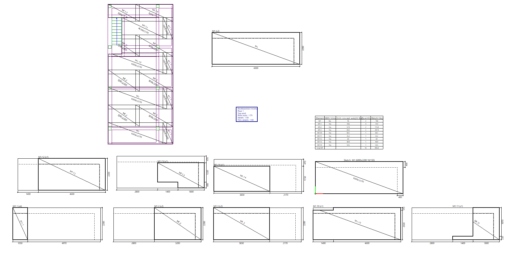
Electrowelded meshes drawing
The "Drawings" menu of the program includes the new "Electrowelded mesh" type of drawing. As with other CYPECAD floor plans, the elements to be shown can be configured in this drawing by means of a series of options.
The drawing shows a floor with the layout of the electrowelded meshes, a detailed model of the different meshes used in the job, and details of each of the trimmed panels. A summary table with the quantities and weights of each of the elements in the drawing is also included.
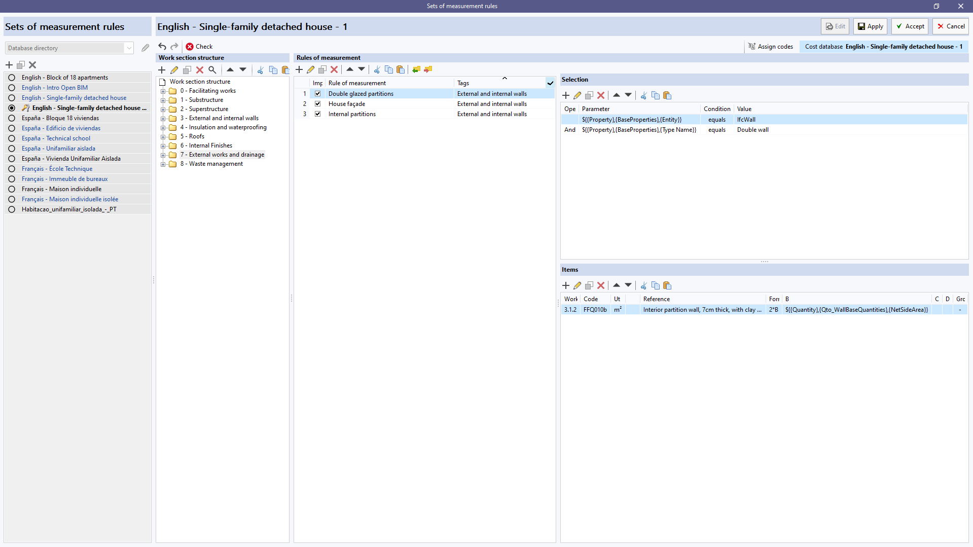
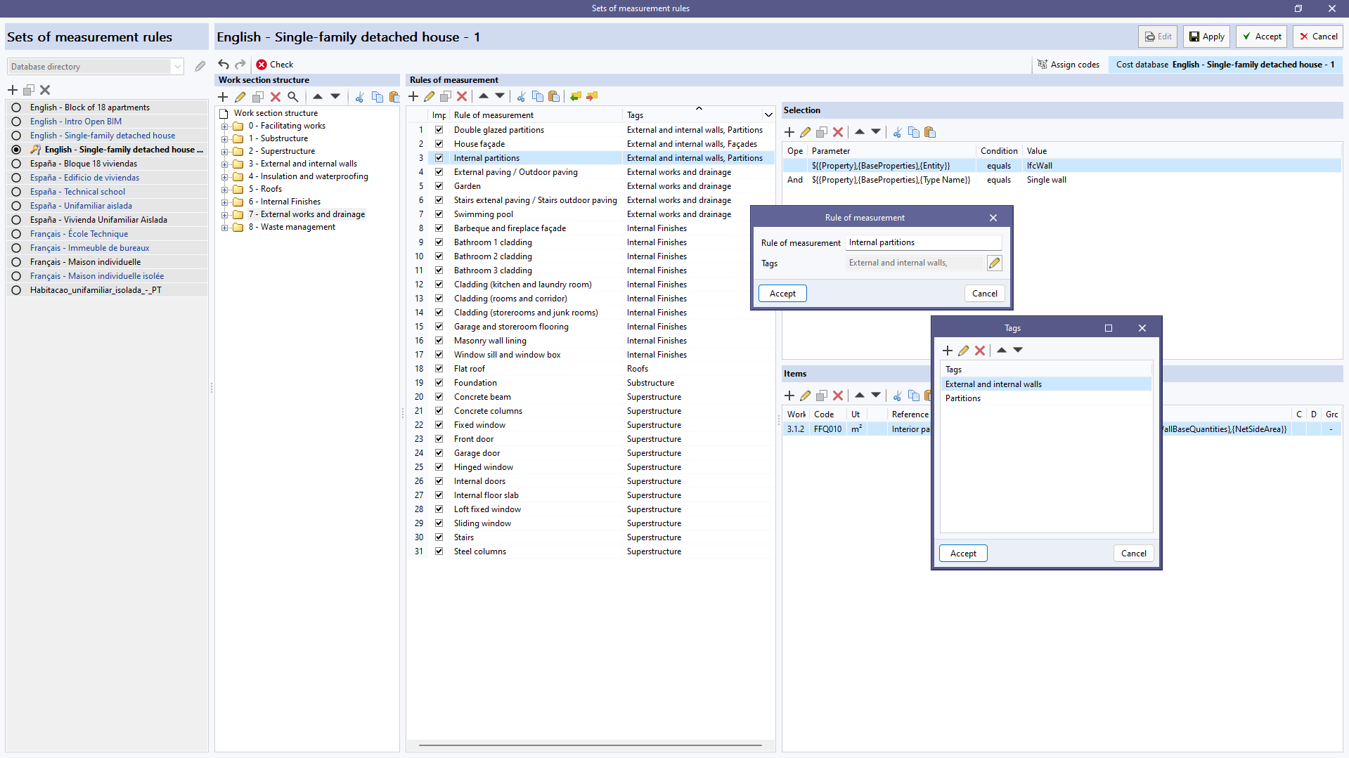
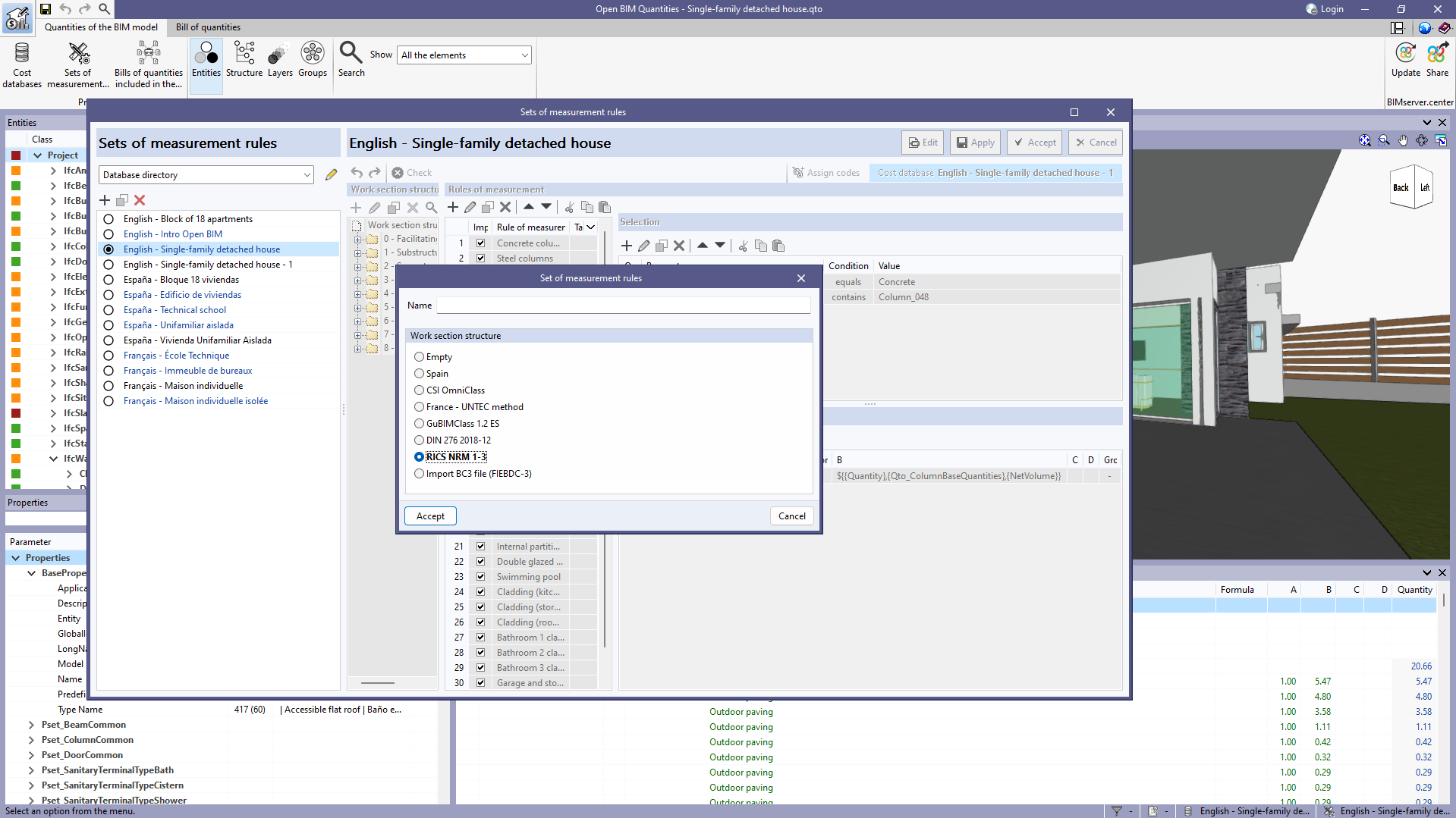
As of version 2024.c, tags can now be associated with the rules of measurement defined within a "Set of measurement rules". When editing the reference of a rule, the "Tags" field now appears, allowing several independent text strings to be inserted. In order to make it easier to enter tags, when adding or modifying a tag, a button appears, with a blue arrow icon, which launches a list of the tags defined so far.
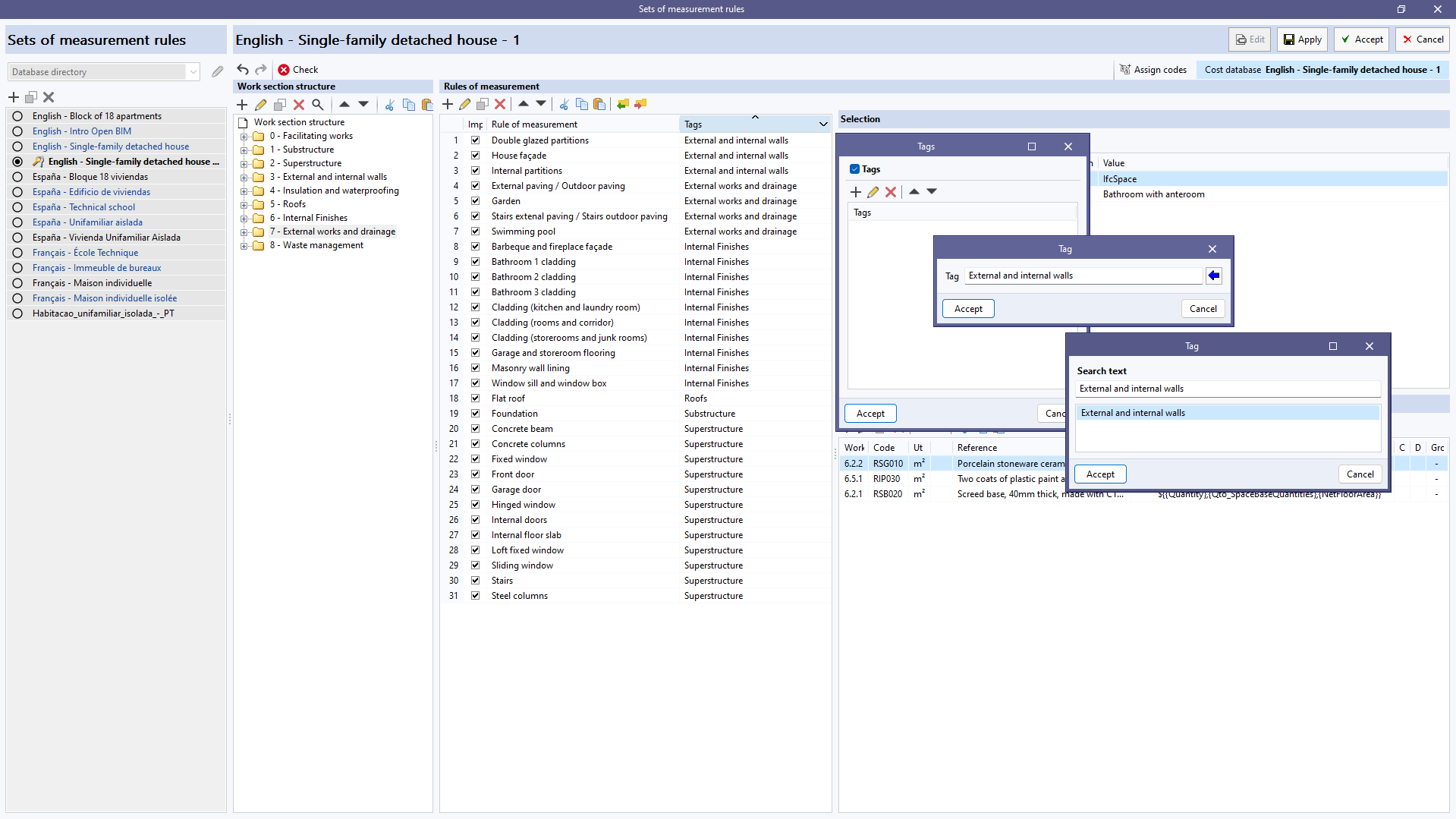
In the list of rules of measurement, a "Tags" column has been added which not only shows the tags linked to each rule but also allows the elements that appear in the list to be filtered. To do this, a button has been added to the column header. Clicking on this button displays a window where a list of tags can be specified. When accepting the window, only the rules that contain the entered tags will be displayed. This makes it easier to manage rules when there are a large number of rules in the project.
New predefined work section structures have been added for creating a new "Set of measurement rules" (in Open BIM Quantities) or a "Mapping file" (in applications with a "Bill of quantities" tab):
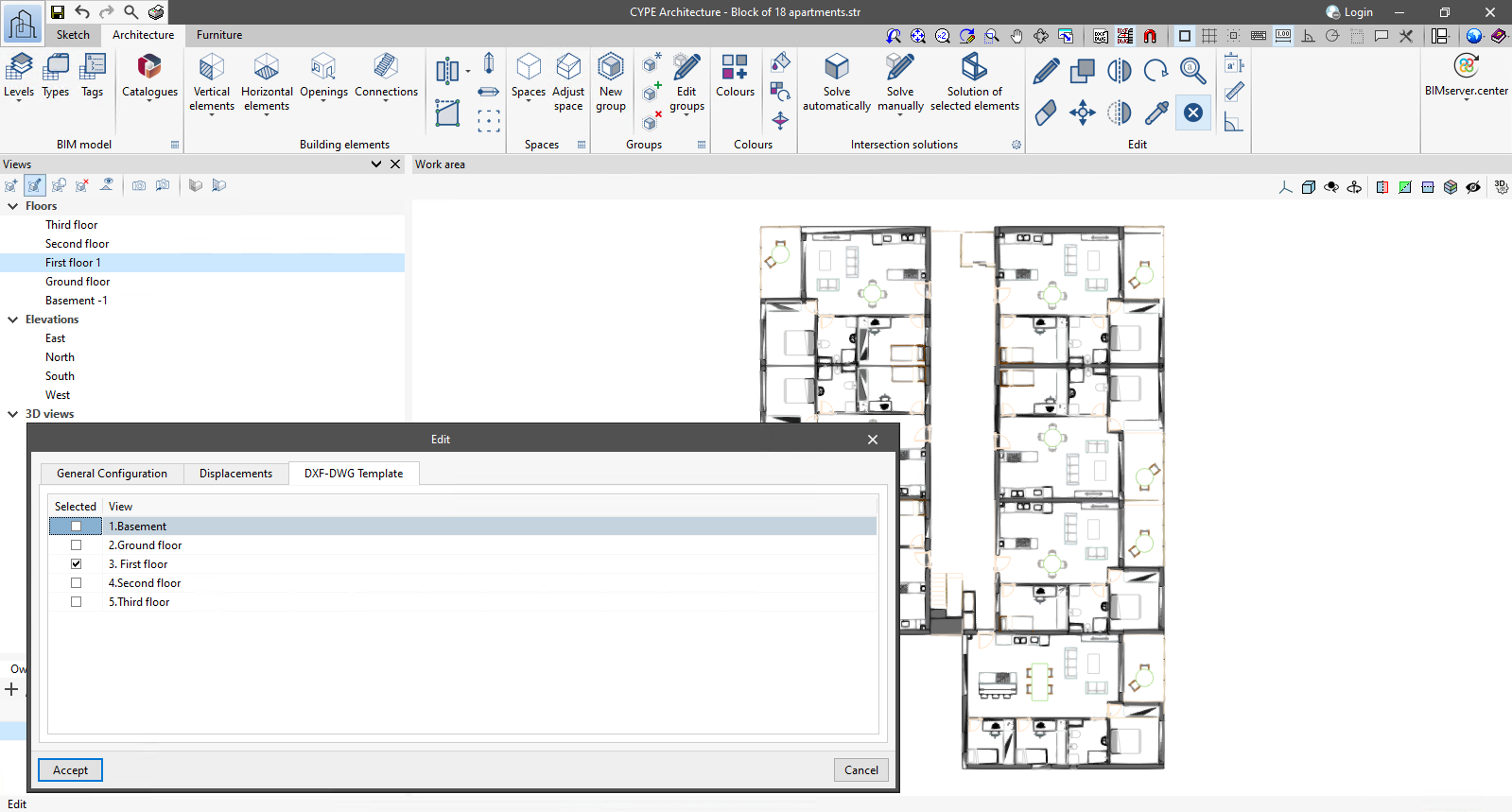
For 3D views defined within applications with a 3D working environment, the "Show selected templates in each floor view" option has been added. When activated, the templates visible in each of the floor views will be displayed in the 3D view in the dimension corresponding to these views.
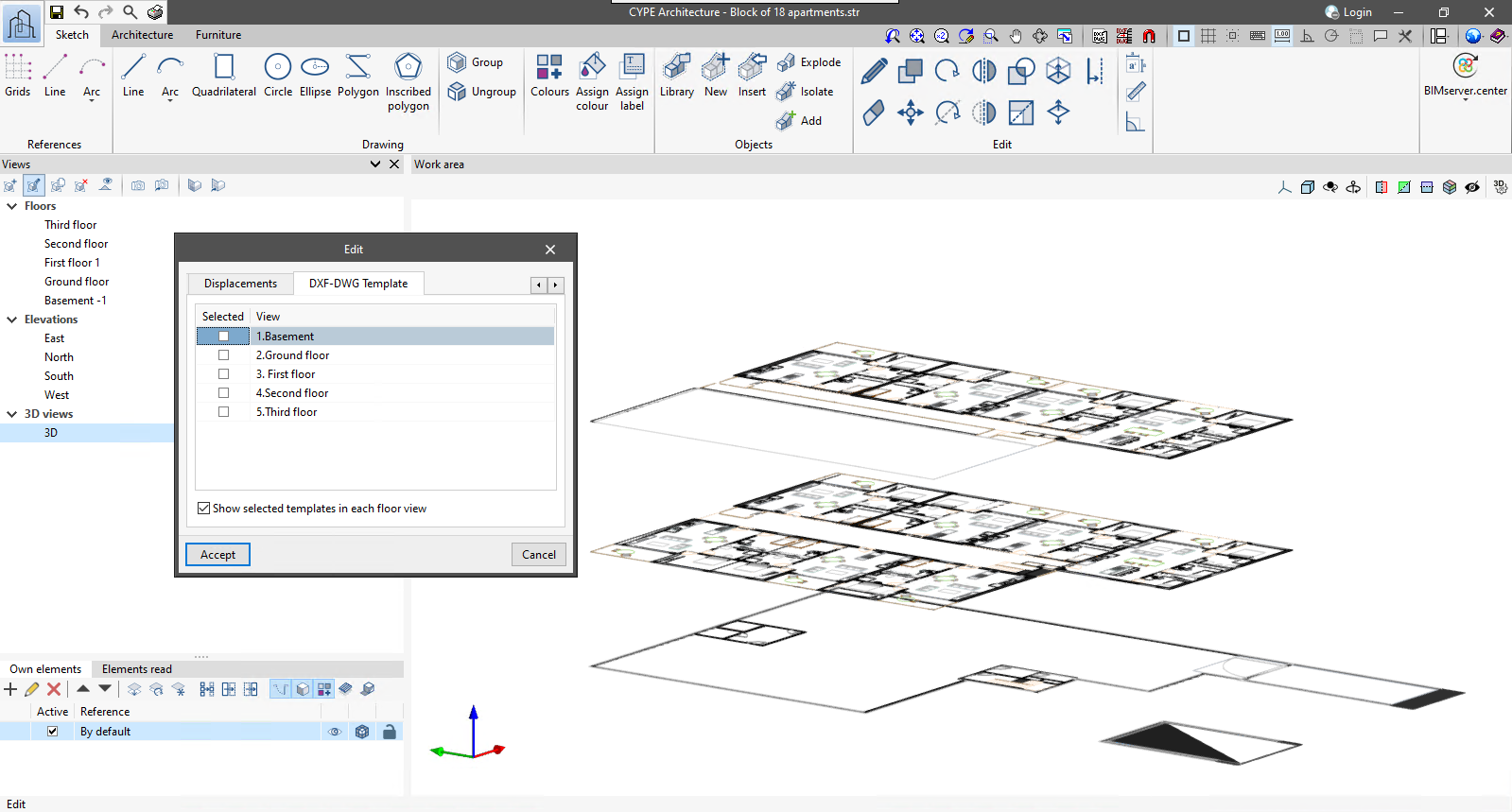
As of version 2024.c, applications with a 3D working environment can manage the visibility of templates from the view configuration panel. For this purpose, the "DXF-DWG templates" tab has been added, where a list of all the templates imported into the project is displayed together with a checkbox to indicate which ones should be shown in the view.
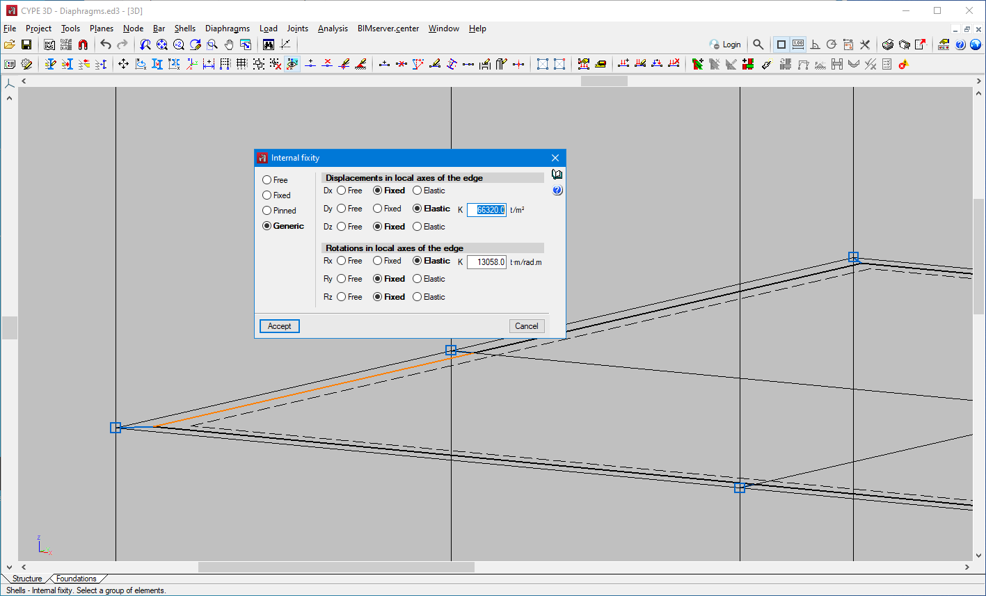
As of version 2024.c, the new "Generic" option has been added to the internal fixity of shells. This option allows you to define fixed, free or elastic displacements and rotations in local axes of the selected edge.
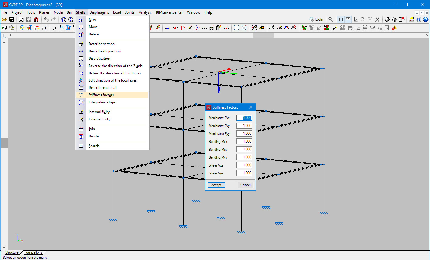
In version 2024.c the editing of the stiffness multiplying factors for the stiffness of the shells is implemented in CYPE 3D. The factors are assigned to a selection of shells.
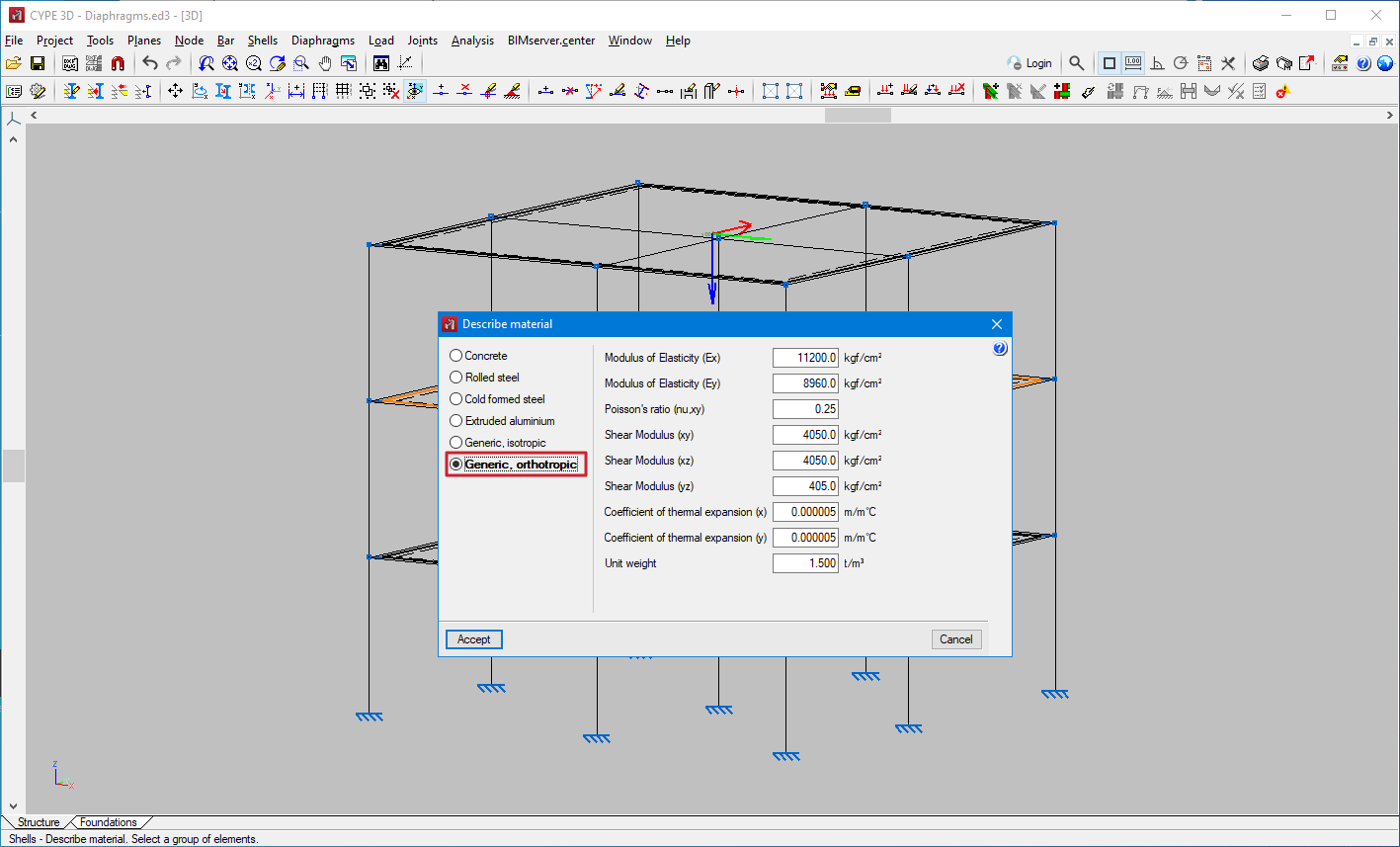
In version 2024.c the orthotropic material for shells is implemented in CYPE 3D. This material, for example, is of interest for the analysis of structures with cross-laminated timber panels.
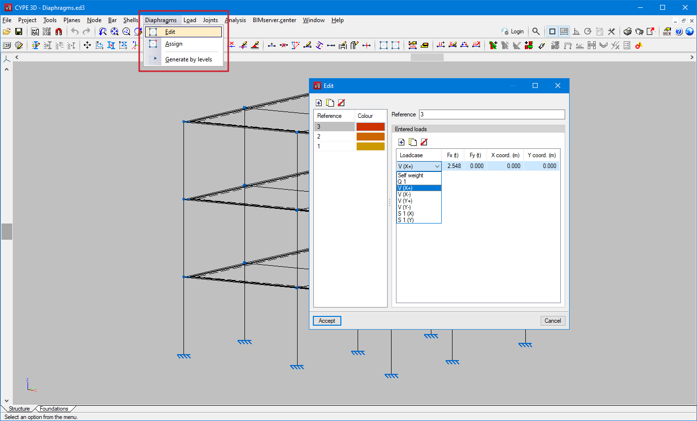
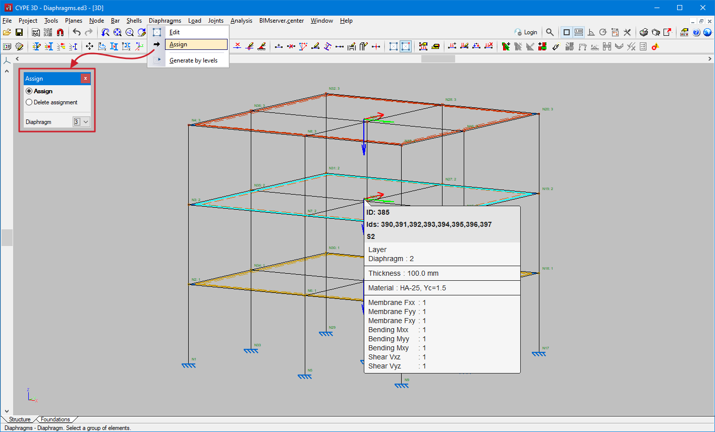
In version 2024.c rigid diaphragms have been implemented in CYPE 3D. The relative displacements between nodes belonging to the same rigid diaphragm are restricted. Therefore, each diaphragm can only rotate and move as a whole.
In the "Diaphragms" menu the following options can be found:
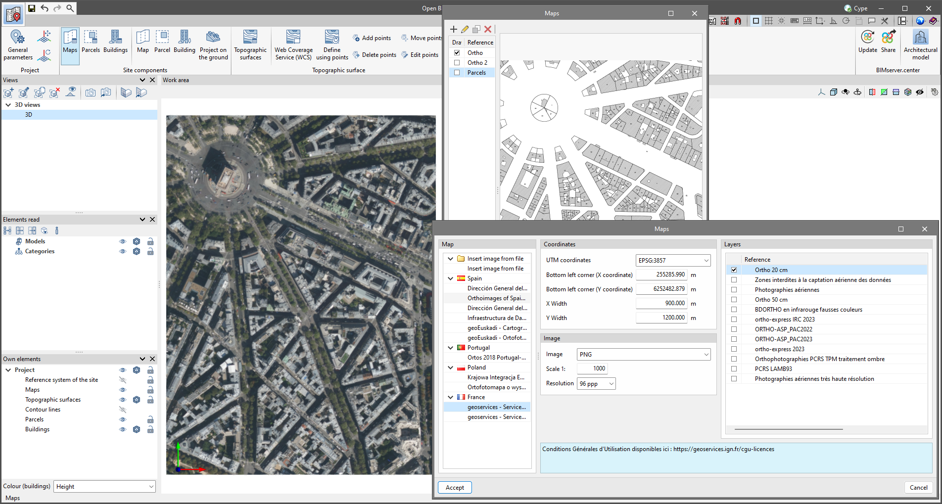
As of version 2024.c, Open BIM Site allows maps to be obtained through WMS services from the following data sources:
The following changes have been made to the layout of the application toolbar buttons:
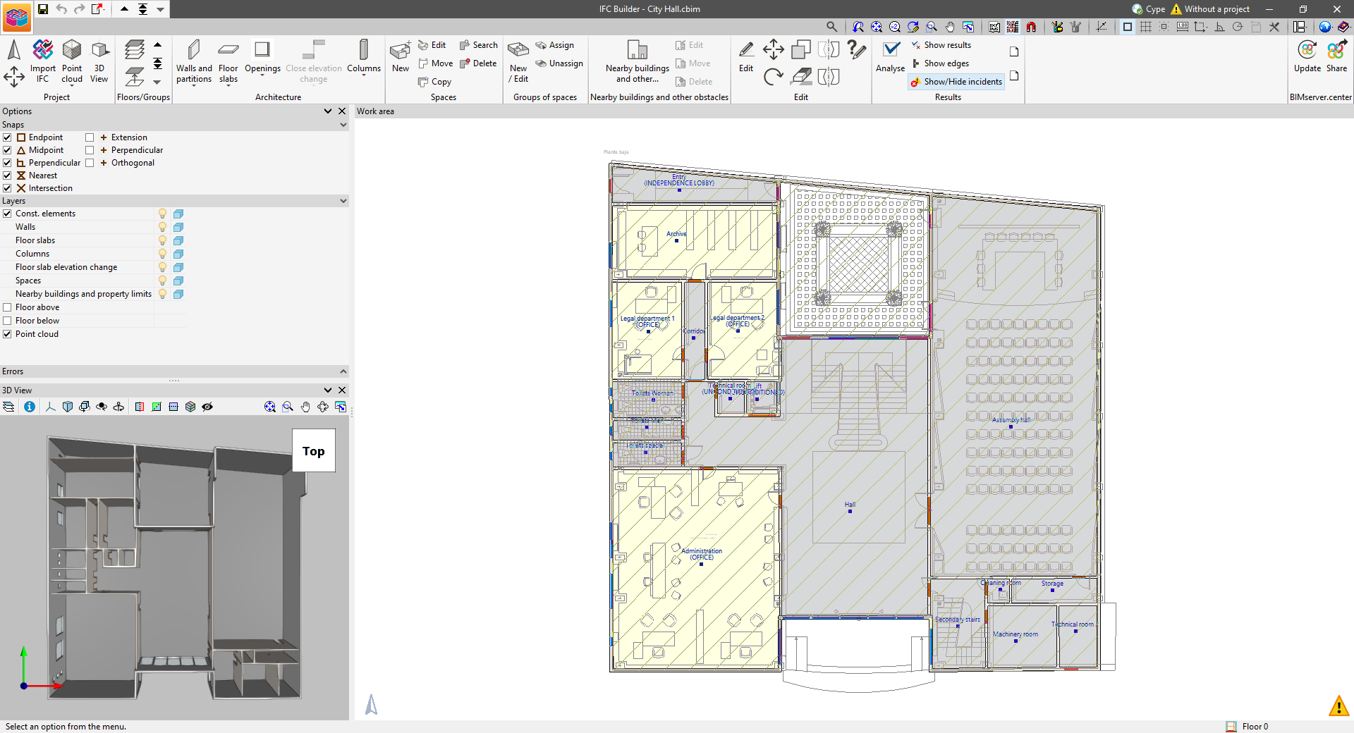
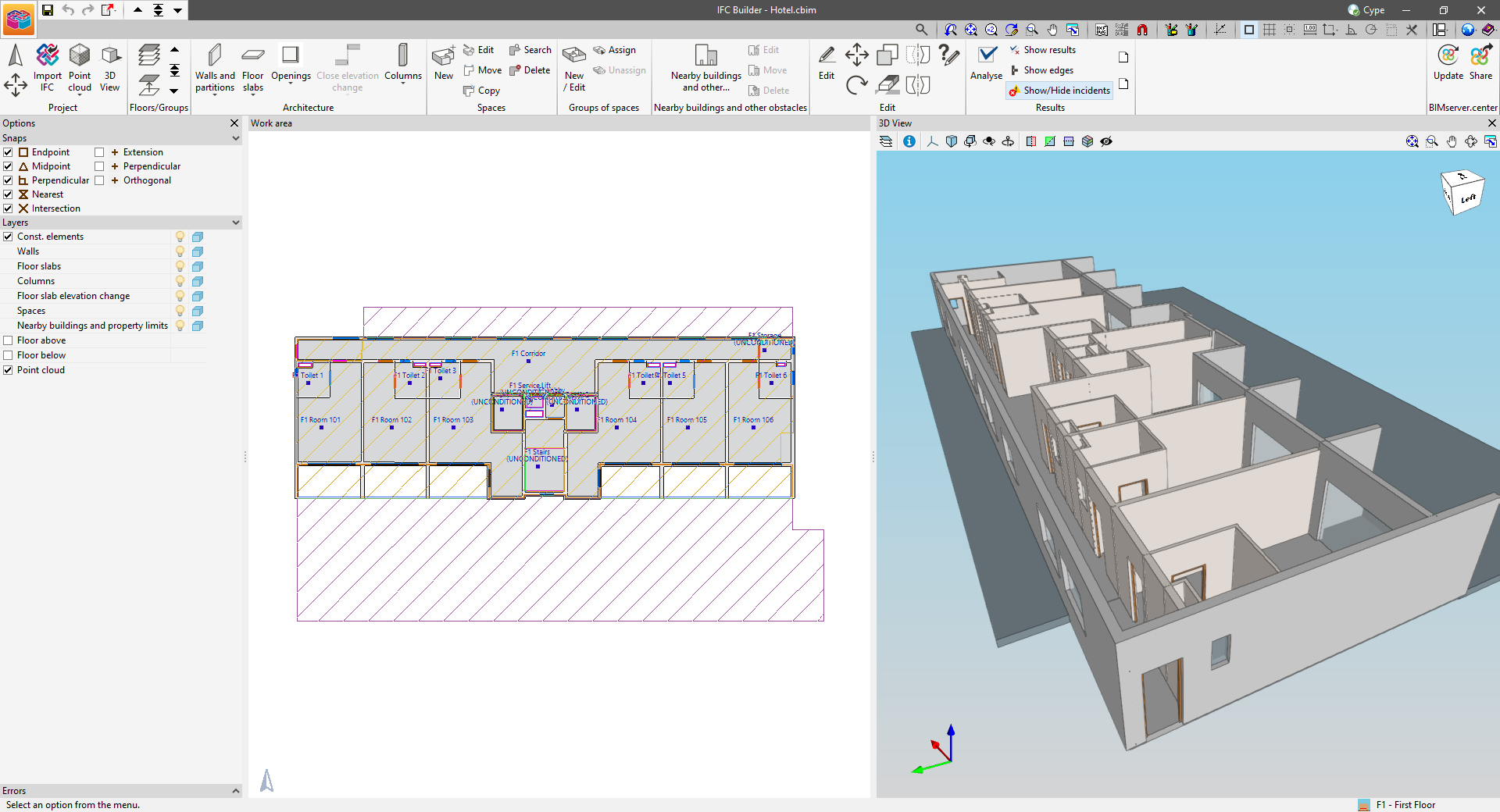
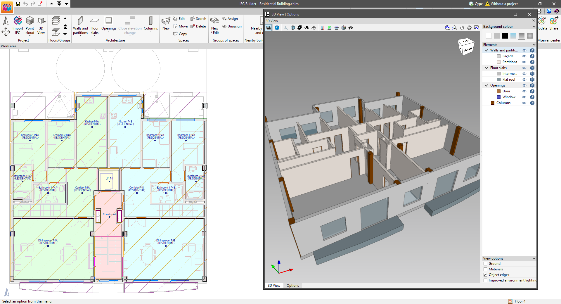
As of version 2024.c, IFC Builder includes the new dockable window system (implemented in other programs in version 2023.e) which replaces the main screen user interface. The interface is now composed of the "Work area", "Options" and "3D View" windows. These can be moved and resized. These windows can be floating windows, pinned to a location within the main application dialogue box, dragged out of the main application dialogue box, or even moved to another monitor.
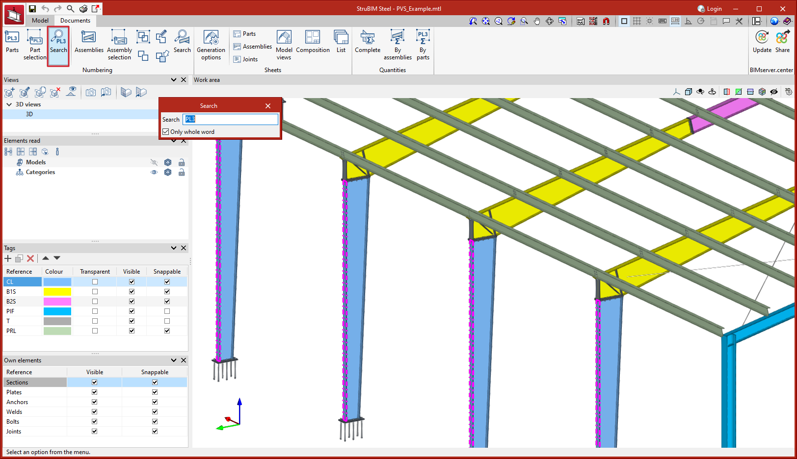
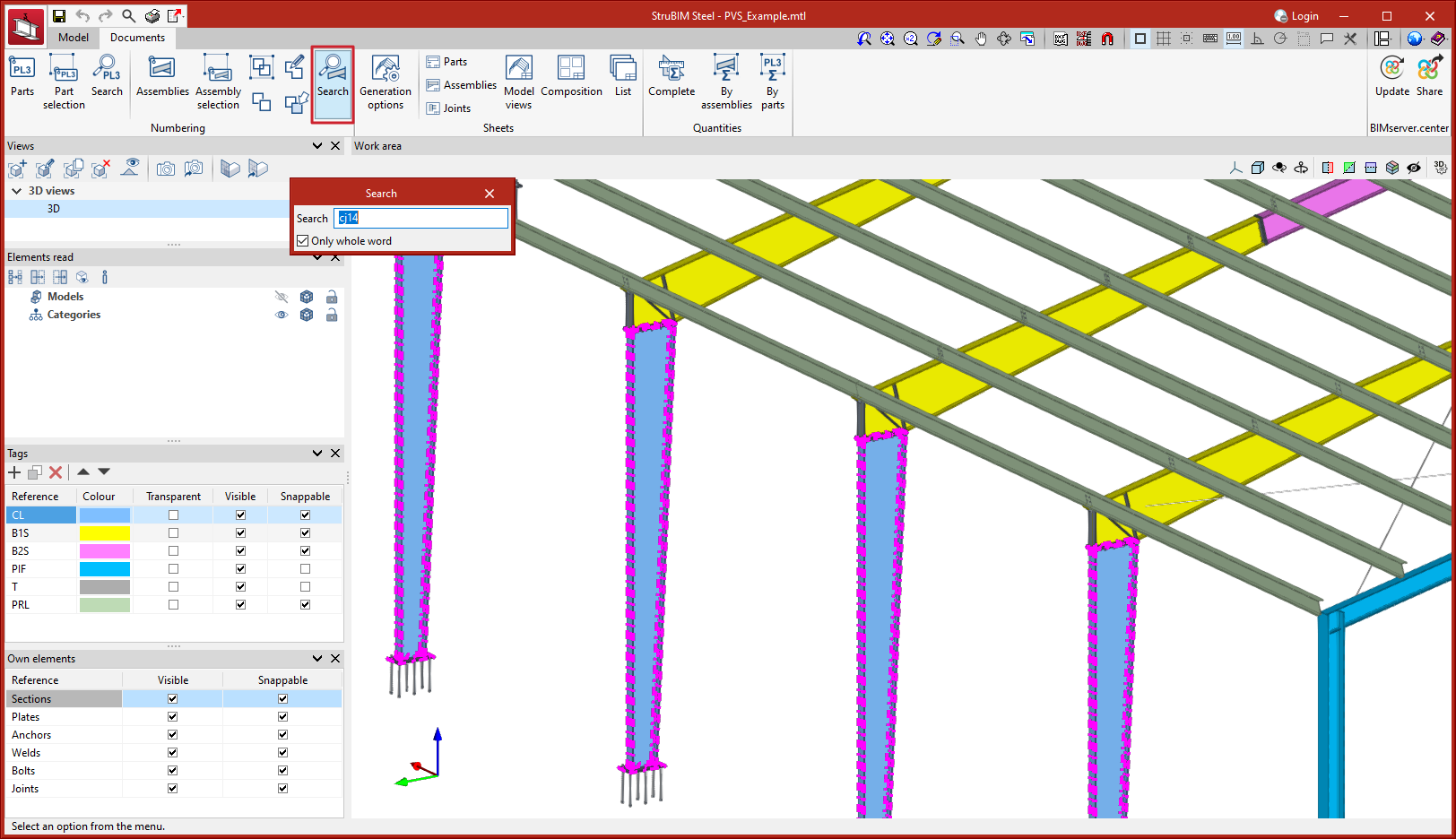
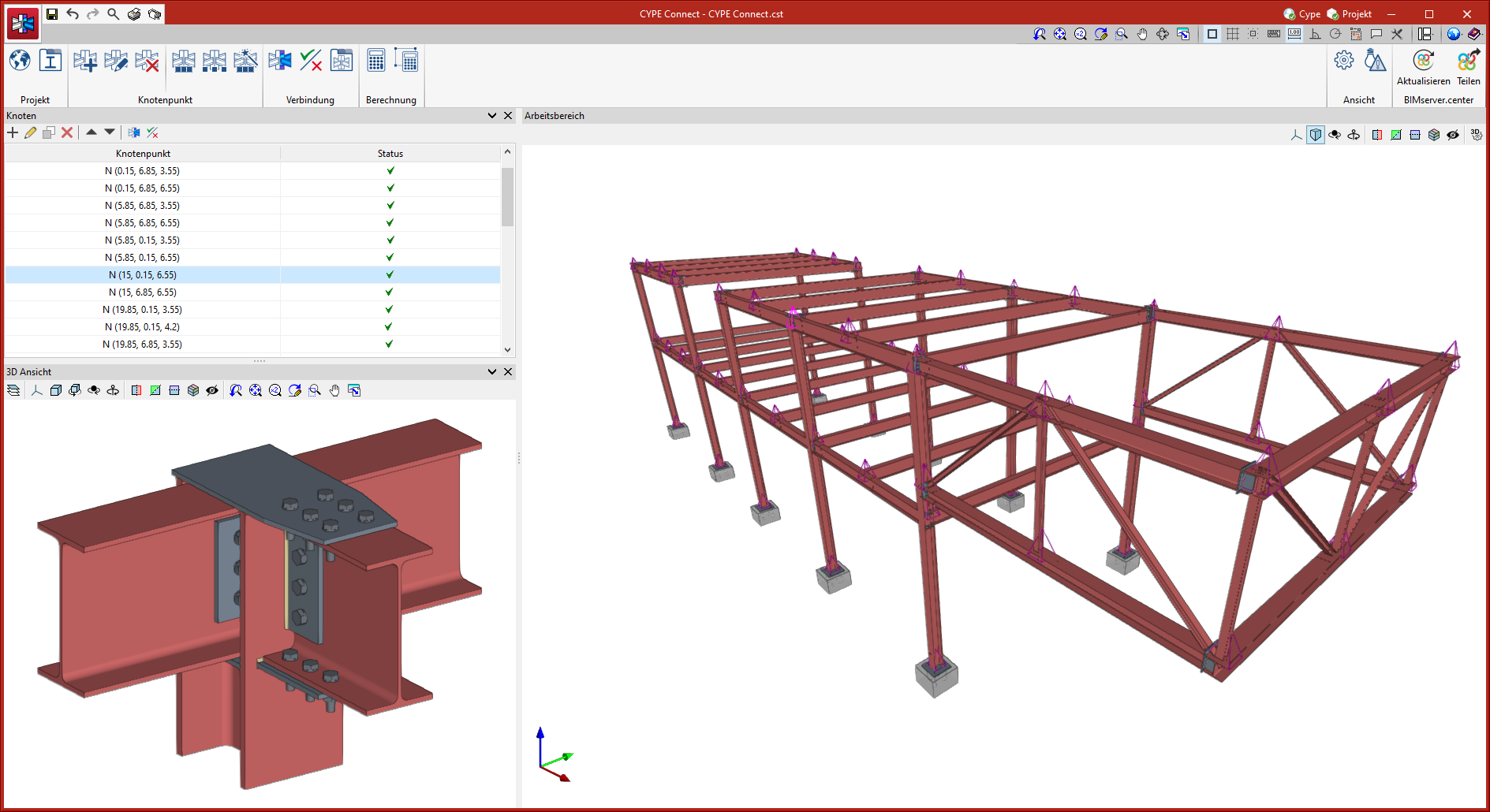
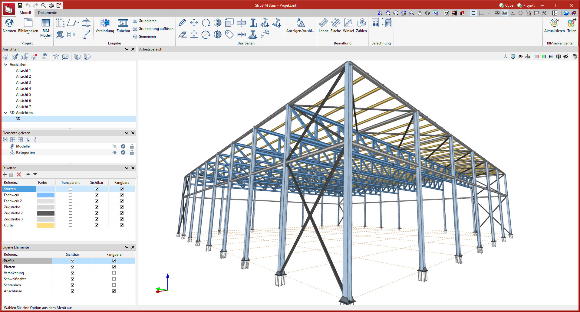
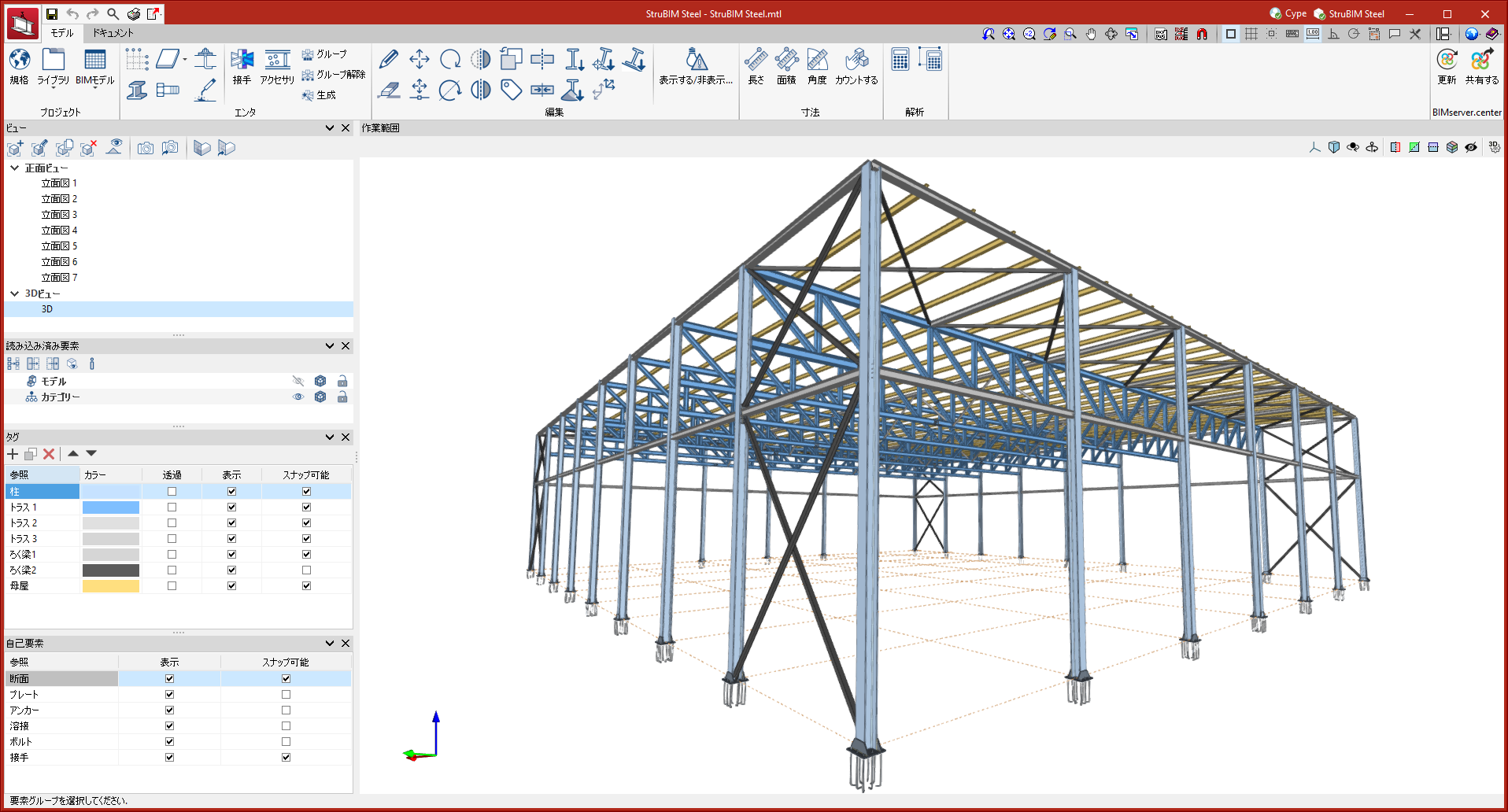
Two new search tools are implemented in StruBIM Steel version 2024.c, one to search for parts and one to search for assemblies. When selecting the tools a panel appears that allows users to enter the reference to be searched for, in the 3D view the elements corresponding to the search will be marked.
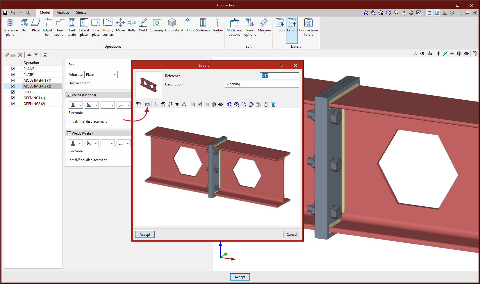
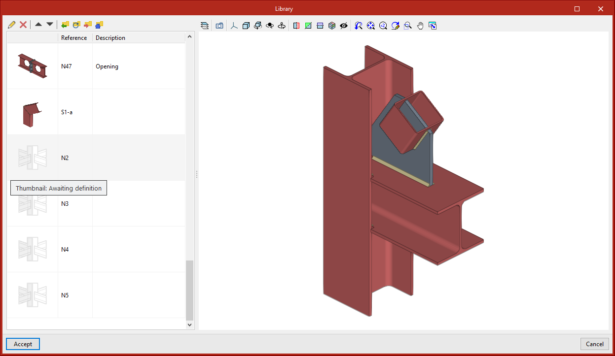
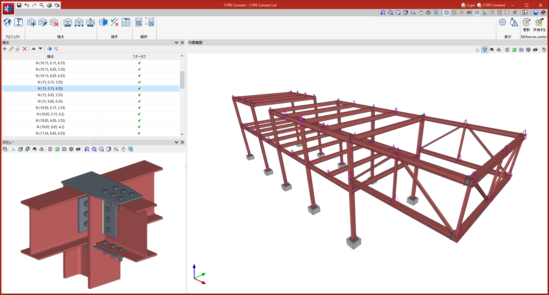
As of version 2024.c, the connection library includes a thumbnail view of the connection. This view helps users to locate connections. The export panel shows a thumbnail view by default. Clicking on "Capture the current view" will update the thumbnail by capturing an image of the 3D view.
The connections saved in the library prior to version 2024.c will appear with the thumbnail yet to be defined. To capture the thumbnail, simply click on "Capture the current view (Thumbnail)".
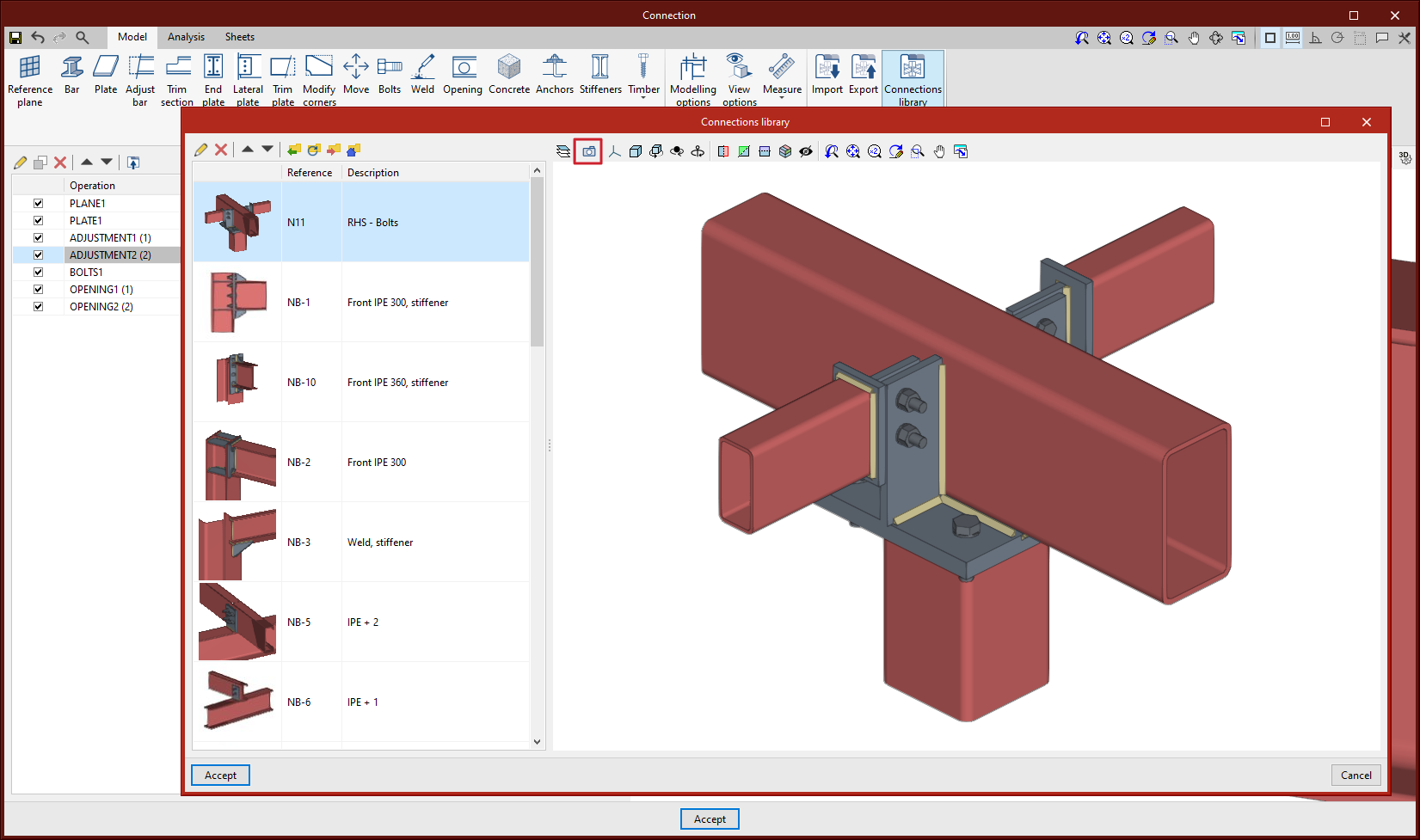
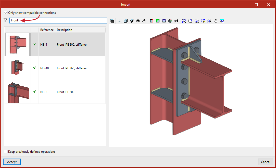
As of version 2024.c, the panel for importing library connections includes the option to filter by text. When entering text over the filter field, the list of connections will show the ones that include that text in the reference or description.
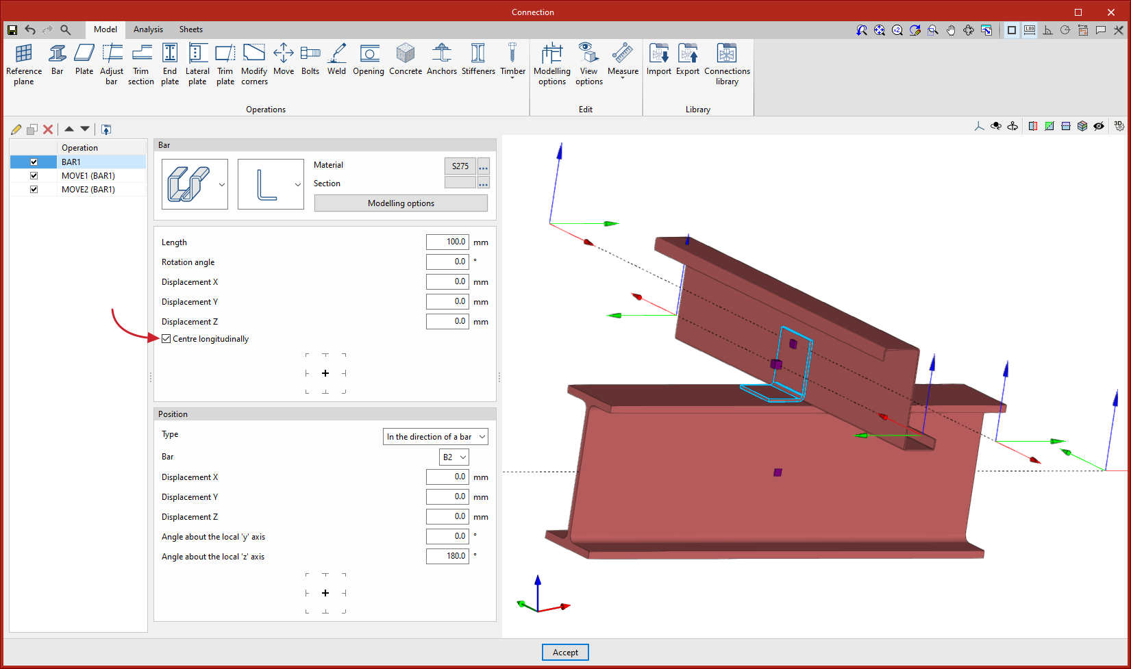
Up until version 2024.c, bars entered with the "Bar" operation always had their origin located at the start of the bar. As of version 2024.c, if the "Centre longitudinally" option is activated, the origin will be at the centre of the bar.
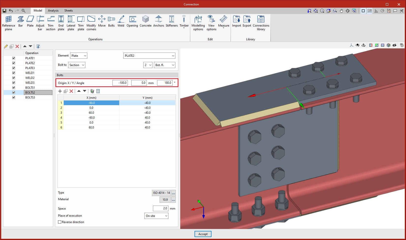
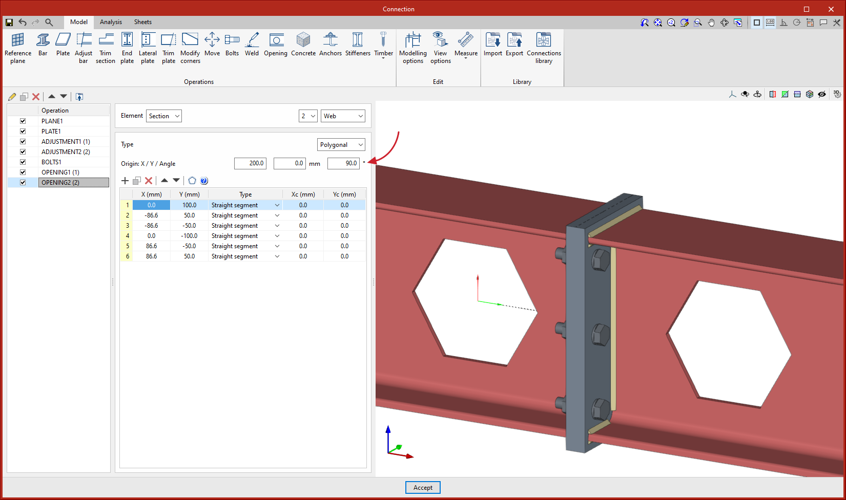
The editing of the origin of the local reference system of openings, bolts and anchors has been implemented. Above the coordinate editing table, the "Origin" section appears with the editing of the "X" and "Y" displacements and the rotation angle. These displacements are applied to the group of elements contained in the table. For bolts, the original reference system corresponds to that of the first plate, for anchors and openings it corresponds to that of the selected plate.
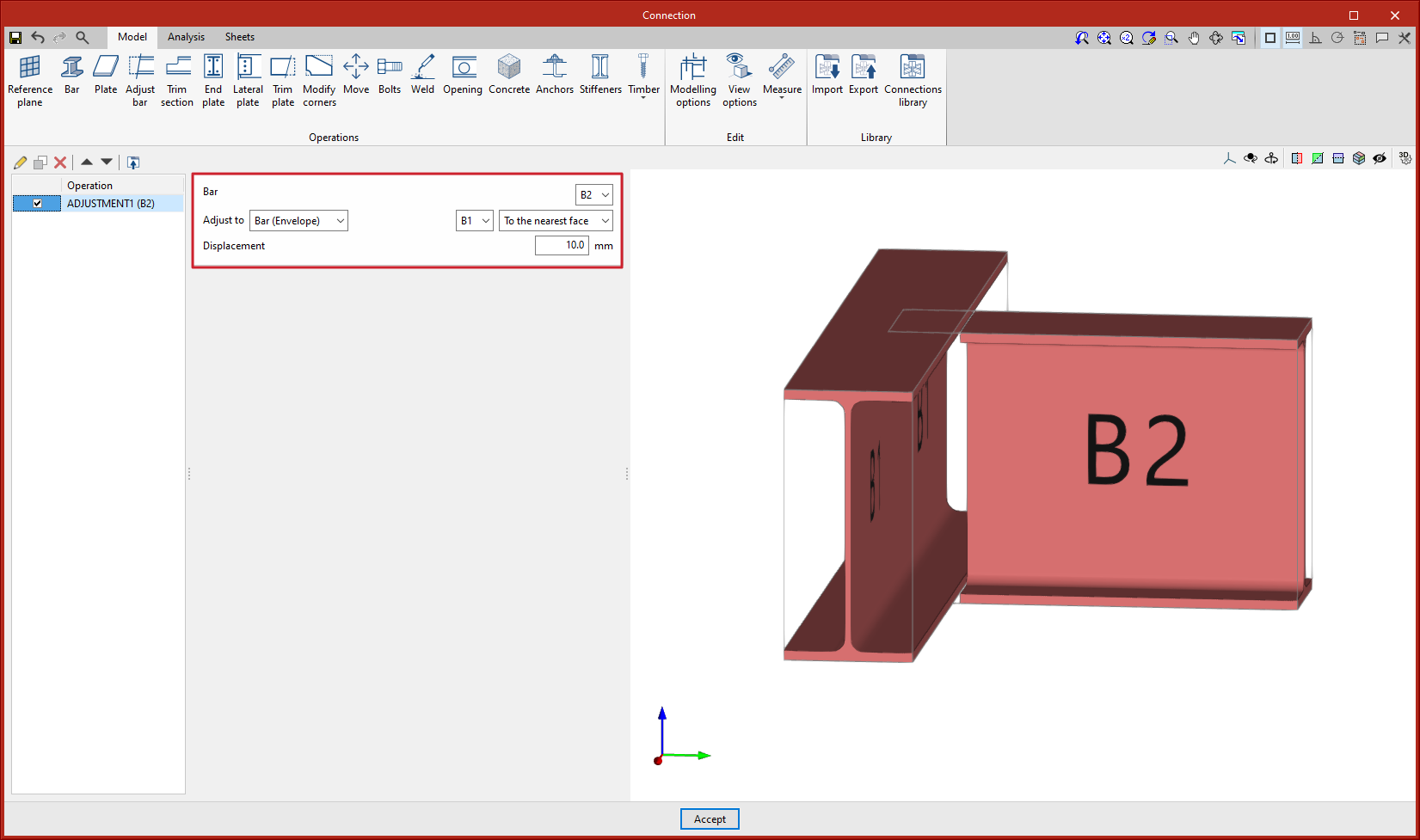
As of version 2024.c, the "Adjust bar" operation includes the option for adjusting bars to the envelope of other bars. Up until version 2024.c, to make a similar adjustment in the case of the web of an open section, users had to adjust and apply a displacement, which varies according to the width of the bar.
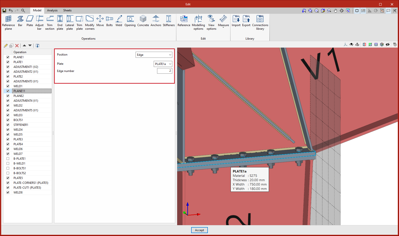
As of version 2024.c, the "Reference plane" operation includes the "Edge" option to define reference planes on the edge of a plate.
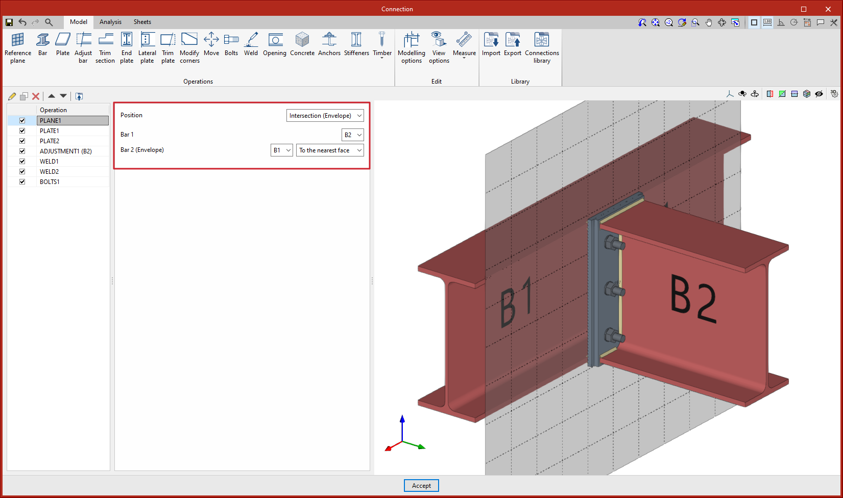
As of version 2024.c, the "Reference plane" operation includes the "Intersection (Envelope)" option to define reference planes at the intersection between a bar and the envelope of another bar. This plane can be used as a reference for attaching plates, adjusting bars, etc.
Options existing up to 2024.c allow planes to be defined in any position, the advantage of using these new options is that the position of the plane is referenced to other elements so that if the dimensions or the position of the bars change, the position of the plane will also change. This is particularly useful when combined with the use of the connection library.
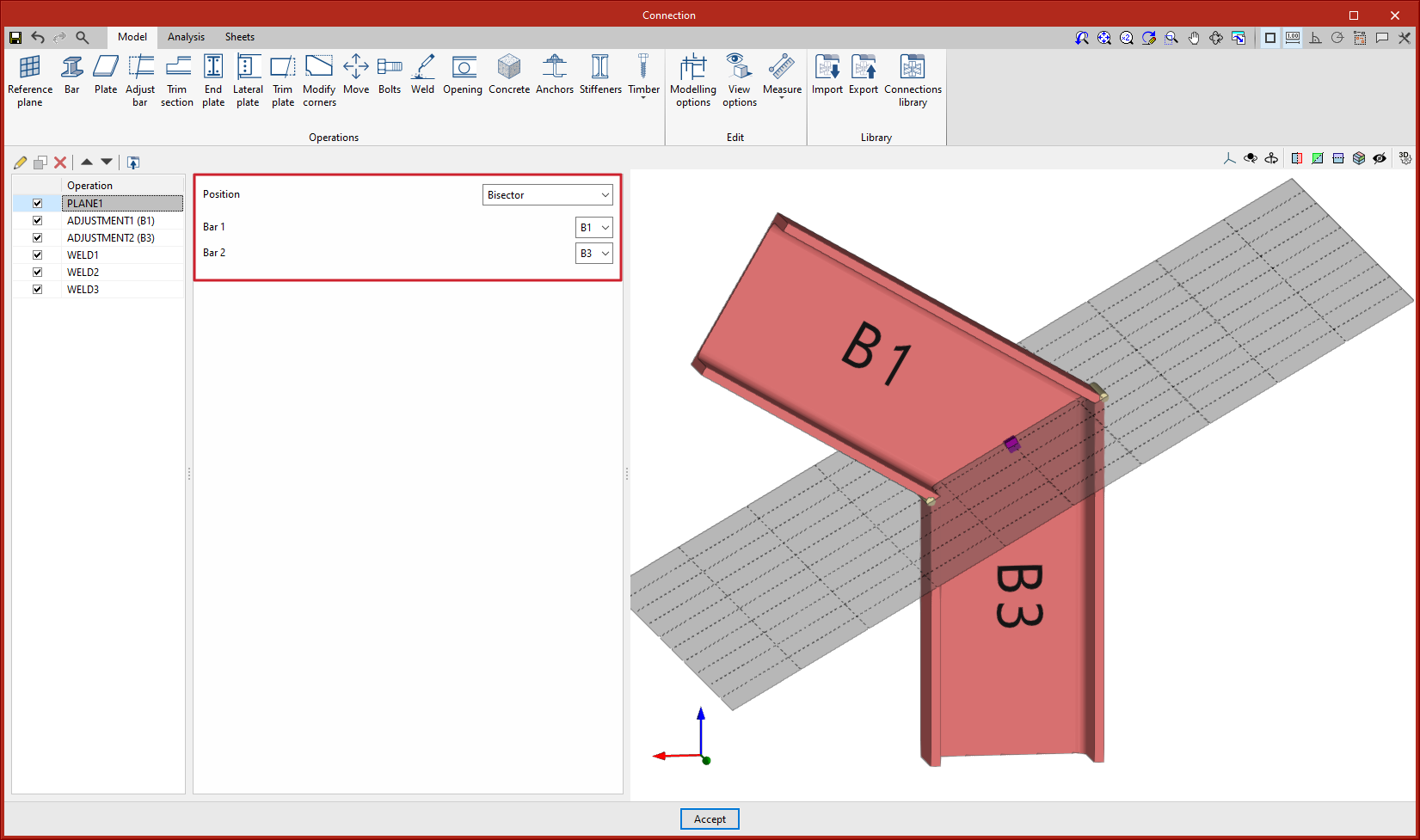
As of version 2024.c, the "Reference plane" operation includes the "Bisector" option to define reference planes on the bisector of the two bars defined by the user. This plane can be used as a reference for attaching plates, adjusting bars for splices, etc.
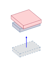
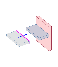
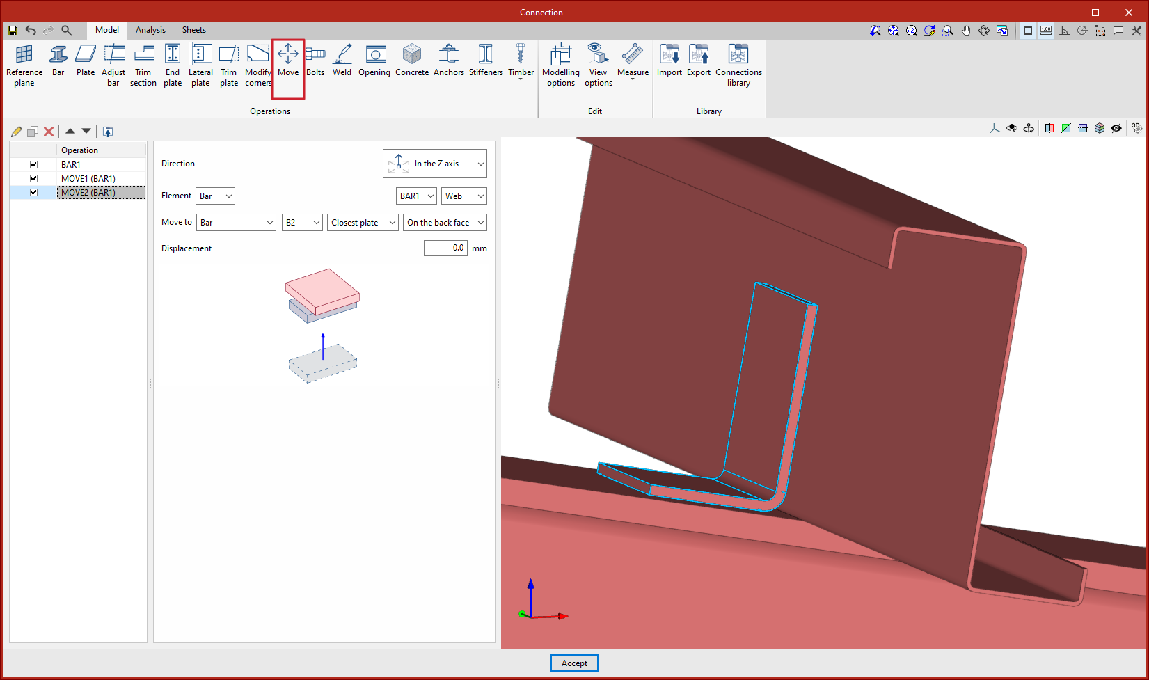
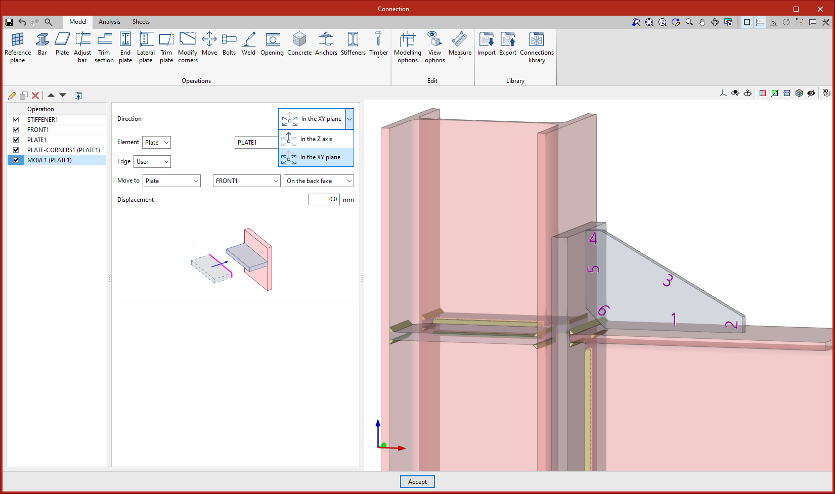
A new operation has been implemented to move bars or plates taking another element as a reference. This operation has two options, to move in the direction of the "z" axis or to move in the "xy" plane of the selected element. By means of these movements, the position of one element is linked to another. Should the reference element change its dimensions or position, the selected element will automatically move with it.
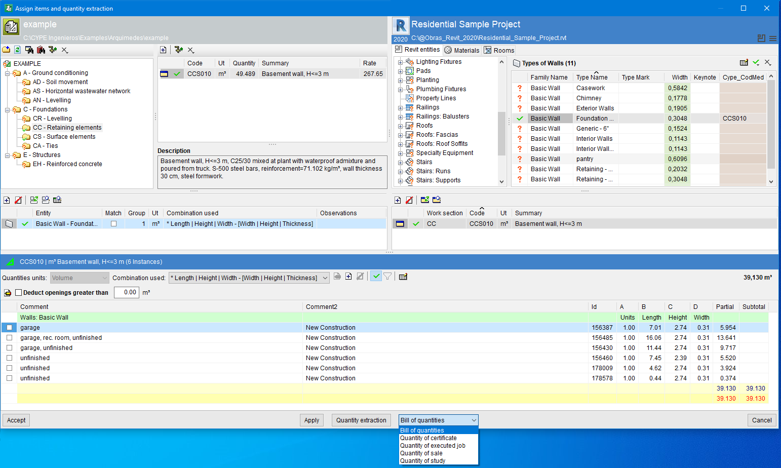
Next to the "Quantity extraction" option, a drop-down menu has been implemented in Arquimedes version 2024.c that allows users to select the type of quantities table to be used for extracting quantities.
If the quantities are to be extracted for a certificate table, it should be noted that quantity extractions are not cumulative, but partial (the contents of the quantities in the "Assign items and quantity extraction" window are always transferred to the quantity tables). Therefore, this table provides a partial quantity in progress and not at source. This means that the certificate has not been closed. The same applies if the quantity is extracted for the completed job table.
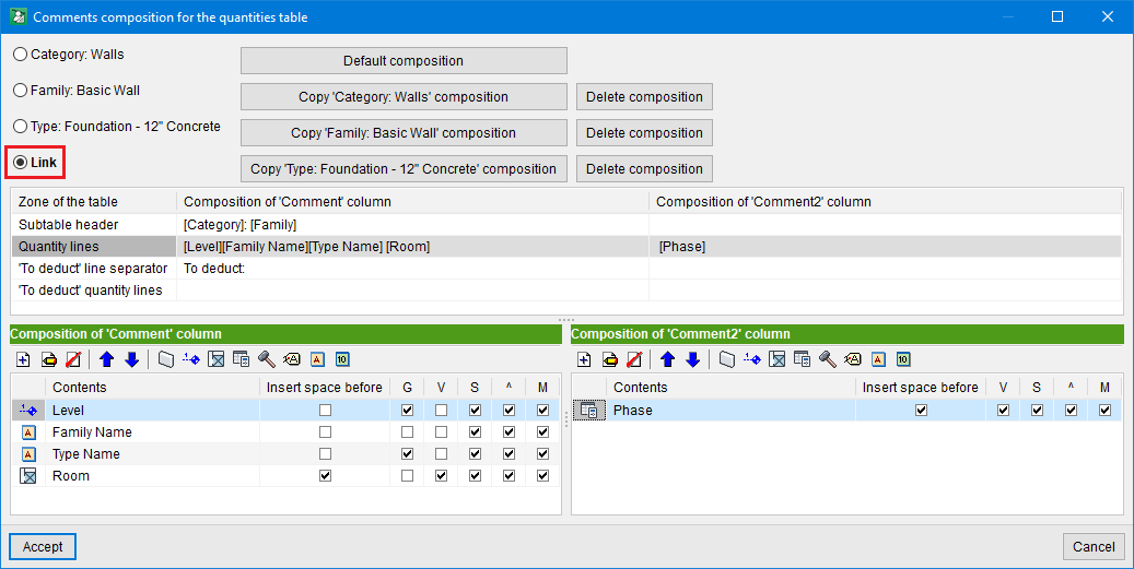
In Arquimedes version 2024.c, the "Link" option has been added to the "Comments composition for the quantities table" dialogue box. This dialogue box is opened by clicking on the edit button with the same name: "Comments composition for the quantities table", which is located next to the combination used for the extracted quantities.
The "Link" option refers to the Entity-Item linkage (assignment between the Revit entity and the Arquimedes item). This linkage has a combination for extracting quantity lines and, among other things, two comment compositions (one for each comment column, "Comment" and "Comment2"). Using the "Link" option, each of these comment compositions can now be customised for the link so that it does not affect any other links.
Entity-Item links are unique. Therefore, if the comments for the link are customised and the "Link" option is activated, this change only affects that link or Entity-Item assignment.
As of 21 September 2023, all downloads of the CYPE Connect and StruBIM Steel applications (versions 2024.b and later) from the the BIMserver.center platform will be available for installation in German and Japanese.
These applications can now be installed in the following languages:
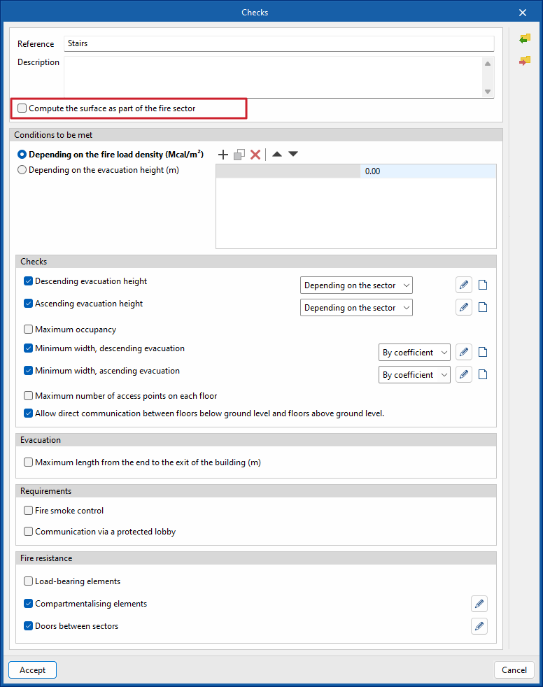
As of version 2024.c, users will be able to manually define whether they want to exclude the surface area of the different spaces from the fire compartment to which they are assigned.
The different zones that include this possibility are:
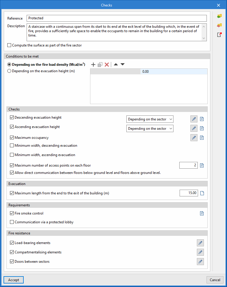
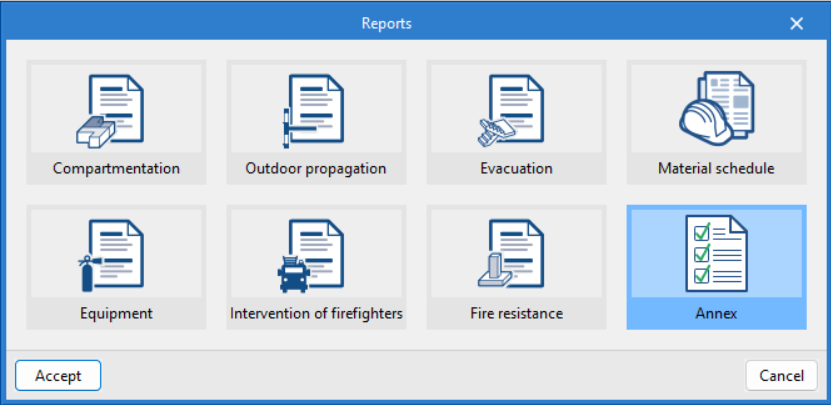
In the management of the reports, a new type of report, the Annex, has been included. In this report, users can find additional information on the fire sectors included in the project.
This information can be checked, modified and created from the checks applicable to each of the fire sectors in the standard.
As of version 2024.c of CYPEFIRE, users can manage the maximum distance travelled from the end of the staircase in the check panel ("Evacuation" section, "Maximum length from the end to the exit of the building" option).
To do this, simply activate the check on the panel and specify the maximum permissible distance.