As of version 2024.c, CYPECAD now allows users to include electrowelded mesh for use in the analysis of flat slabs in a similar way to the use of the base reinforcement. As well as designing the reinforcement taking into account the electrowelded mesh, the program also allows users to detail the reinforcement, obtain reports and drawings as well as detailed measurements of the reinforcement.
Electrowelded meshes are part of a new CYPECAD module, so in order to use them, users must have the corresponding permission in their user license.
Electrowelded mesh and base reinforcement
For analysis purposes, the electrowelded mesh and the base reinforcement are treated in the same way, bearing in mind that, when designing the slab reinforcement, both elements provide a uniform mechanical ratio throughout the slab.
For flat slabs, the program now allows users to choose between assigning base reinforcement or electrowelded mesh.
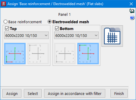
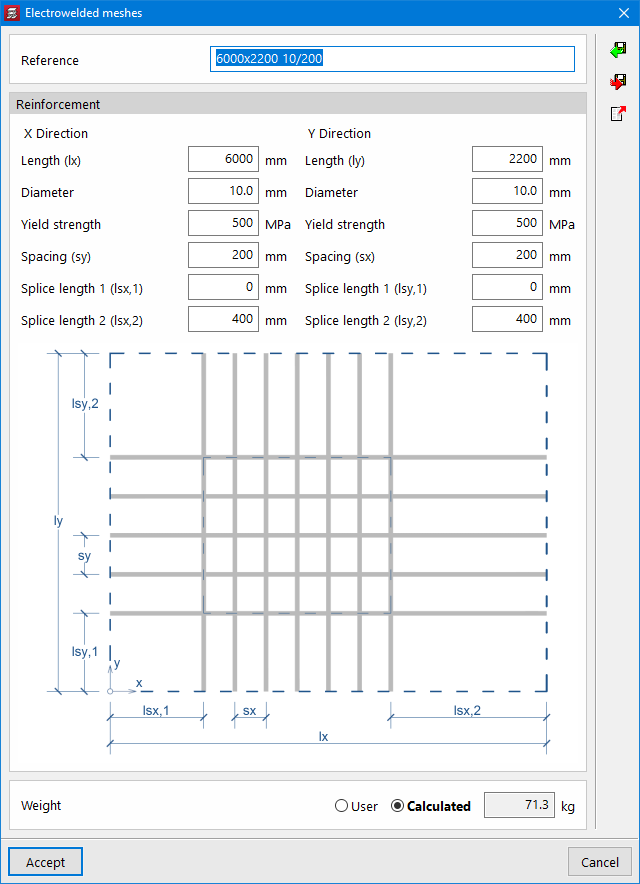
When selecting the "Electrowelded meshes" option, the program allows users to choose from all the references defined in the library. New meshes can be added to the library by defining their reference and characteristics.
The X and Y axes of the mesh can be made to coincide with the reinforcement axes of the slab, or they can be rotated by 90°.
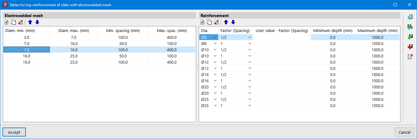
The program designs the necessary reinforcement bars in addition to the mesh, using the reinforcement tables for slabs with electrowelded mesh.
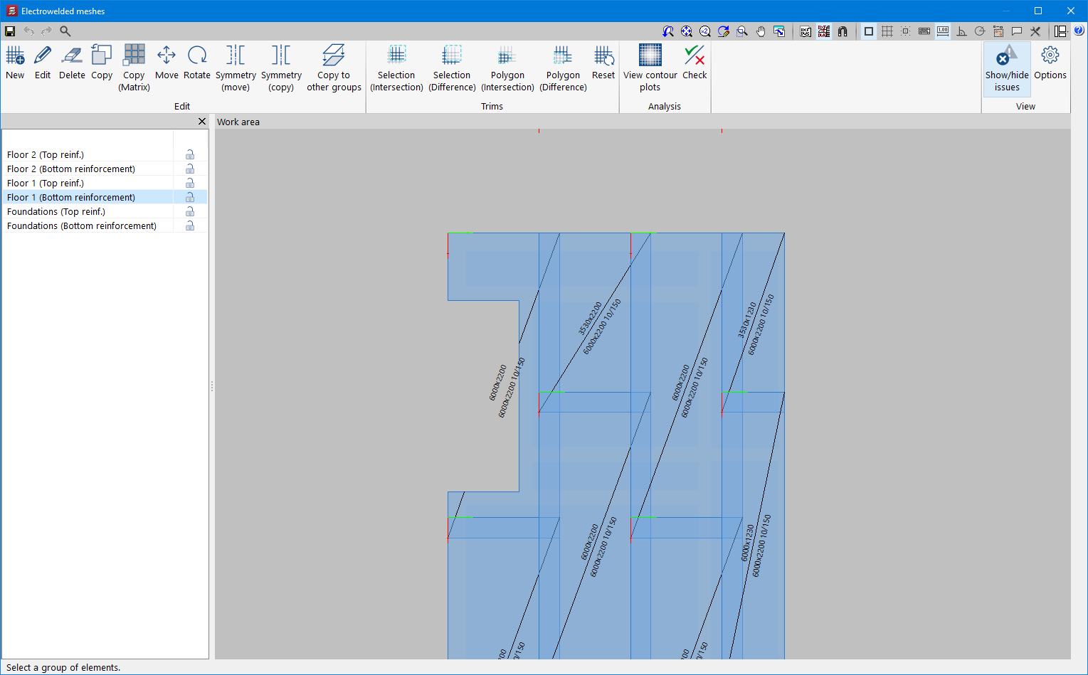
Editing electrowelded meshes
If meshes have been assigned to any of the panels, the "Electrowelded meshes" option will be activated in the "Flat/Waffle slabs" menu in the "Results" tab. After analysing the job, the program will automatically generate a mesh distribution proposal for the top and bottom reinforcement of the flat slab sections, which can be checked and modified using this option (Electrowelded meshes). The editor allows users to delete, move and trim the existing meshes. It also includes different features to make it easier to enter new mesh in the desired areas.
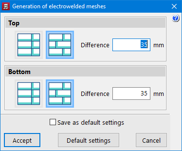
The criteria for automatically generating the mesh distribution can be configured in the menu "Job" > "Floor slab options" > "Generation of electrowelded meshes".
The layout of the electrowelded meshes should ensure that the floor slab panel is completely covered by the mesh panels, taking into account that each panel should overlap with the next one in the overlapping area.
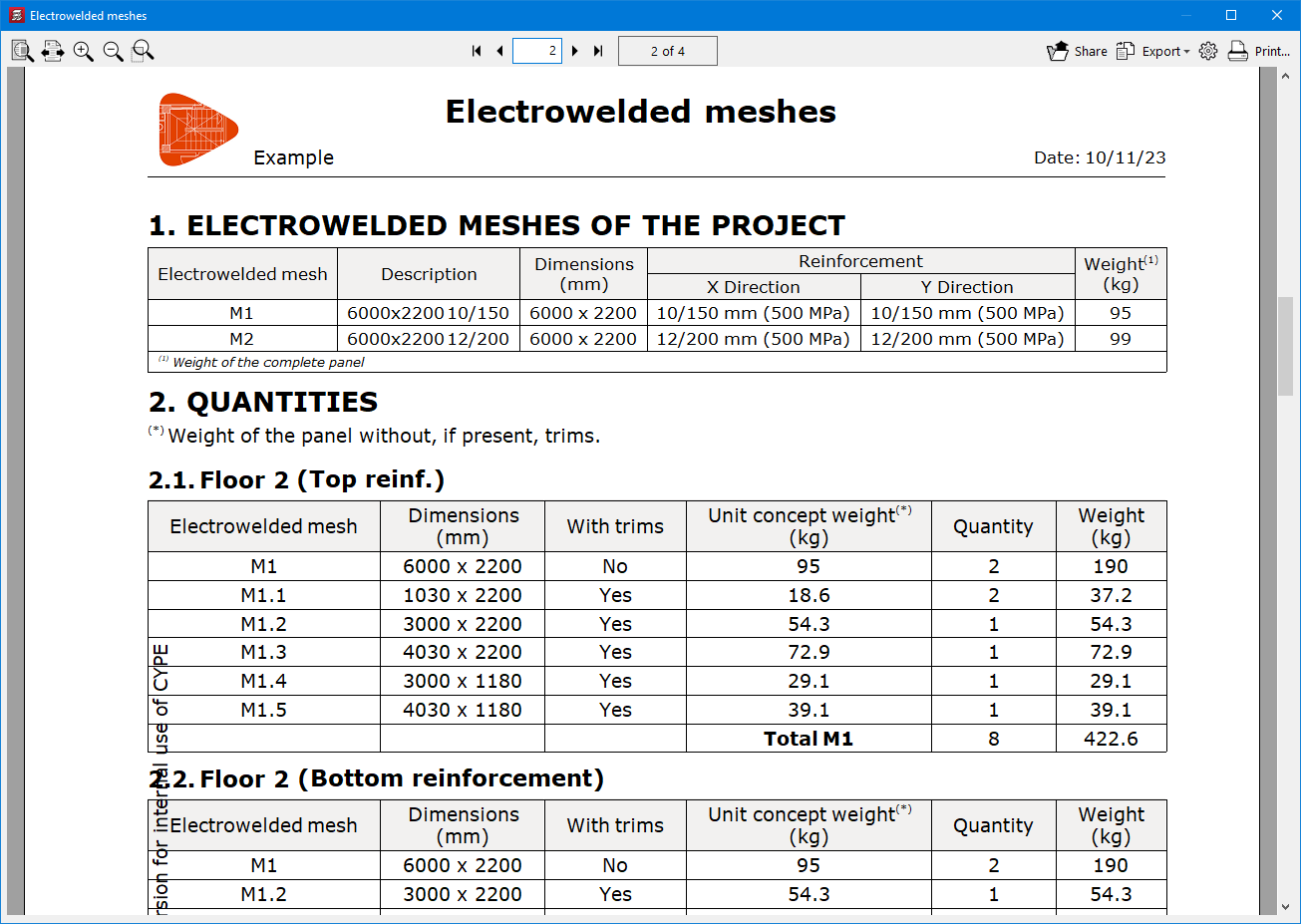
Electrowelded meshes report
The "Reports" menu of the program includes the new "Electrowelded meshes" report, which contains information on the types of mesh used in the job as well as their characteristics and the quantity of panels per floor, taking into account, where appropriate, the necessary trimming to adapt them to the geometry of the floor slab.
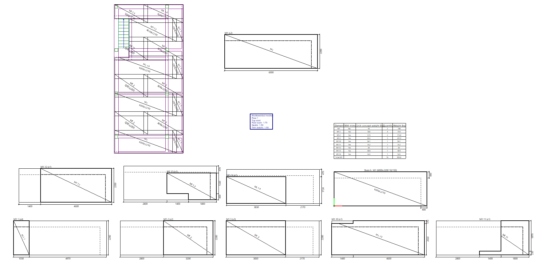
Electrowelded meshes drawing
The "Drawings" menu of the program includes the new "Electrowelded mesh" type of drawing. As with other CYPECAD floor plans, the elements to be shown can be configured in this drawing by means of a series of options.
The drawing shows a floor with the layout of the electrowelded meshes, a detailed model of the different meshes used in the job, and details of each of the trimmed panels. A summary table with the quantities and weights of each of the elements in the drawing is also included.