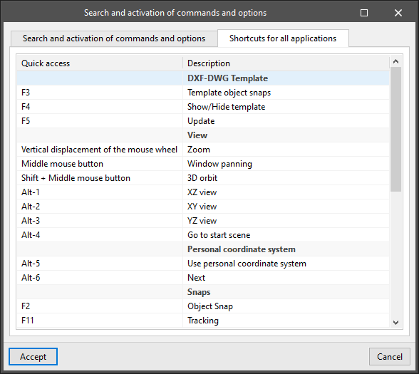
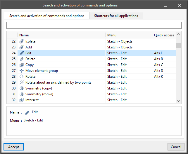
CYPE apps have keyboard shortcuts common to all programs. In versions before 2024.e, each program displayed the keyboard shortcuts for each app via the "Search and activation of commands and options" in the top left-hand corner of the programs.
As of version 2024.e, the "Shortcuts for all applications" tab has been implemented in the dialogue box displayed when selecting this option and it shows all the keyboard shortcuts common to CYPE apps.
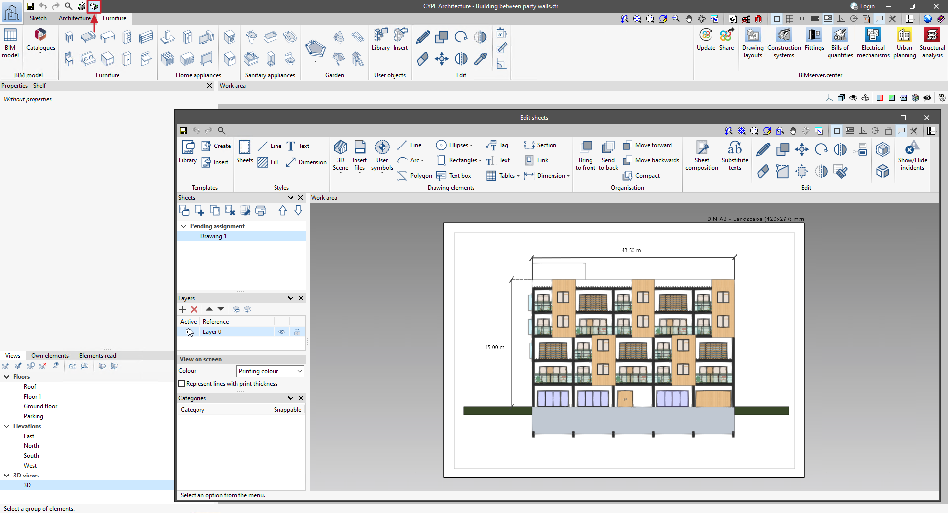
In version 2024.e, all the features from the Open BIM Layout program have been integrated into CYPE Architecture. Thanks to this, architectural drawings of the model can be generated by CYPE Architecture without having to leave the program.
To learn more about how plans can be created, see the Open BIM Layout Learning resources section.
Integrating the Open BIM Layout features in CYPE Architecture includes specific options for generating carpentry drawings (windows, doors and skylights) in an extremely quick and easy way.
The steps to be followed to generate the carpentry drawings based on the types that exist in the job are as follows:
- Access the carpentry drawings
Access the carpentry drawings for doors, windows and skylights from the "Types" button. Each type of window, door or skylight will have its own dimensioned view that can later be joined together in a single carpentry drawing. Select the type for which you want to create the carpentry drawing and the "Carpentry drawings" option, this will open the sheet editing. - Automatically generate the dimensioned view and individual description of each window
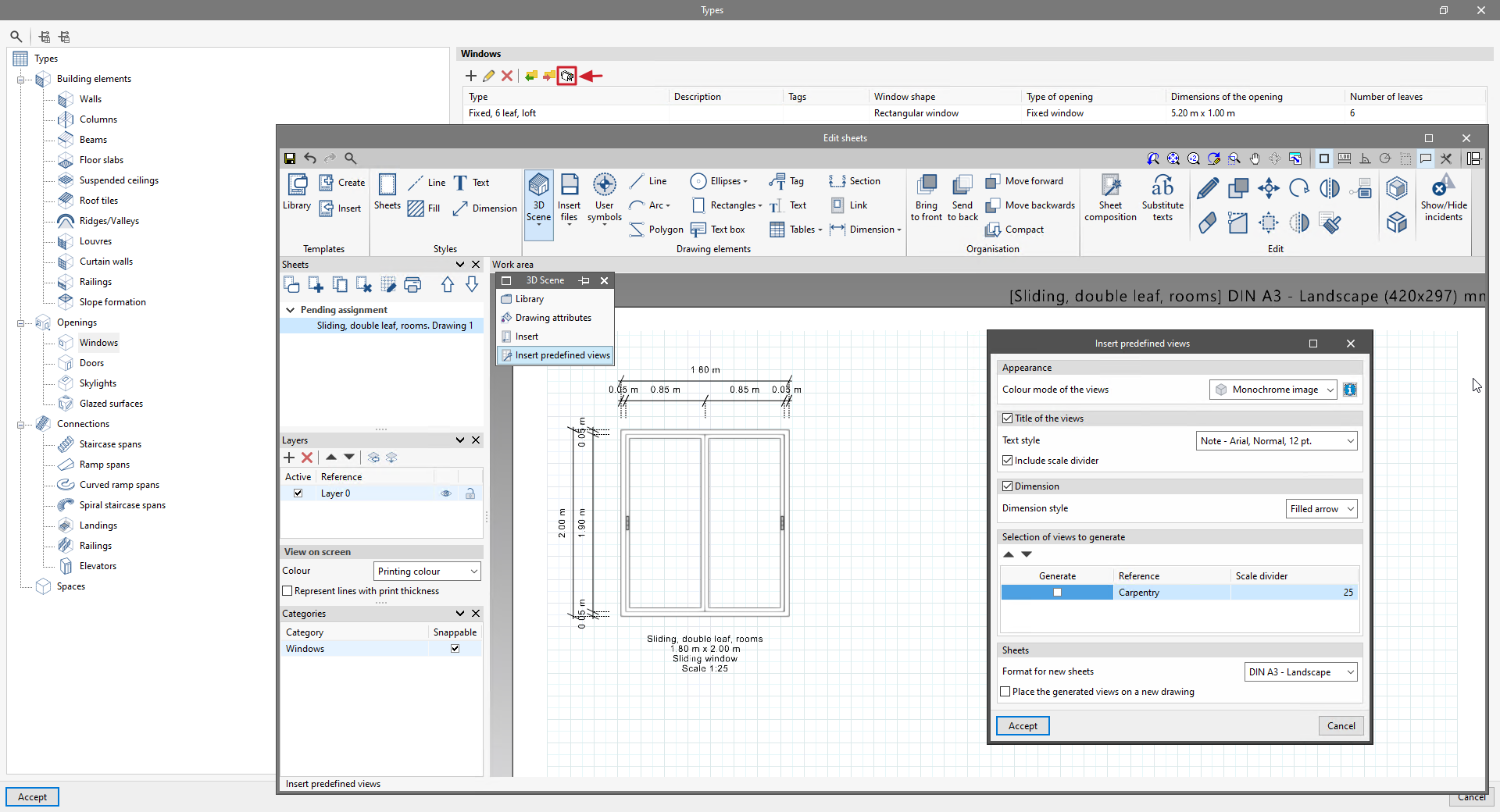
In the sheet editing select the "3D scenes" option and choose "Insert predefined views". Choose your preferences from the various options available for inserting the predefined view and accept the window. This will automatically create a dimensioned view together with the description of the window (reference, size, opening type and scale). Please note that from this sheet editing screen, any modifications can be made to the sheet. Save the sheet and repeat the same process with all the types of doors, windows and skylights to be included in the carpentry drawing.
- Assemble the carpentry drawing including all the previously generated sheets
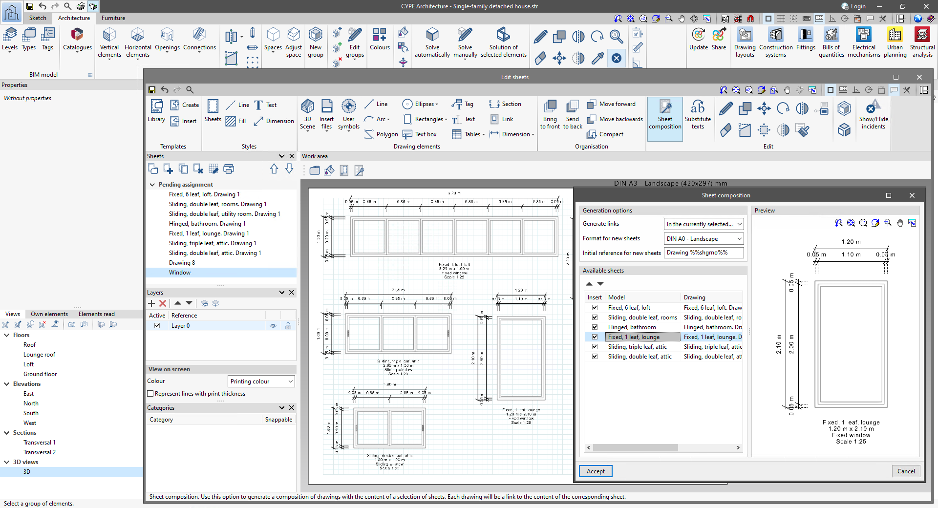
Finally, proceed to join all the individually generated sheets into a single carpentry drawing. To do this, open "Drawings" and create a new sheet. Please make sure that no model is selected when creating a new sheet. Once the sheet has been created, use the "Sheet composition" feature to add all the carpentry views you wish to insert. The program will automatically distribute the carpentry views on the sheet.
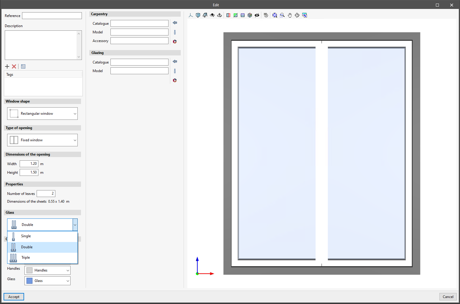
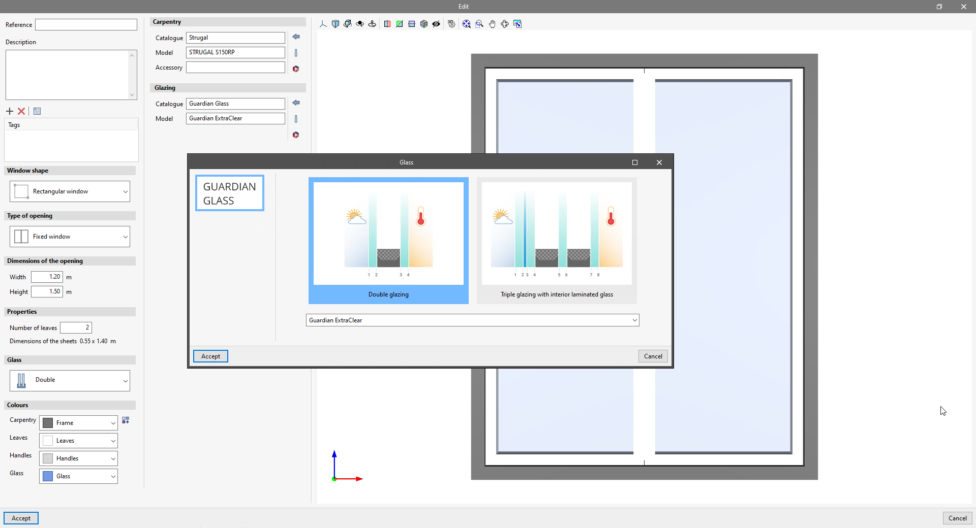
There is a new feature for windows to indicate the type of glass in the window: monolithic, double or triple glazing.
The glass type information is exported to the BIM model and can be used in other Open BIM apps.
An option has been added so that products from window manufacturers and window fittings manufacturers can be downloaded for use in the BIM model generated by the program.
In version 2024.e of CYPE Architecture, new shortcuts to its most commonly used tools have been implemented:
SKETCH TAB
| Command | Shortcut |
|---|---|
| Line | ALT + L |
| Quadrilateral | ALT + S |
| Arc | ALT + A |
| Delete | ALT + B |
| Copy | ALT + C |
| Edit | ALT + E |
| Move | ALT + D |
| Rotate | ALT + R |
| Invert | ALT + I |
| Extrude | ALT + M |
ARCHITECTURE TAB
| Command | Shortcut |
|---|---|
| Delete | CTRL + B |
| Copy | CTRL + C |
| Move | CTRL + D |
| Rotate | CTRL + R |
| Edit | CTRL + E |
| Measure | CTRL + M |
| Wall | CTRL + W |
| Floor slab | CTRL + S |
| Door | CTRL + P |
| Window | CTRL + V |
These shortcuts (together with the general shortcuts) can always be found in the "Search and activation of commands and options" option, as indicated in the new feature "Shortcuts for all applications", which is common to all CYPE programs.
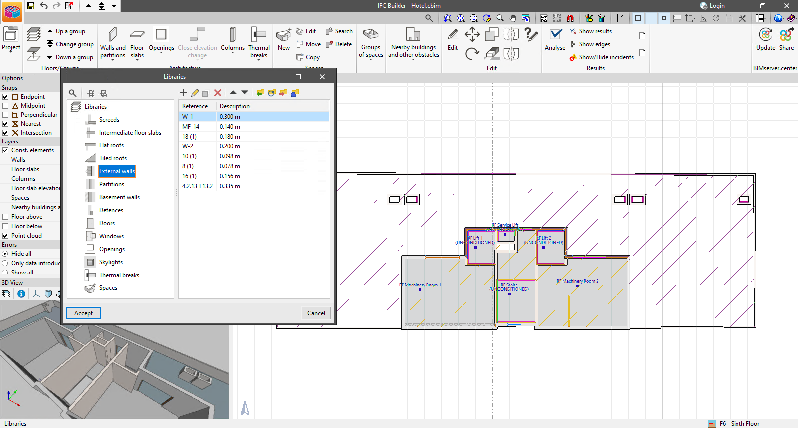
The "Libraries" option has been added to the "Project" group in the toolbar.
This button displays a window which allows users to access the types defined for the components of the IFC Builder model.
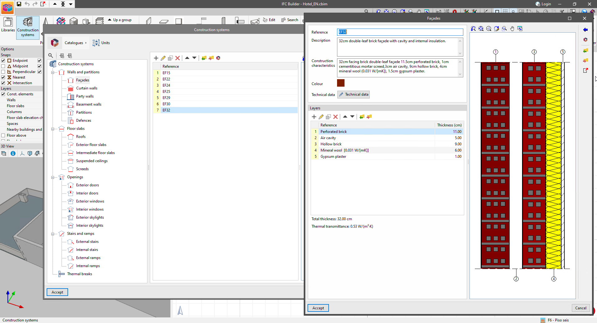
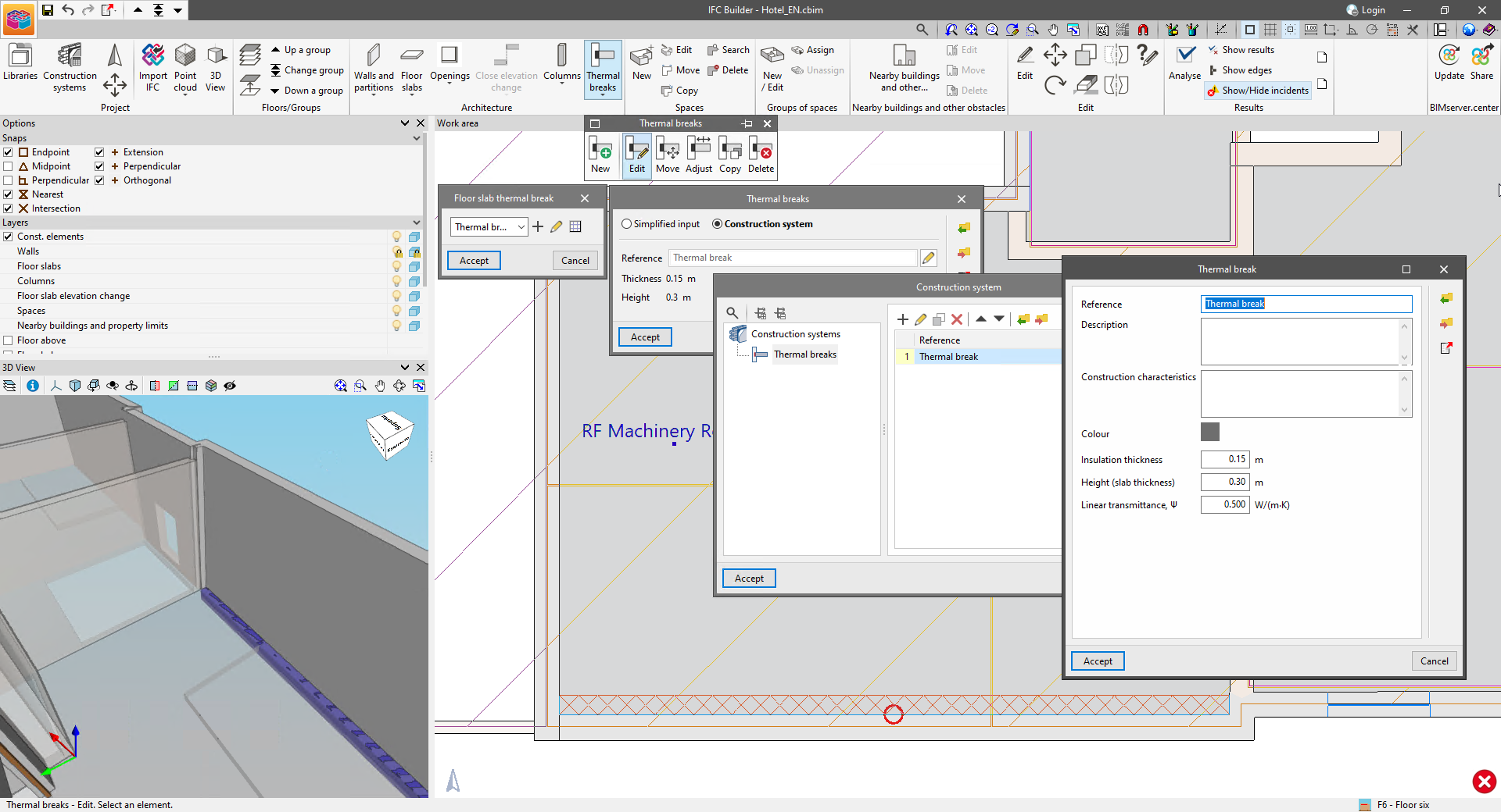
As of version 2024.e, IFC Builder includes the definition of construction systems for the components of the geometric model.
To manage the construction systems of the IFC Builder project, the "Construction systems" option has been added to the "Project" group in the program's toolbar. Construction systems can be defined the same way as in the Open BIM Construction Systems program.
Therefore, systems can be shared between the two programs via the options for "importing" and "exporting" elements on disk.
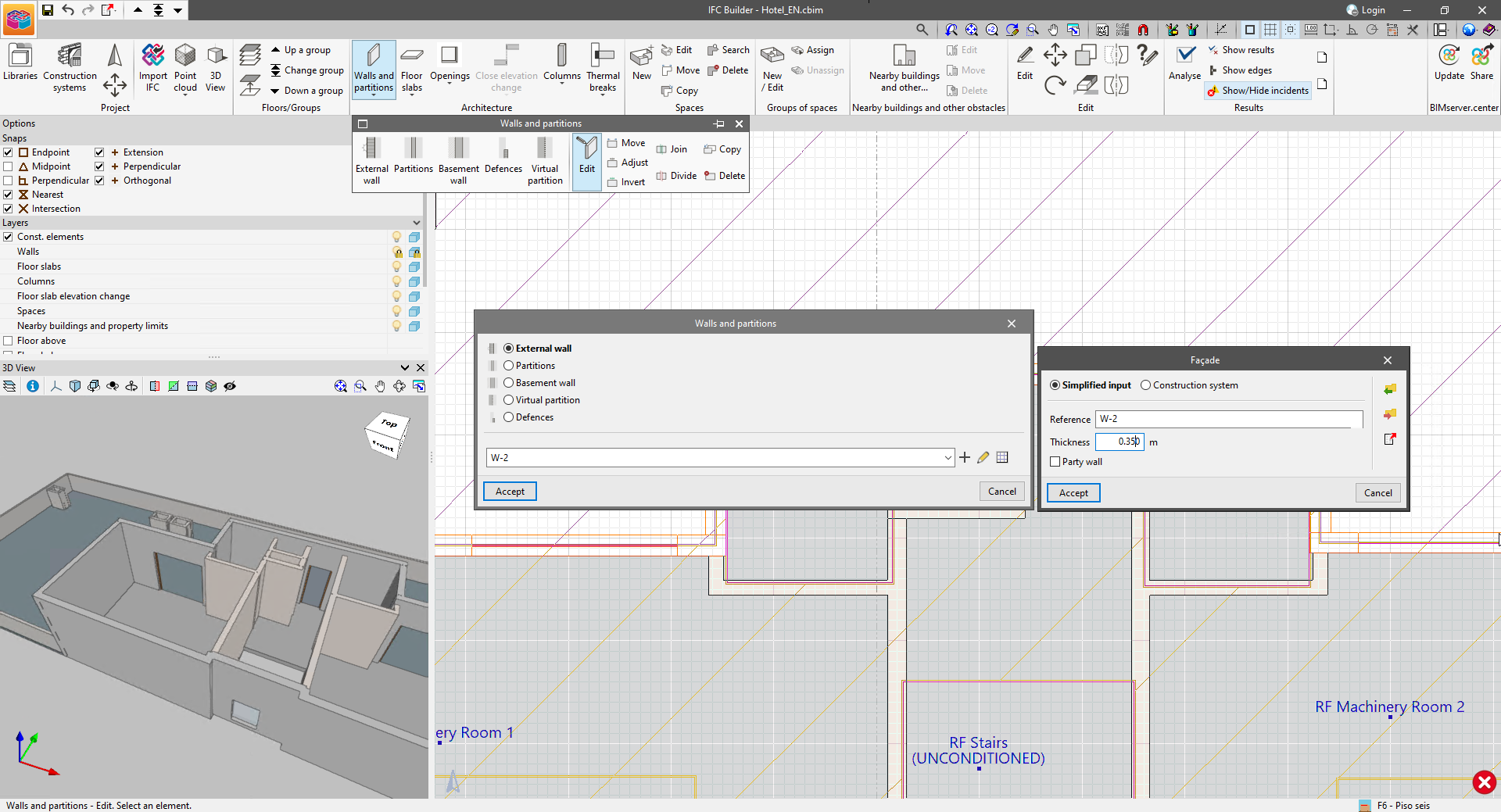
By entering a new type for the elements in the "Architecture" group in the toolbar, users can now choose between a "simplified definition" or a "construction system". This way, the dimensions of the geometrical elements will be determined from the properties of the selected system.
It is important to note that the characteristics of the construction systems and their link to the components of the model can be shared in a project on the BIMserver.center platform. Thermal and acoustic simulation tools can read it and incorporate it into their analysis models, provided that the version of these tools used is version 2024.e or later.
In IFC Builder version 2024.e, the "Thermal breaks" option has been added to the "Architecture" group in the toolbar. By clicking on it, a menu with the following buttons is displayed:
- New. Allows a new thermal break to be entered into the work area.
- Edit. Allows users to edit the properties of a thermal break.
- Move. Allows users to change the position of a thermal break. They can be moved parallel to their position or one of their ends can be moved.
- Adjust. Allows users to change the position of the thermal break with respect to the reference line.
- Copy. Allows users to copy the type and description of one thermal break to another.
- Delete. Allows users to delete thermal breaks.
The thermal breaks used in the model can be shared in a project on the BIMserver.center platform using the standard IFC file generated by IFC Builder.
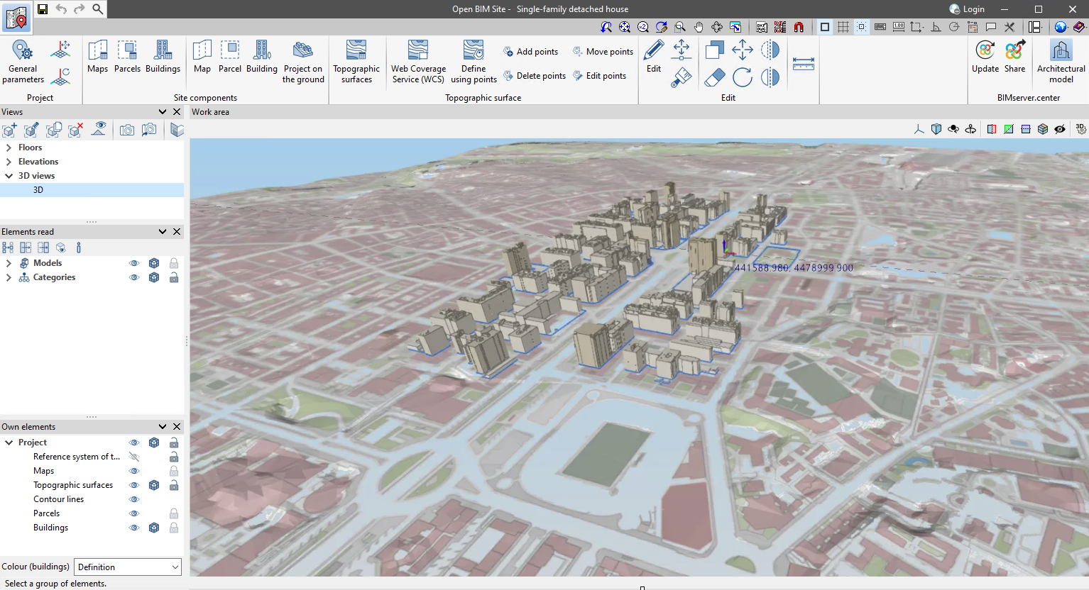
As of version 2024.e, Open BIM Site allows maps to be obtained through WMS services from the following data sources:
- Madrid (Spain)
- sigma Madrid - Cartografía actualizada. Servicio de mapas en tonos grises.
- sigma Madrid - Cartografía actualizada. Servicio de mapas en color.
- geoportal Madrid - Ortofoto 2022. Entorno de Plaza de España, Calles de Gran Vía, Mayor y Puerta de Alcalá. 1,5 cm.
- geoportal Madrid - Ortofoto 2019. Resolución 10 cm. Verdadera
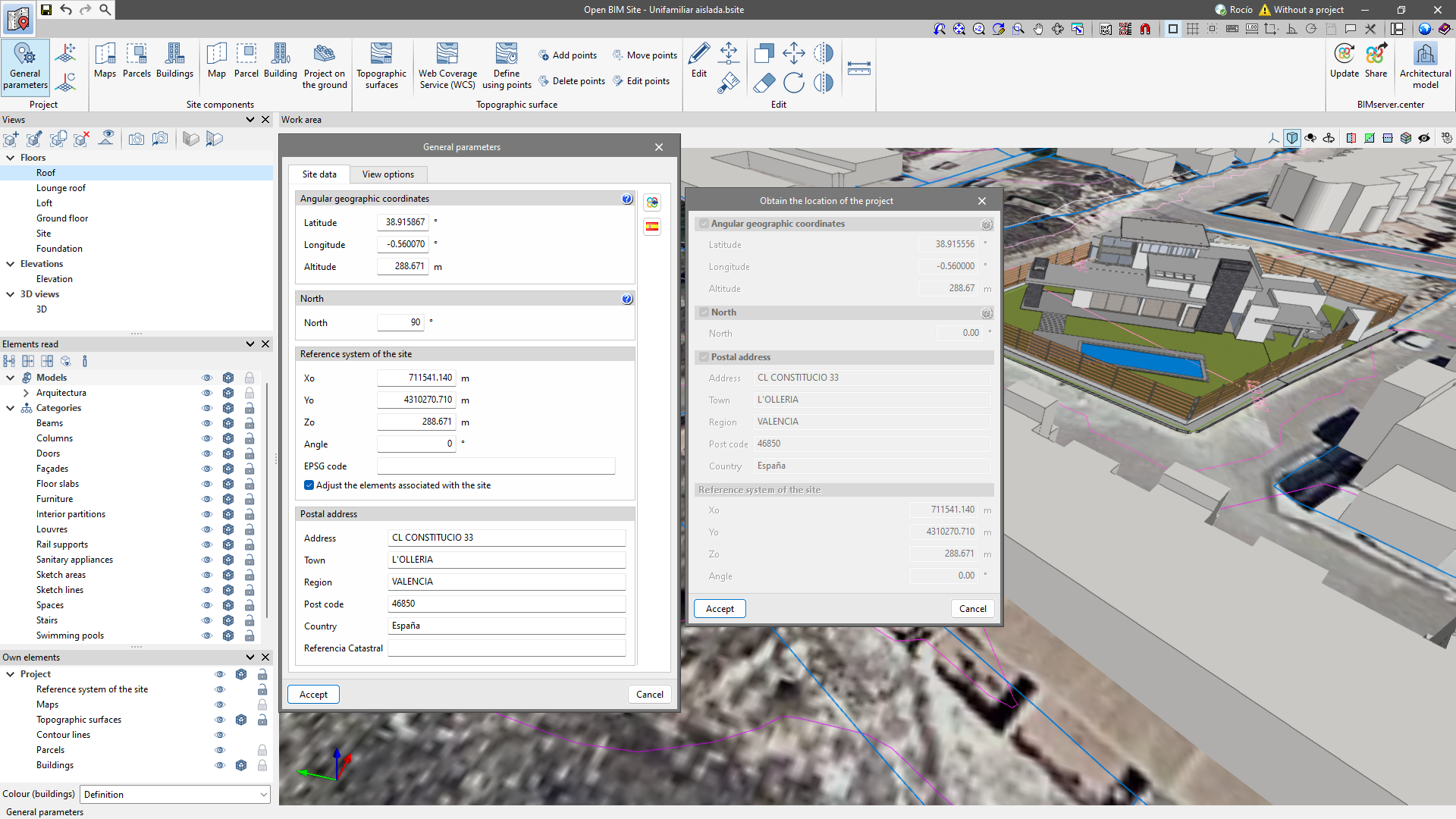
The "EPSG code" and "Cadastral reference" fields have been added to the "General parameters" editing window of the project.
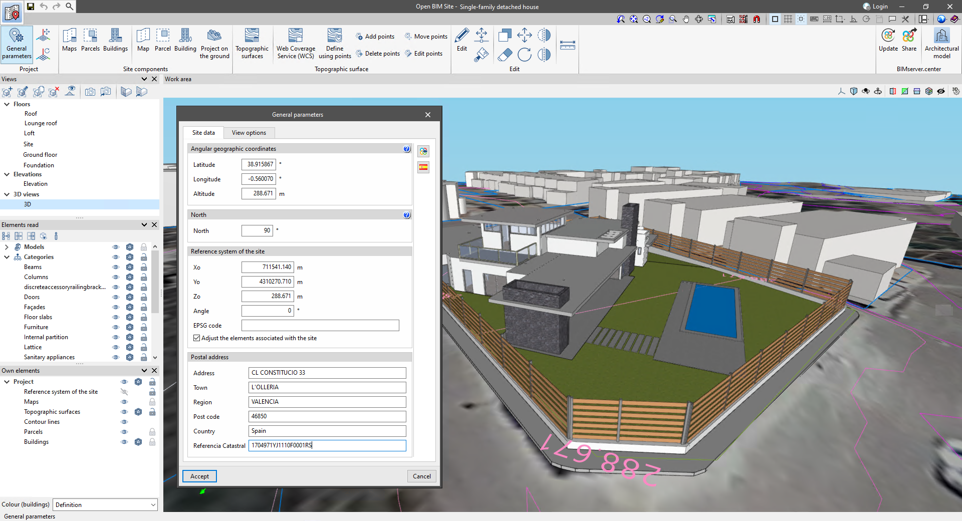
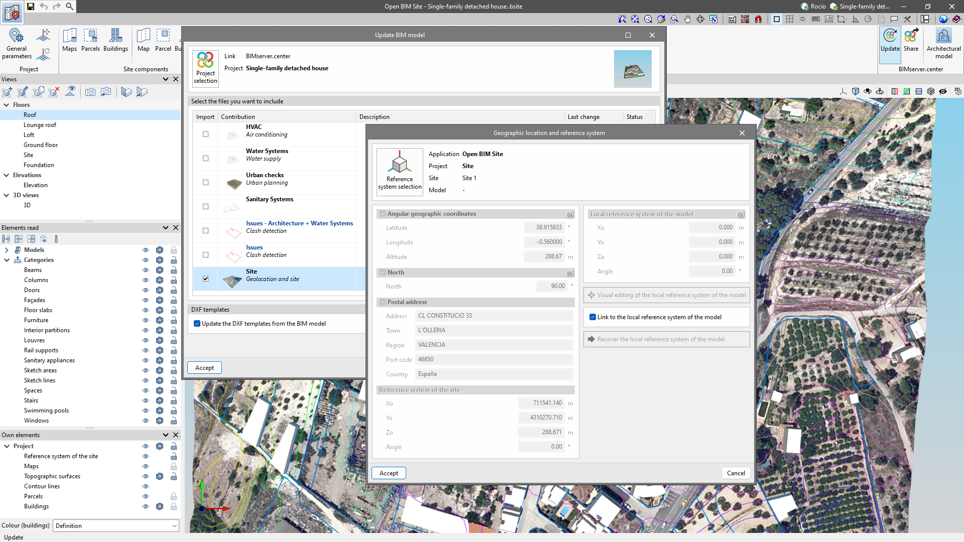
The "Obtain the project site" option has been added to the "General parameters" editing window of the project. With this tool, users can assign the site data of the selected model to the general parameters using the "Geographic location and reference system" option available during the linking or updating of the BIMserver.center project. This makes it easier to work in Open BIM Site with models that already have geolocation data.
In CYPECAD version 2024.e, intermediate supports can now be used between two consecutive spans for ramps.
Like lateral supports, intermediate supports transmit the load to the elements on the floor below or to the elements on the floor above, depending on the support option chosen.
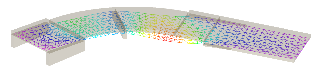
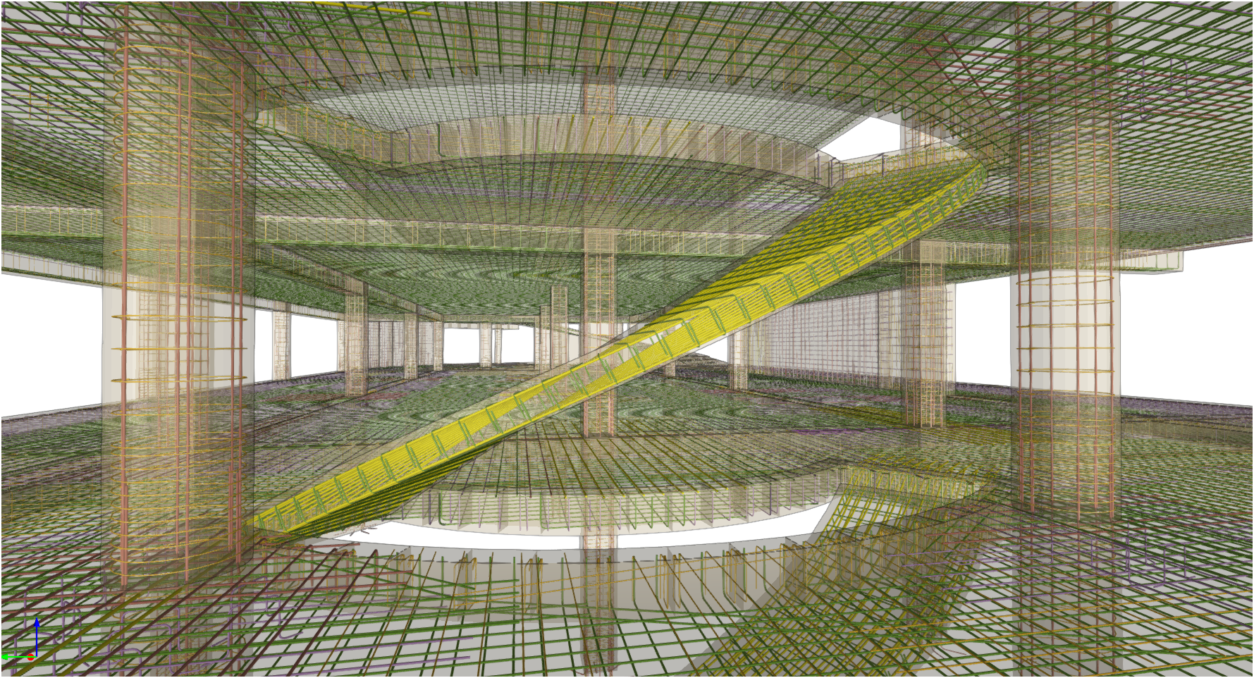
The export of rebars from curved spans of staircases and ramps to the BIM model has been implemented.
In the current version of the program, CYPECAD exports the reinforcement of the following element types:
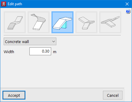
- Concrete walls
- Columns
- Shear walls
- Beam frames
- Staircase
- Ramps
- Foundation elements (footings, pile caps, centring and tie beams)
- Floor slabs (waffle slabs, joist slabs, hollow core slabs, composite slabs and flat slabs)
- Corbels
These rebars can be viewed in StruBIM Rebar, along with rebars exported from the StruBIM Shear Walls program.
They can also be viewed in CYPECAD from the "Results" tab (Groups > 3D view with details).
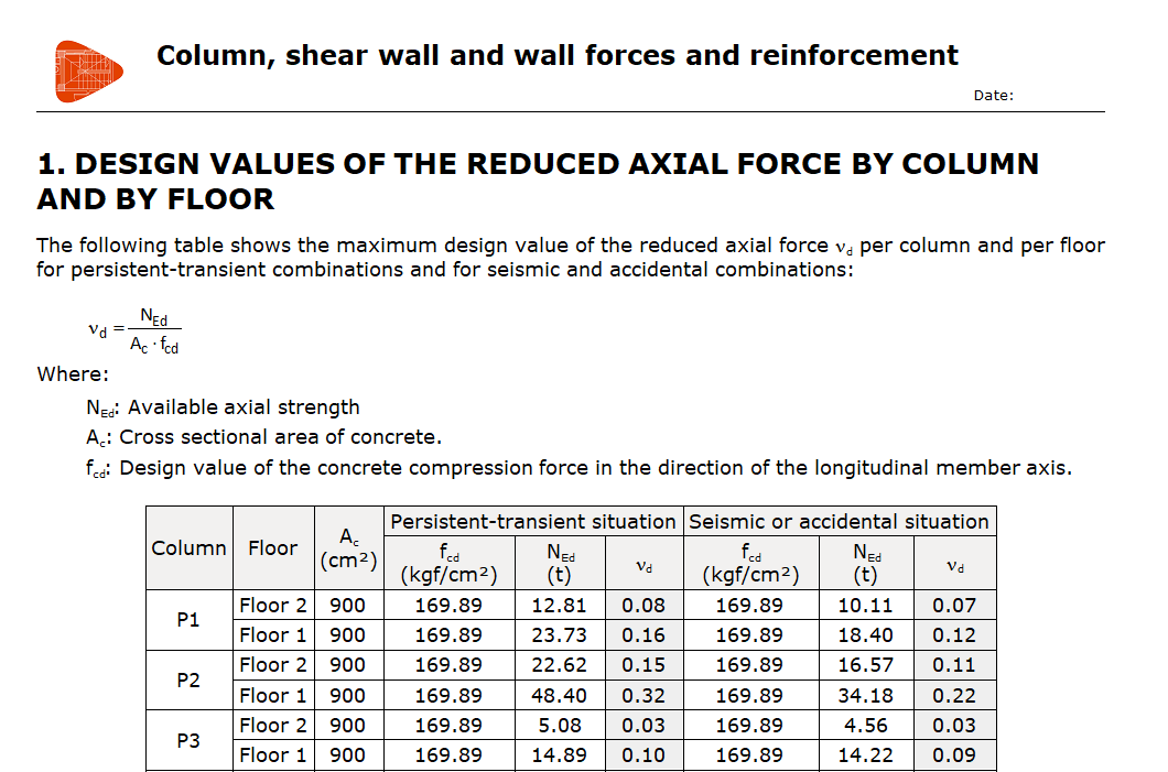
In CYPECAD version 2024.e, in the "Column, shear wall and wall forces and reinforcement" report, the "Design values of the reduced axial force by column and by floor" chapter has been added, which shows the maximum design value of the reduced axial force, for the persistent-transient combinations and the seismic and accidental combinations.
This chapter is enabled for the following standards: Eurocode 2, Spanish structural code "Código Estructural" (Spain), BS-8110 (UK) and NTC (Italy).
CYPECAD version 2024.e includes the following improvements and corrections to the program for some specific cases:
- The editing of project comments (General data > Project comments) has been improved. Previously, the description was plain text. As of version 2024.e, thanks to the new text editor, images can be included and the text can be formatted.
- Now, when a column or a shear wall is moved in the "Column definition" tab, the foundation elements underneath it (pad footings or pile caps) are moved in unison, and this can be seen when selecting the "Beam definition" tab.
- The "Stair options" and "Ramp options" have been improved. Users can now edit the "Specific weight of the fill".
- The definition panel for the generic section of columns that appears when they are entered has been improved. The possibility to enter them by snapping a "DWG/DXF" template has been restored. This option was unintentionally lost due to a change made in previous versions.
- The export of the positive reinforcement of in-situ joists and their 3D visualisation has been improved. The bends of these reinforcements are now displayed correctly. In previous versions, they were displayed as if they were the top reinforcement.
- The export of footings affected by "Limits for polygonal footings" has been improved. Previously, they were exported with the original geometry, now the entered limits are taken into account.
- The export of the reinforcement of caissons and their visualisation in 3D has been improved. Previously, if there was more than one in a pile cap, the reinforcement was not placed at the position of each caisson, but in the centre of the pile cap.
- An error that occurred when importing a job with walls and beams, when no beam had all the necessary information for its import, has been fixed.
- An error that occurred when accessing the panel to generate drawings has been fixed. This error could occur if there were defined metal section columns over a concrete column in the job. This error occurred unintentionally when fixing another error in a previous version.
- The warning that used to appear when any beam overlapped with a foundation element has been removed. This warning prevented the job from being analysed. It is now only displayed if a centring or tie beam is not connected to a foundation element and overlaps with it.
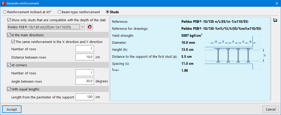
- The interface for selecting shear studs has been improved. Due to improvements made to the Open BIM Database, the way studs are selected has been slightly modified. Previously, studs downloaded from a manufacturer's catalogue and user-defined studs were included in a single library. In the current version, the selection is made independently for "Manufacturer's catalogues" or "User punching shear studs". Furthermore, the "Generate reinforcement" panel has been simplified.
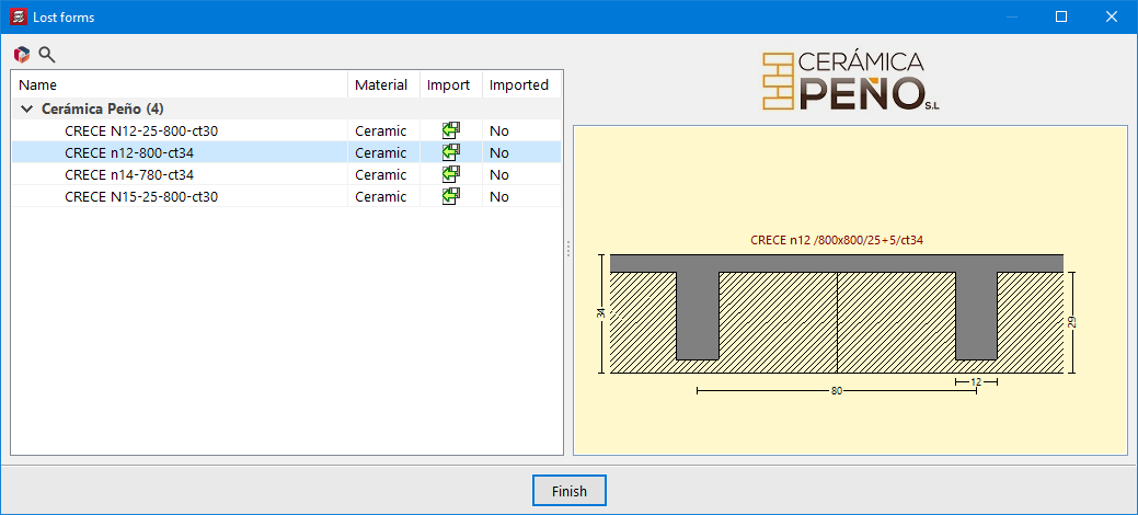
- The interface for selecting waffle slab forms when entering this panel type has been improved. Due to improvements made in the Open BIM Database, the way users select forms from manufacturers' catalogues and the user library has been slightly modified. Several forms can now be imported from a manufacturer's catalogue or a library without having to enter the selection panel as many times as the number of forms to be imported into the project.
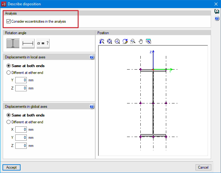
Up until version 2024.e, the eccentricities defined in bars from "Bar > Describe disposition" always affected the design model.
As of version 2024.e, users can now choose whether or not to take eccentricities into account in the analysis.
When the option is not activated in a bar, this bar is considered to be centred in the design model.
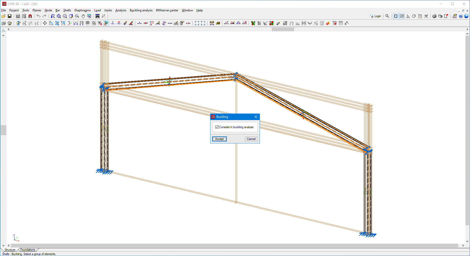
As of version 2024.e, users can now analyse the buckling behaviour of shells. To do this, the "Buckling" option has been included in the "Shells" menu.
With this option, the shells to be considered in the linear buckling analysis can be marked.
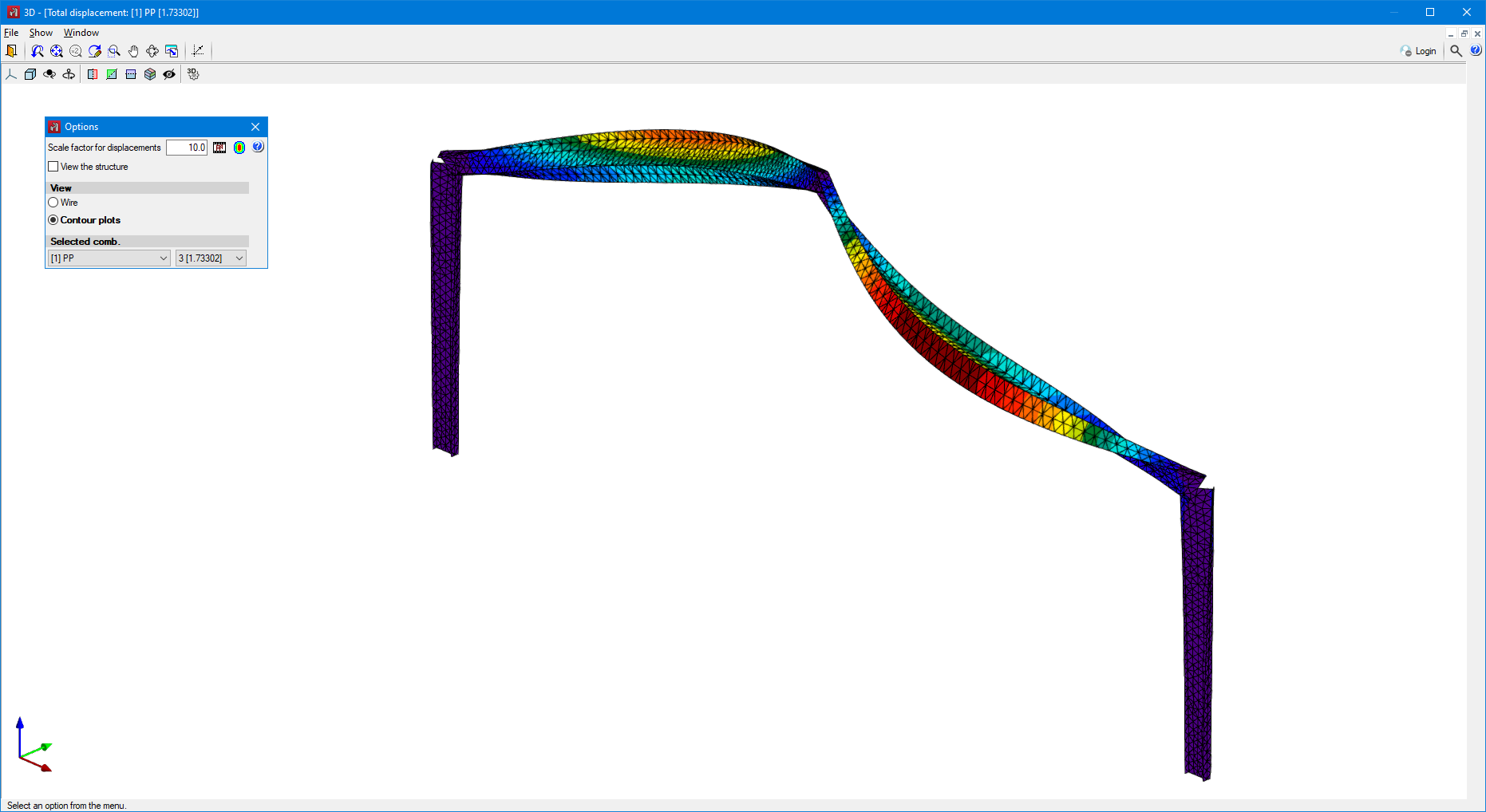
Also, in the "Buckling analysis" menu, the "Buckling contour plots of the active window" option has been added.
Once the buckling analysis has been carried out, this option allows users to view the contour plots of the deformed shape in the different modes.
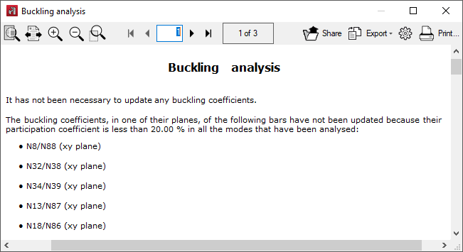
Up until version 2024.e, when buckling coefficients were assigned, bars that did not participate in any buckling mode were assigned a buckling coefficient equal to zero.
As of version 2024.e a warning will be displayed, after the buckling coefficient assignment process, and the buckling coefficients of the bars that do not have a participation percentage higher than the minimum percentage in all analysed modes will not be updated.
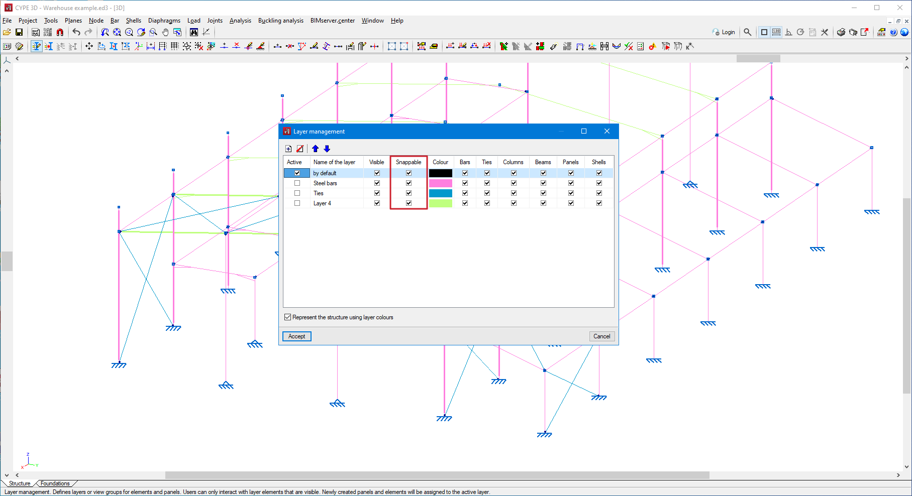
As of version 2024.e, users can now select whether the elements of each layer are snappable or non-snappable.
In "Layer management" the "Snappable" column has been added.
When this option is unchecked in any layer, the elements belonging to that layer cannot be snapped.
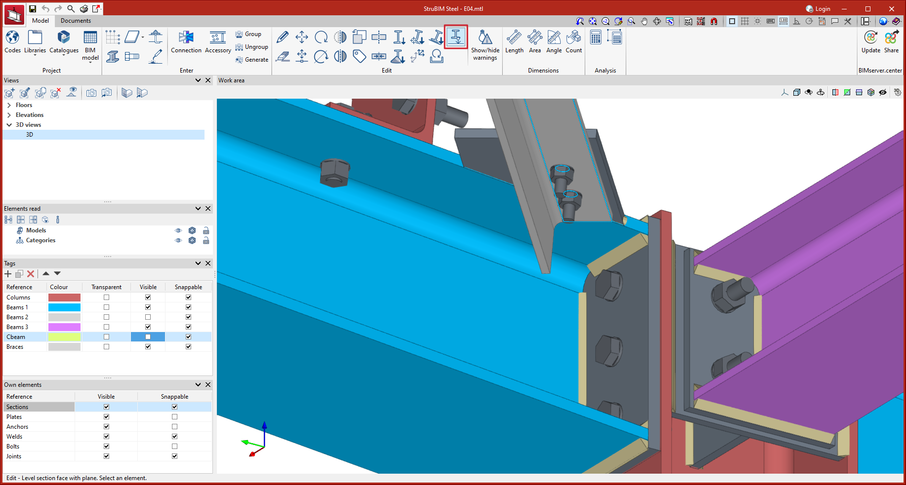
In version 2024.e, a new tool has been implemented that allows users to move sections until one of their faces is level with the face of another element.
First of all, the sections to be moved are selected by clicking the left mouse button on the reference face, and the right mouse button is used to finish the selection.
Next, users must select the parallel face of another element with the left mouse button, to which the selected sections will be levelled.
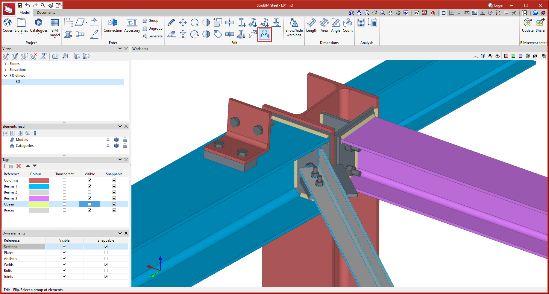
In StruBIM Steel version 2024.e, a tool for flipping sections about their longitudinal axis has been implemented.
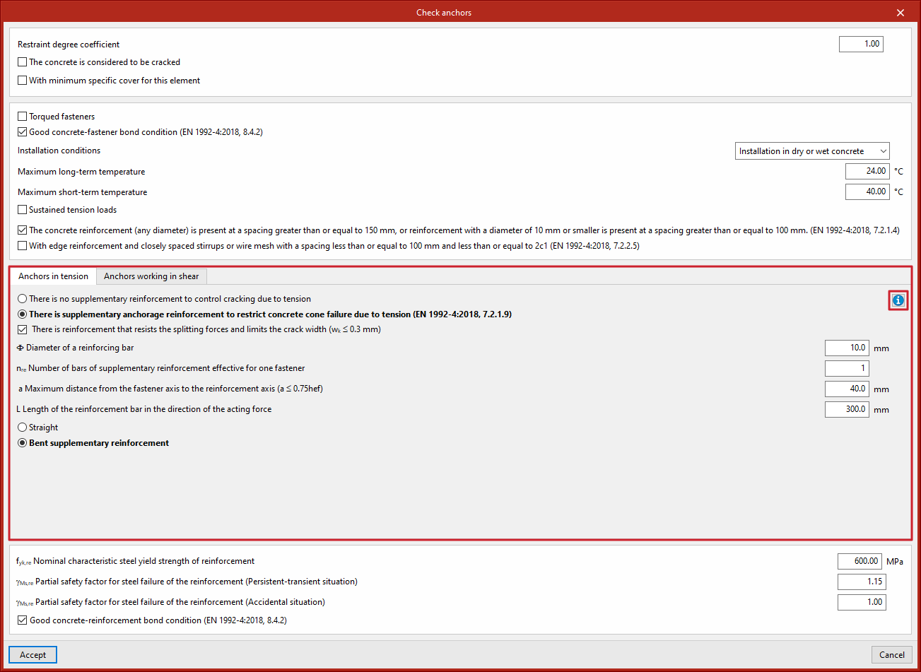
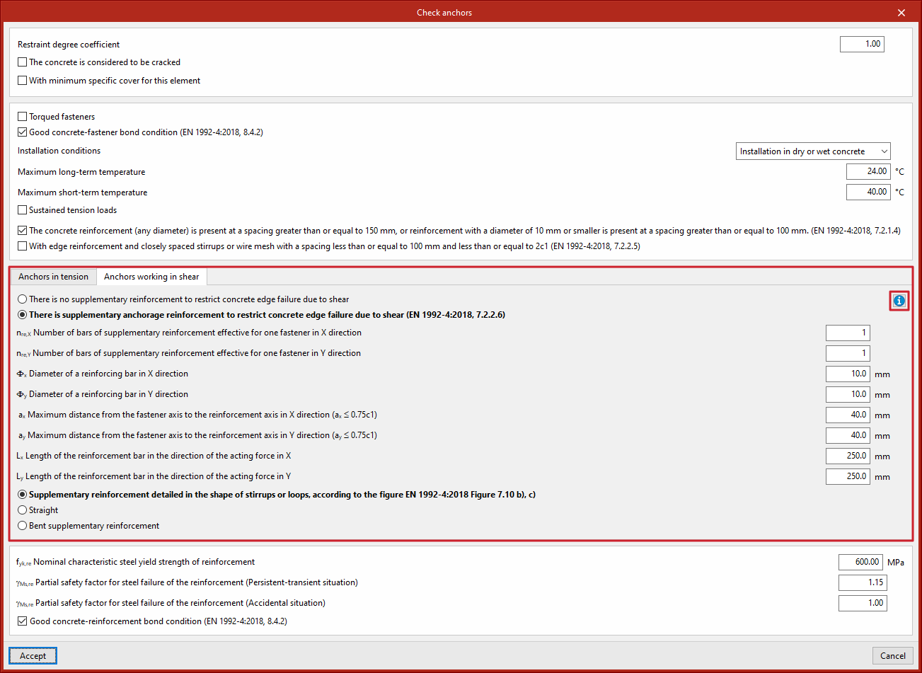
In version 2024.e of CYPE Connect and StruBIM Steel, the panel where the parameters are entered when creating the supplementary reinforcements associated with anchors has been improved. New options have been added to simplify the panel, also, graphic aids with texts have been implemented to help users understand the available options in greater detail.
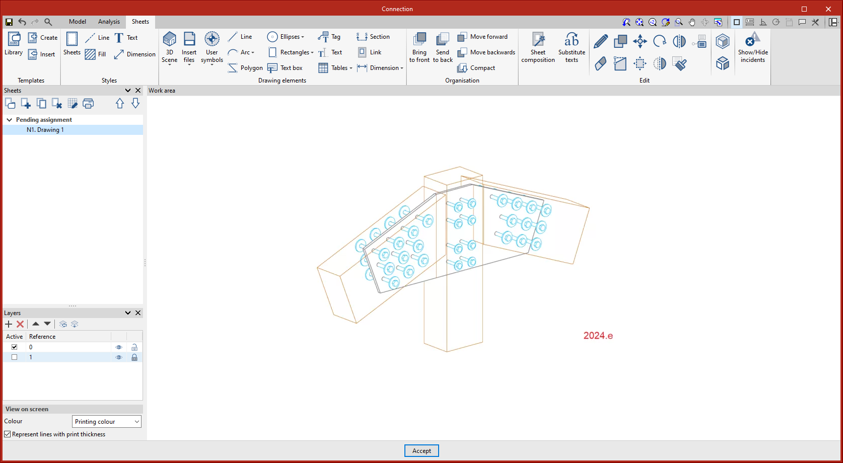
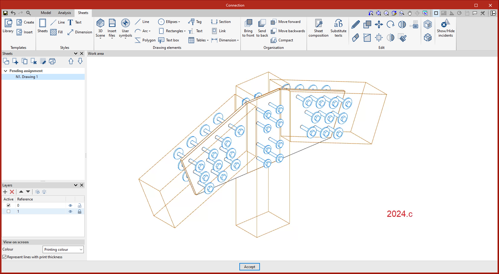
As of version 2024.e, elements with a wire drawing mode will show only the visible lines, hiding the lines that would be hidden if the model were drawn solid.
As of version 2024.e, CYPE Connect and StruBIM Steel can also be installed in Chinese and Turkish. These two applications can now be installed in the following languages:
- Catalan
- Chinese
- English
- French
- German
- Italian
- Japanese
- Polish
- Portuguese
- Romanian
- Russian
- Spanish
- Turkish
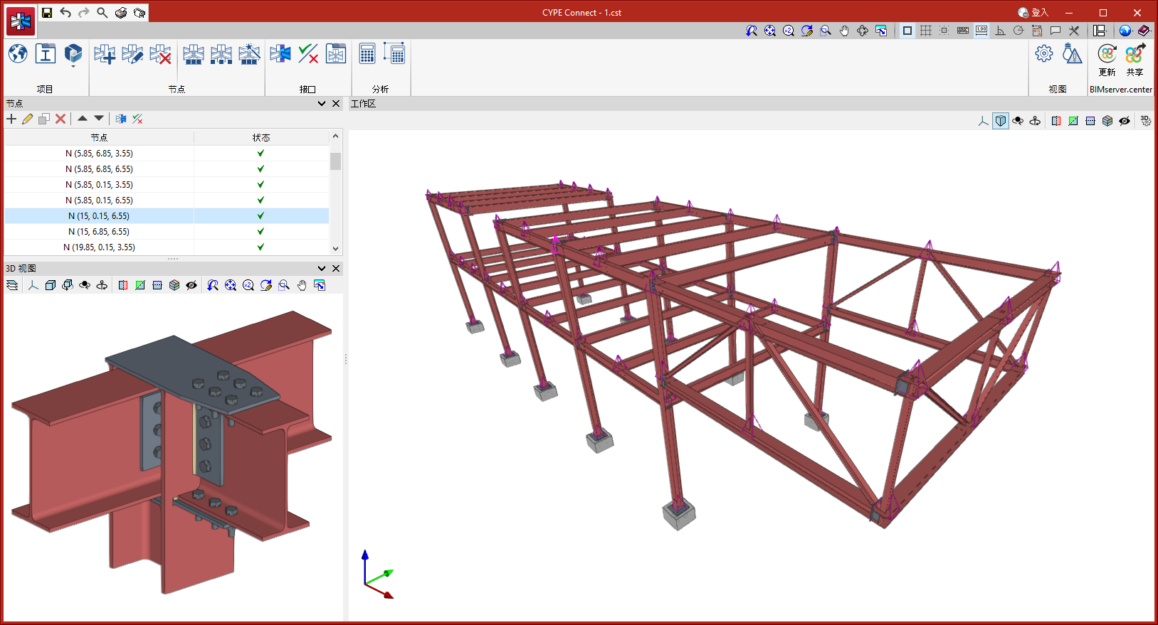
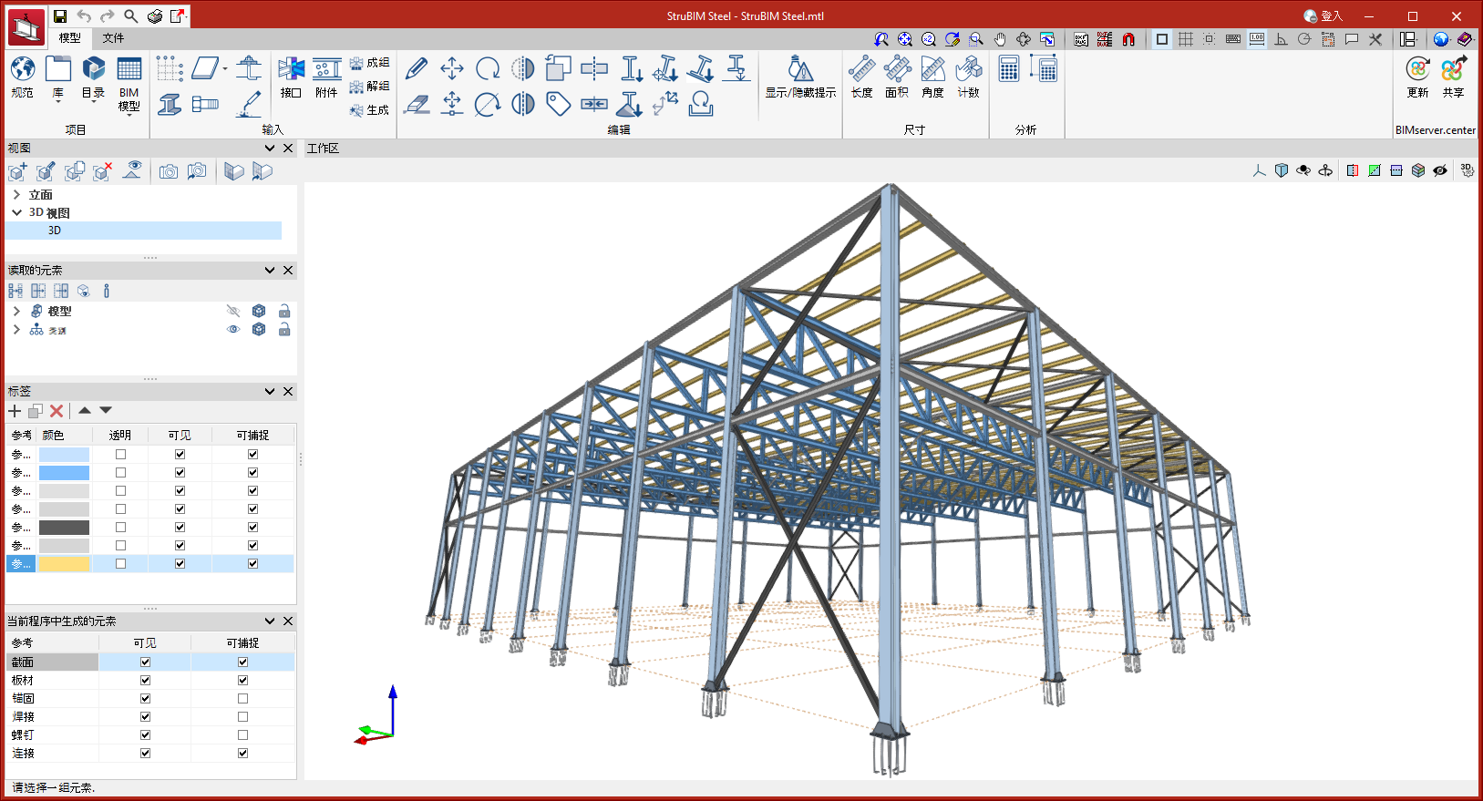
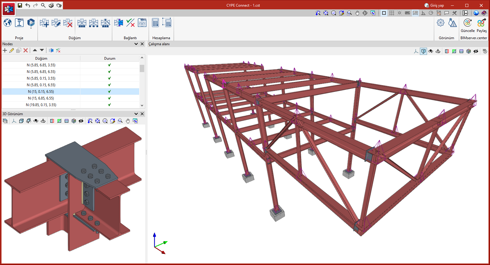
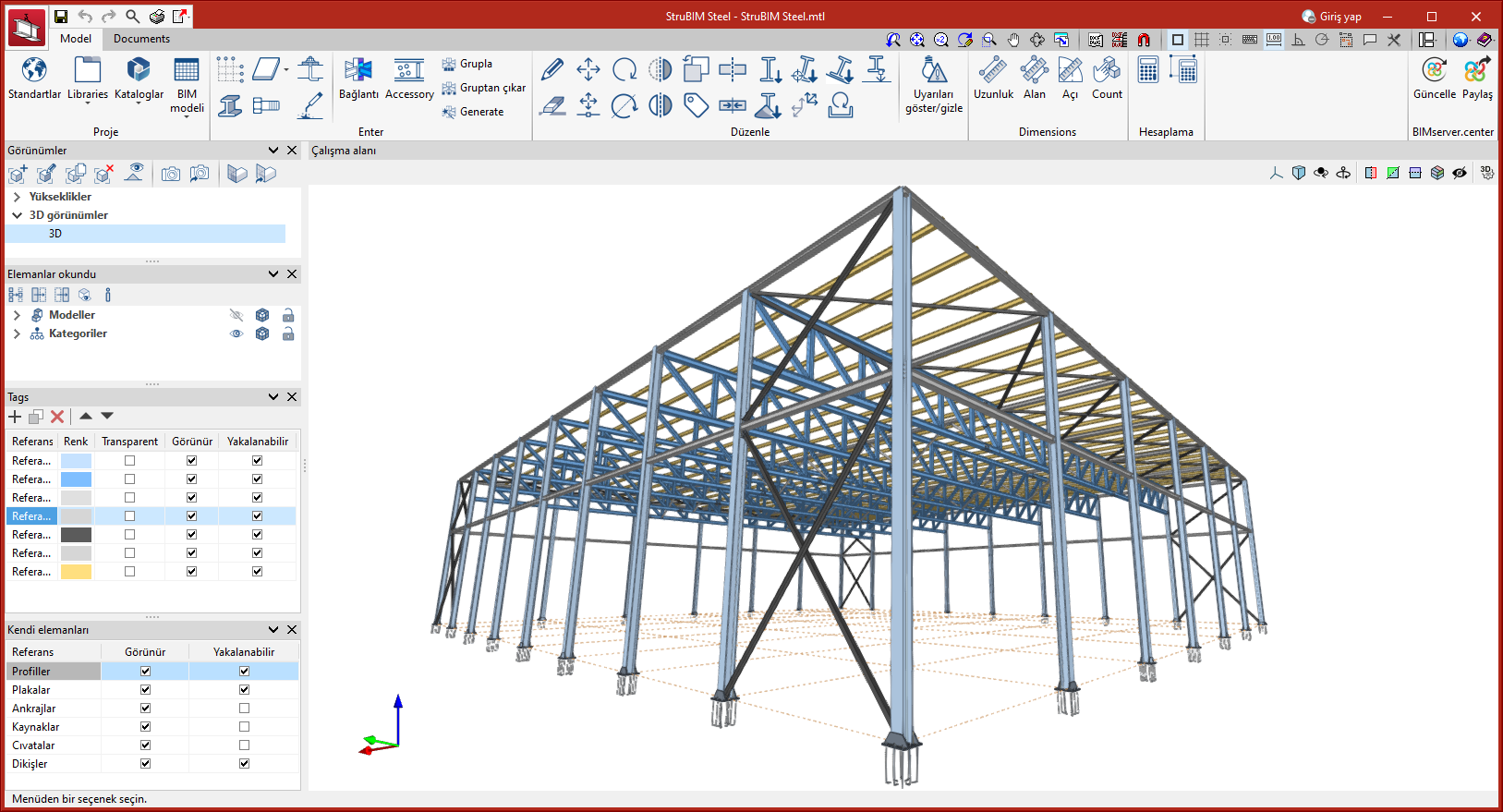
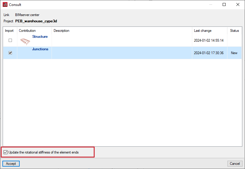
Version 2024.e implements the export of the rotational stiffnesses of the connections in CYPE Connect and StruBIM Steel. The import of rotational stiffnesses is also implemented in CYPE 3D.
This improvement allows the rotational stiffness of connections analysed in CYPE Connect or StruBIM Steel to be considered in the original CYPE 3D structure.
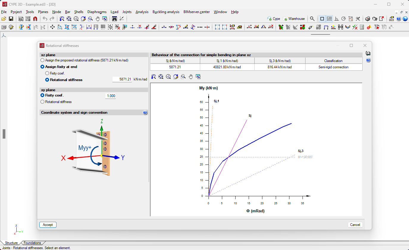
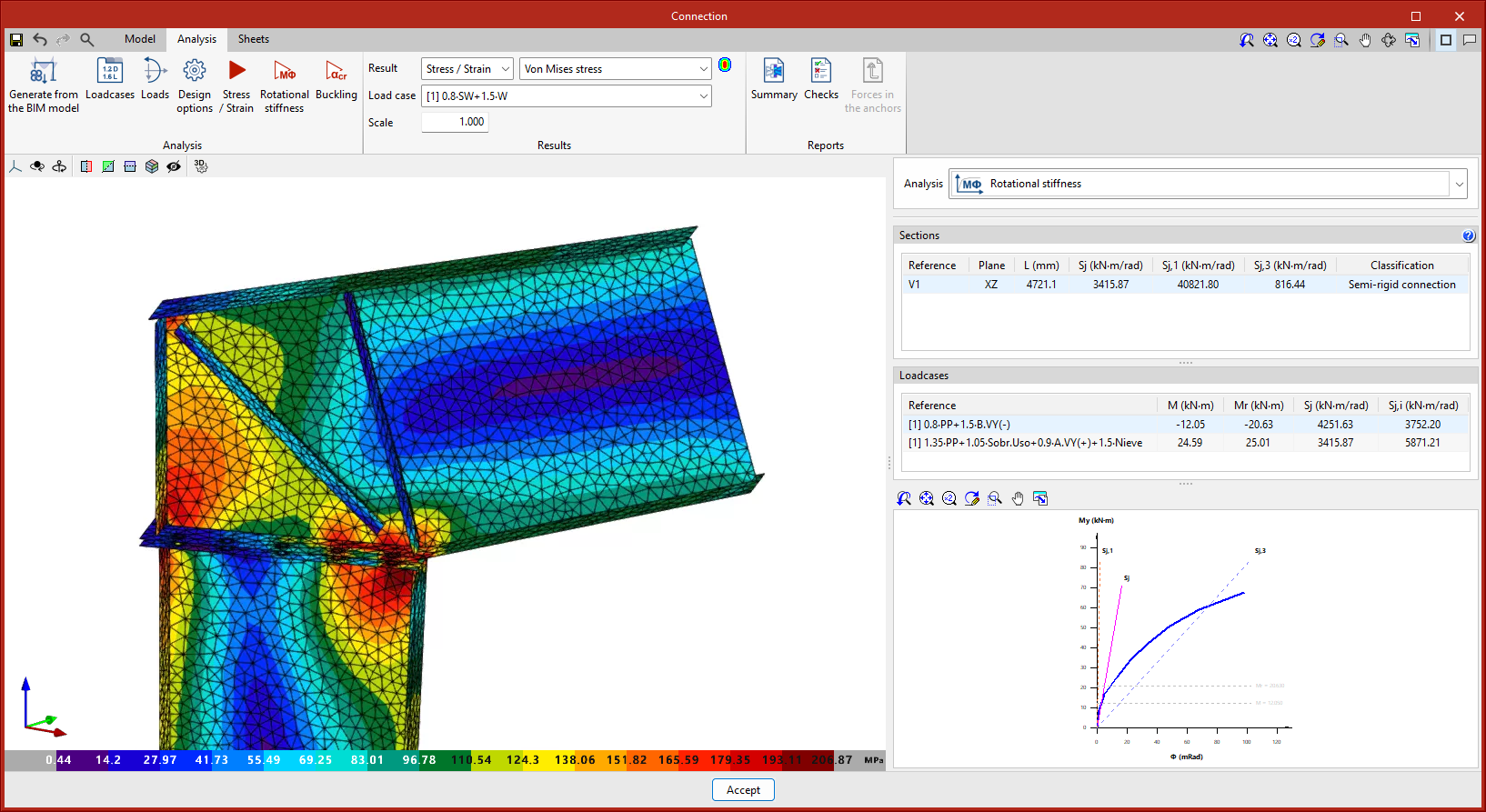
The export occurs when there are connections with analysed rotational stiffness and is exported to BIMserver.center.
In CYPE 3D, the corresponding contribution must be imported from the menu "BIMserver.center > Consult", activating the "Update the rotational stiffness of the element ends" option.
As of version 2024.e, Open BIM Cable Routing can also be installed in Portuguese. The languages in which this application can be installed are now: Catalan, English, Portuguese and Spanish.
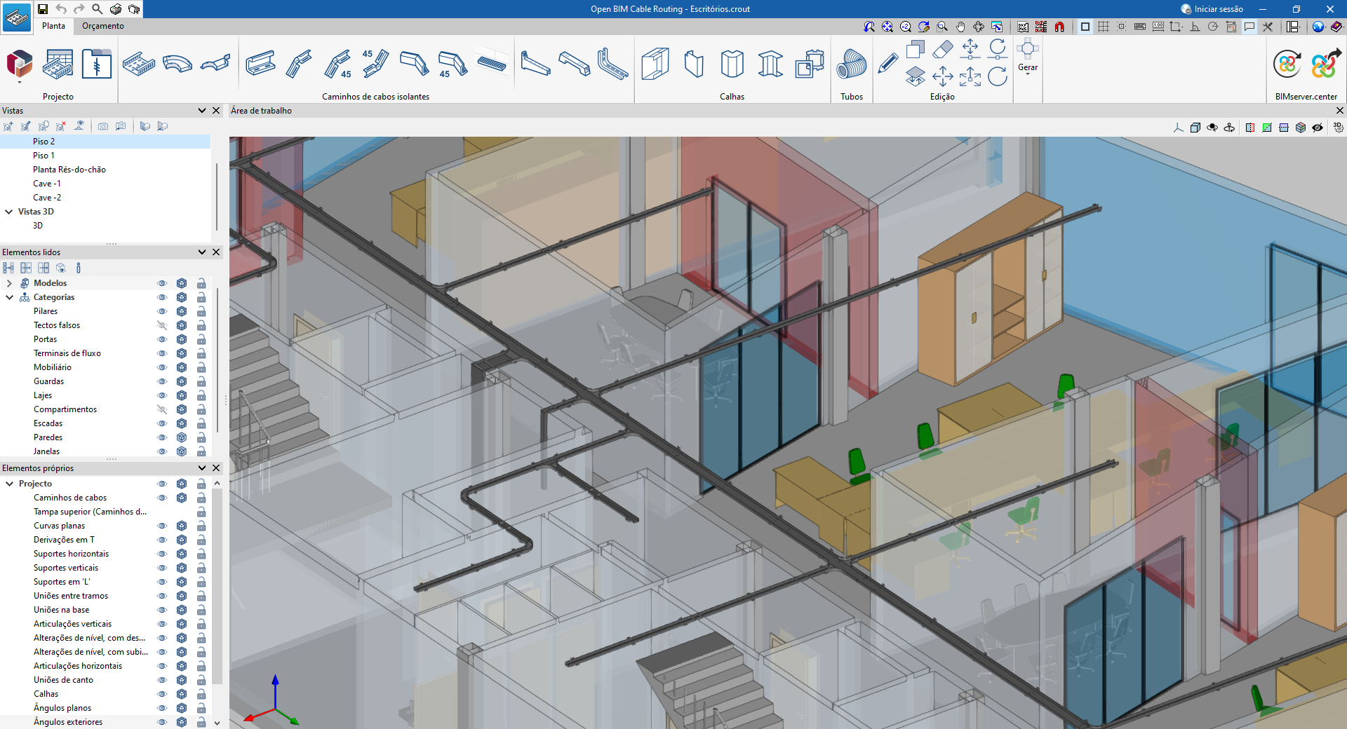
A new example job, "Residential building", is included, showing the design of a cable tray system in a building with 18 dwellings.
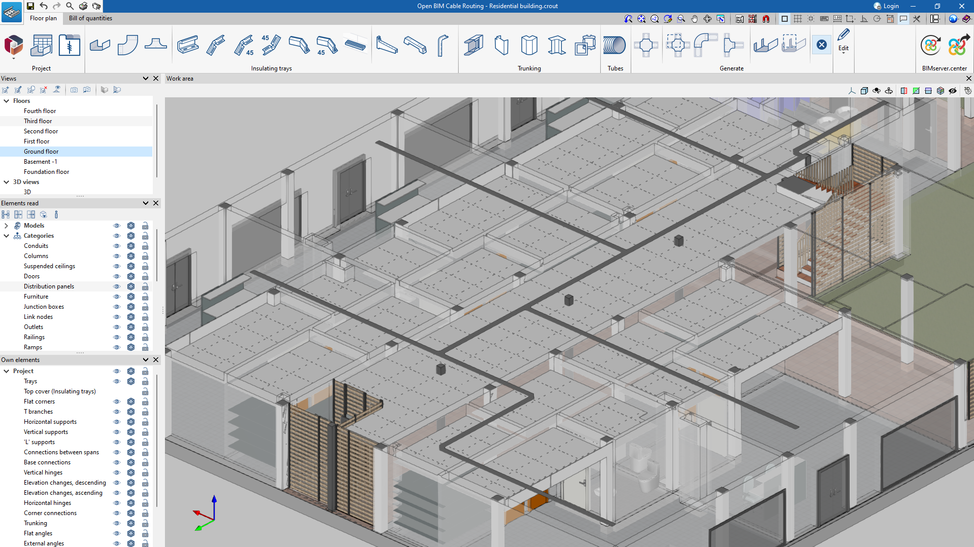
The polarity selection on supply lines and intermediate lines has been extended.
The new polarity options have the particular feature of not distributing the neutral conductor.
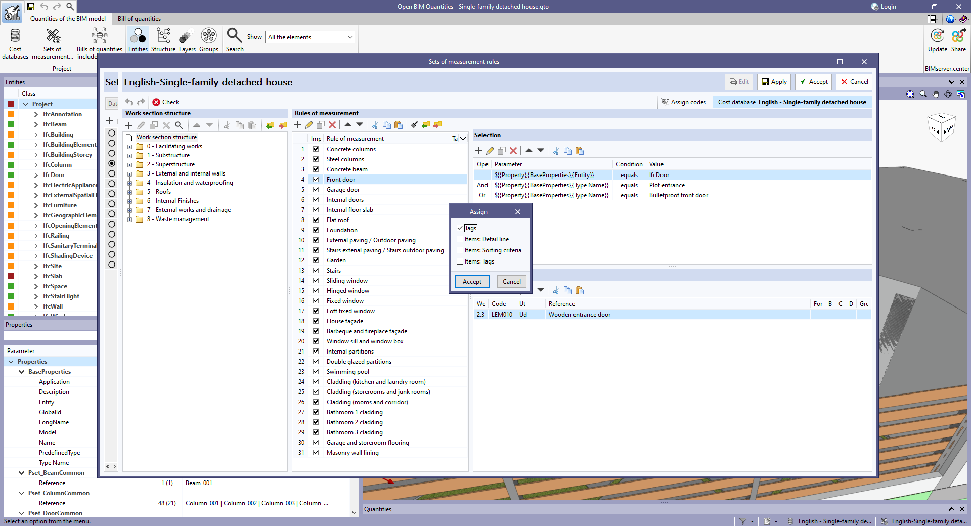
The "Assign" option has been added to the options bar of the "Rules of measurement" list in the "Sets of measurement rules" editing window.
With this tool, users can assign the properties from one rule of measurement to another.
Clicking the "Assign" option displays a window with a list of the properties of the selected rule that can be assigned. The following properties are currently available to choose from:
- Tags
- Items: Detail line
- Items: Sorting criteria
- Items: Tags
Once the fields have been selected, a new window is displayed with the list of rules of measurement where users can select those rules whose properties are to be modified with the values of the previously selected rule. This way, with version 2024.e, users can edit multiple measurement rules defined within the same set.
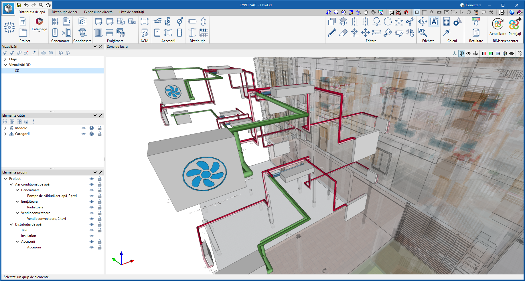
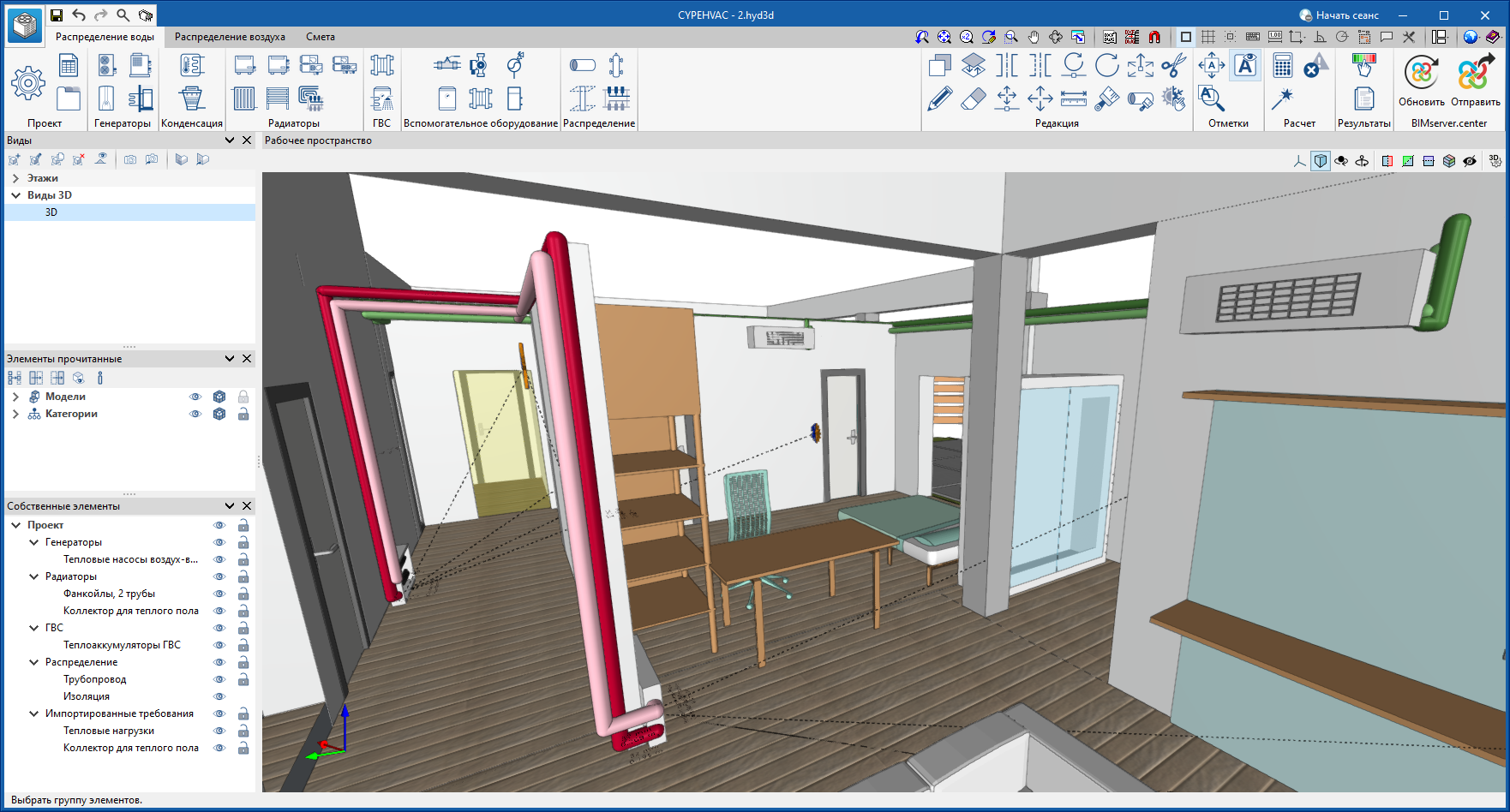
As of version 2024.e, CYPEHVAC can also be installed in Romanian and Russian. The languages in which this application can now be installed are the following:
- Catalan
- English
- French
- Italian
- Polish
- Portuguese
- Romanian
- Russian
- Spanish