As of version 2024.f, plastic hinges can now be inserted into bars.
Using the new "Plastic hinges" option in the "Bar" menu, the relative position of the plastic hinges and their properties can be defined, as well as the rotational degrees of freedom in which they act.
Considering plastic hinges in the design of a structure requires a non-linear analysis using the OpenSees analysis engine. Therefore, users must have permission to use this analysis engine in their license, together with the "Plastic hinges" module.
More information on this CYPE 3D module can be found in the "Plastic hinges (new module)" new feature.
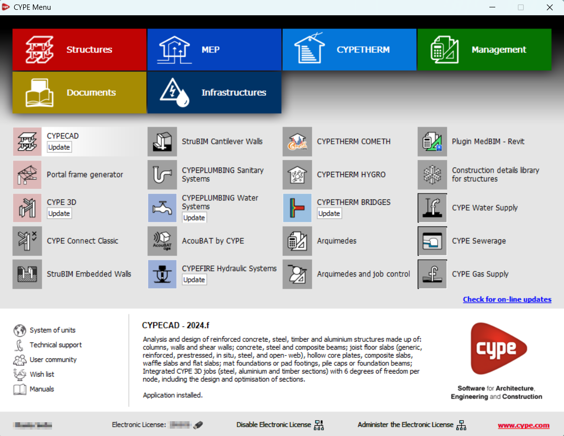
As of version 2024.f, the CYPE Menu tool (available on the BIMserver.centre platform Store) allows users to manage the updates of the applications it includes.
When accessing the CYPE Menu, the program checks whether there is a newer version of the installed applications and, if so, the "Update" option appears next to them.
The update process will download the application and, once completed, will start the installation.
CYPE Architecture version 2024.f includes a new feature that allows windows, doors and skylights to be drawn freely, thus increasing the program possibilities for drawing carpentry. This new feature, together with the new feature of the previous version (2024.e) for creating Carpentry drawings, makes the program more efficient when designing and drawing carpentry and its corresponding drawings.
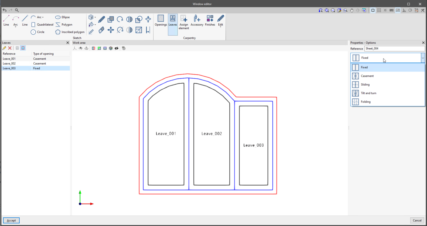
This new feature can be accessed from the types panel. When creating a new type, such as windows, the "Window editor" option can now be selected.
Carpentry editing (windows, doors and skylights) follows the same drawing logic used by CYPE Architecture with the sketch/architecture duality, to benefit from the advantages offered by the sketch drawing when defining the carpentry.
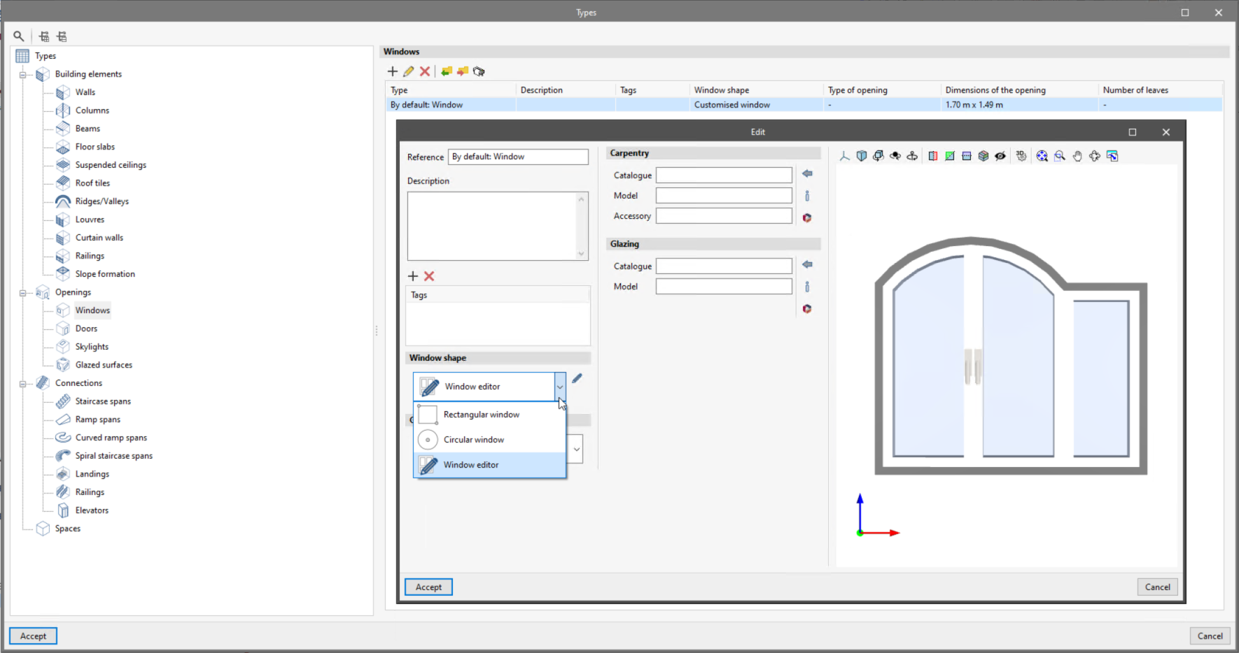
For this reason, the toolbar has been divided into two groups "Sketch" and "Carpentry".
Sketch
The "Sketch" group contains all the tools available for modelling the carpentry freely.
Carpentry
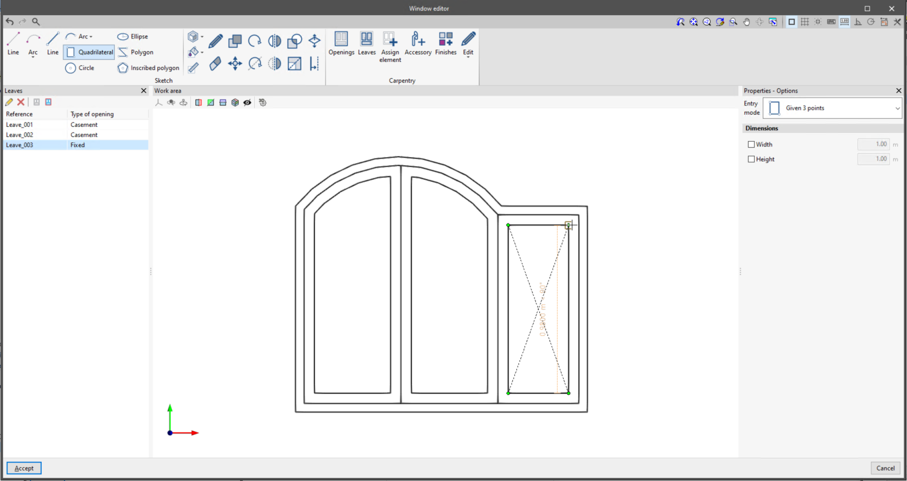
The options in the "Carpentry" section allow users to enter the elements specific to each type (door, window or skylight), based on the sketch drawing.
First of all, the perimeter of the opening and the leaves are defined using sketch lines. At the same time, the type of opening for the leaves can be selected during this process.
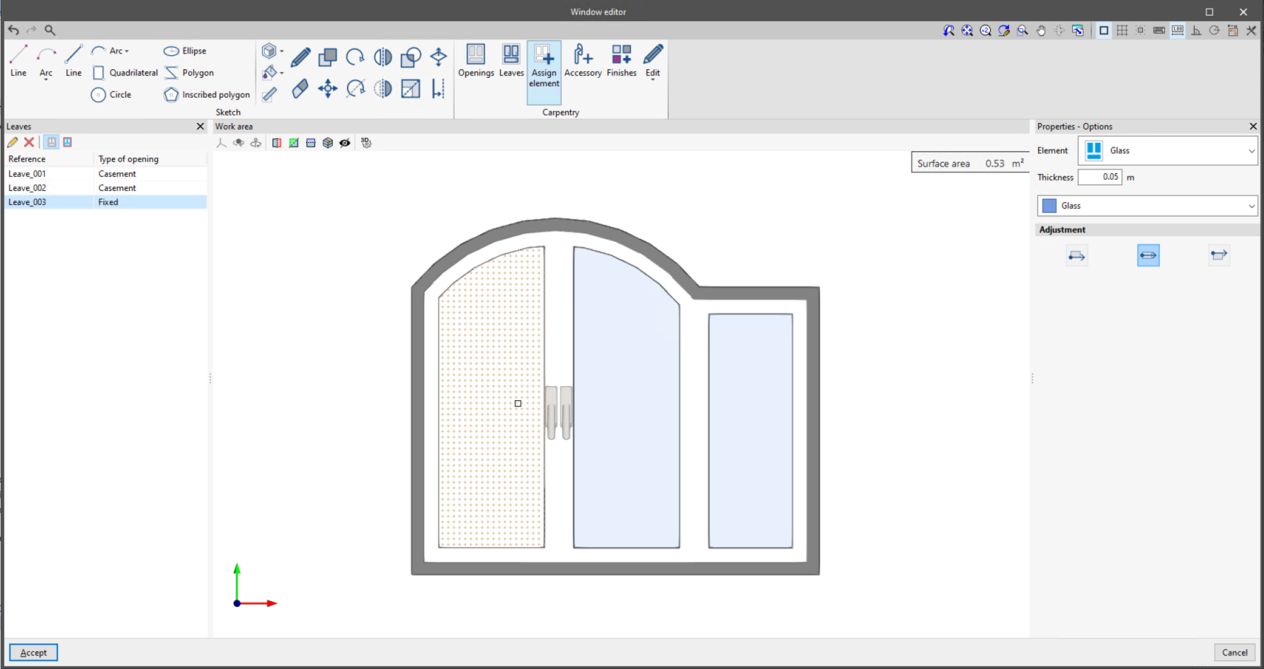
Secondly, carpentry elements must be defined: opening frames, leaf frames, glass, opaque surfaces, blind boxes, windowsills or decorative elements, by selecting sketch surfaces. It is also possible to enter accessories such as window handles or door knobs.
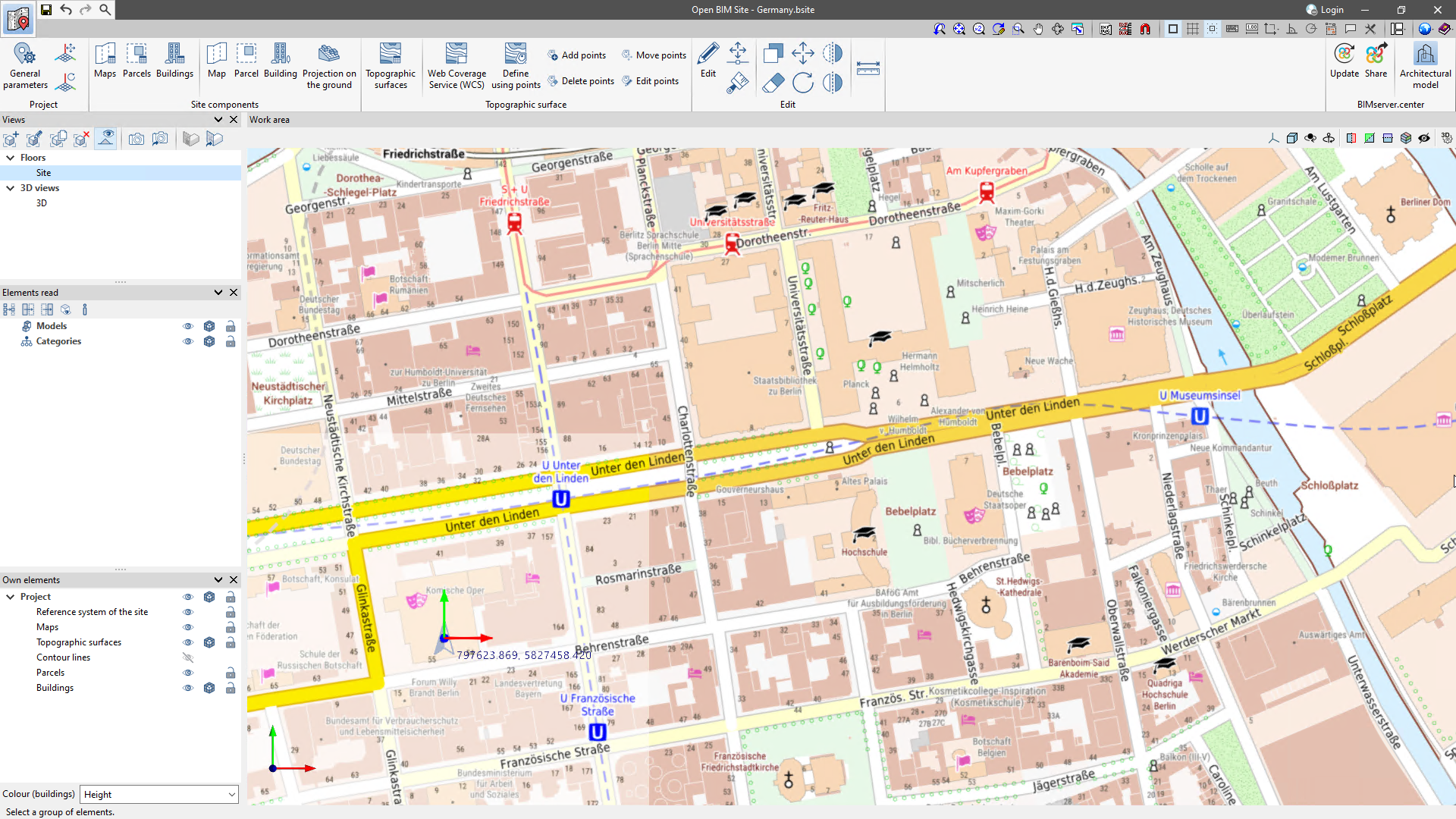
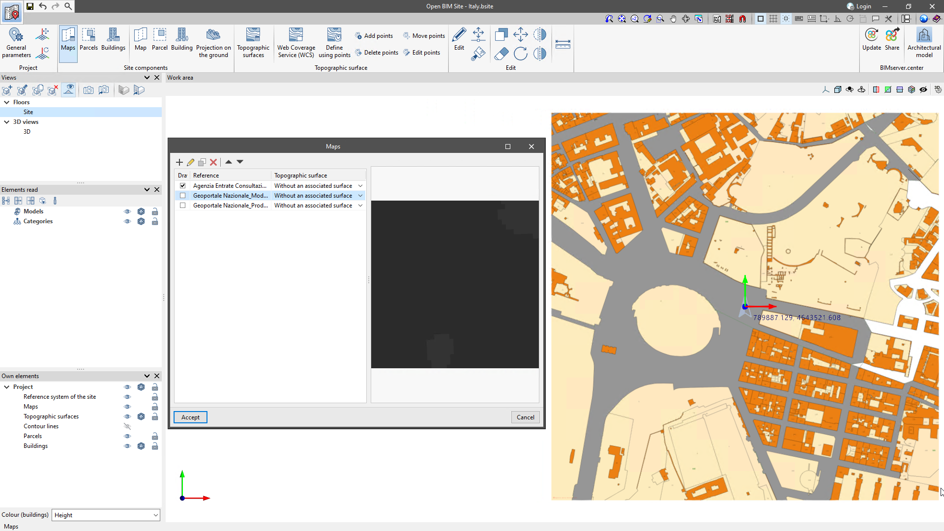
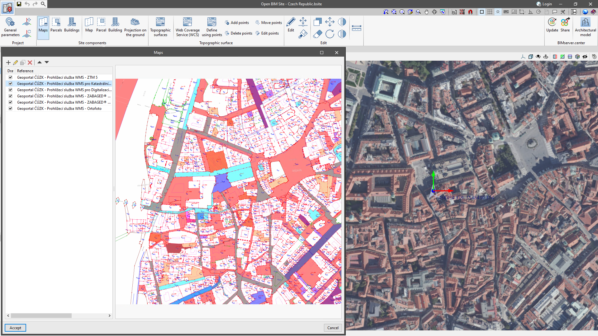
As of version 2024.f, Open BIM Site allows users to obtain maps via WMS services from the following data sources:
- Poland
- Ortofotomapa standardowa
- Ortofotomapa standardowa
- Germany
- Bundesamt für Kartographie und Geodäsie - TopPlusOpen
- Präsentationsgraphik 1:5 000
- Italy
- Geoportale Nazionale_Modello digitale del terreno - 20 metri
- Agenzia Entrate Consultazione cartografia catastale
- Geoportale Nazionale_Prodotti LiDAR - Area Dolomitica
- Geoportale Nazionale_Prodotti LiDAR - Provincia di Bolzano
- Geoportale Nazionale_Prodotti LiDAR - Regione Abruzzo
- Geoportale Nazionale_Prodotti LiDAR - Regione Basilicata
- Geoportale Nazionale_Prodotti LiDAR - Regione Calabria
- Geoportale Nazionale_Prodotti LiDAR - Regione Campania
- Geoportale Nazionale_Prodotti LiDAR - Regione Emilia Romagna
- Geoportale Nazionale_Prodotti LiDAR - Regione Friuli Venezia Giulia
- Geoportale Nazionale_Prodotti LiDAR - Regione Lazio
- Geoportale Nazionale_Prodotti LiDAR - Regione Liguria
- Geoportale Nazionale_Prodotti LiDAR - Regione Lombardia
- Geoportale Nazionale_Prodotti LiDAR - Regione Marche
- Geoportale Nazionale_Prodotti LiDAR - Regione Molise
- Geoportale Nazionale_Prodotti LiDAR - Regione Piemonte
- Geoportale Nazionale_Prodotti LiDAR - Regione Puglia
- Geoportale Nazionale_Prodotti LiDAR - Regione Sardegna
- Geoportale Nazionale_Prodotti LiDAR - Regione Sicilia
- Geoportale Nazionale_Prodotti LiDAR - Regione Toscana
- Geoportale Nazionale_Prodotti LiDAR - Provincia di Trento
- Geoportale Nazionale_Prodotti LiDAR - Regione Umbria
- Geoportale Nazionale_Prodotti LiDAR - Regione Valle d'Aosta
- Geoportale Nazionale_Prodotti LiDAR - Regione Veneto
- Czech Republic
- Geoportal ČÚZK - Prohlížecí služba WMS - ZTM 5
- Geoportal ČÚZK - Prohlížecí služba WMS pro Katastrální mapu (KM)
- Geoportal ČÚZK - Prohlížecí služba WMS pro Digitalizaci katastrální mapy (DG)
- Geoportal ČÚZK - Prohlížecí služba WMS - ZABAGED® - polohopis
- Geoportal ČÚZK - Prohlížecí služba WMS - ZABAGED® - vrstevnice
- Geoportal ČÚZK - Prohlížecí služba WMS - Ortofoto
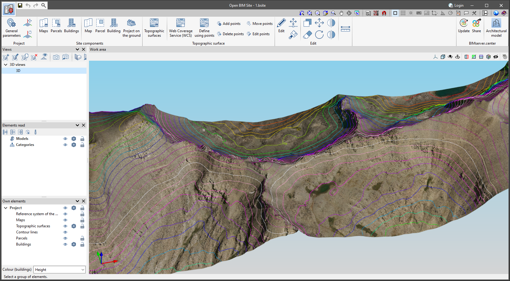
As of version 2024.f, Open BIM Site can save transformations that have been made on topographic surfaces.
In this way, when topographic surfaces come from WCS web services, they can be updated without losing any displacements or rotations made using the application's editing tools.
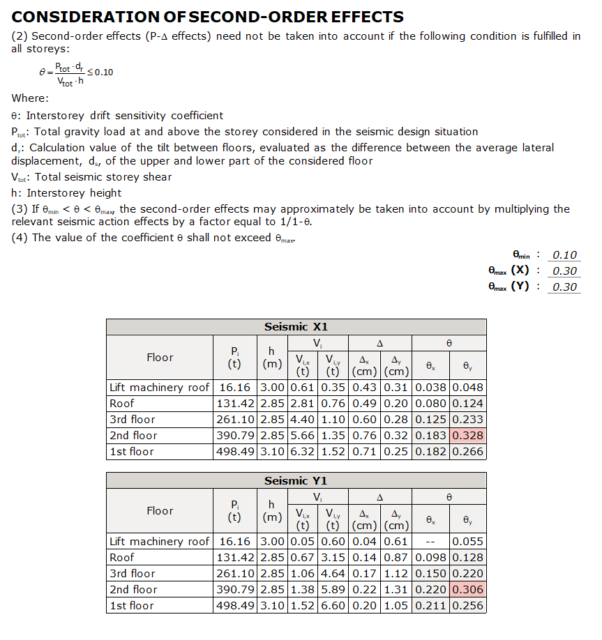
As of version 2024.f, CYPECAD generates the new "Consideration of second-order effects" report, which analyses whether P-Delta effects are to be taken into account in the analysis.
For this purpose, the stability coefficient or sensitivity coefficient (θ) is calculated per floor and per analysis direction for each seismic loadcase.
When the stability coefficient (θ) is lower than the minimum limit value (θmin), second-order effects can be neglected.
If the coefficient θ is between the minimum and maximum limit values set, θmin < θ ≤ θmax, second-order effects must be considered.
This can be simplified by considering the P-Delta effects, amplifying the effects of the seismic action. If the coefficient θ is higher than the maximum limit (θmax), the structure is potentially unstable and must be stiffened.
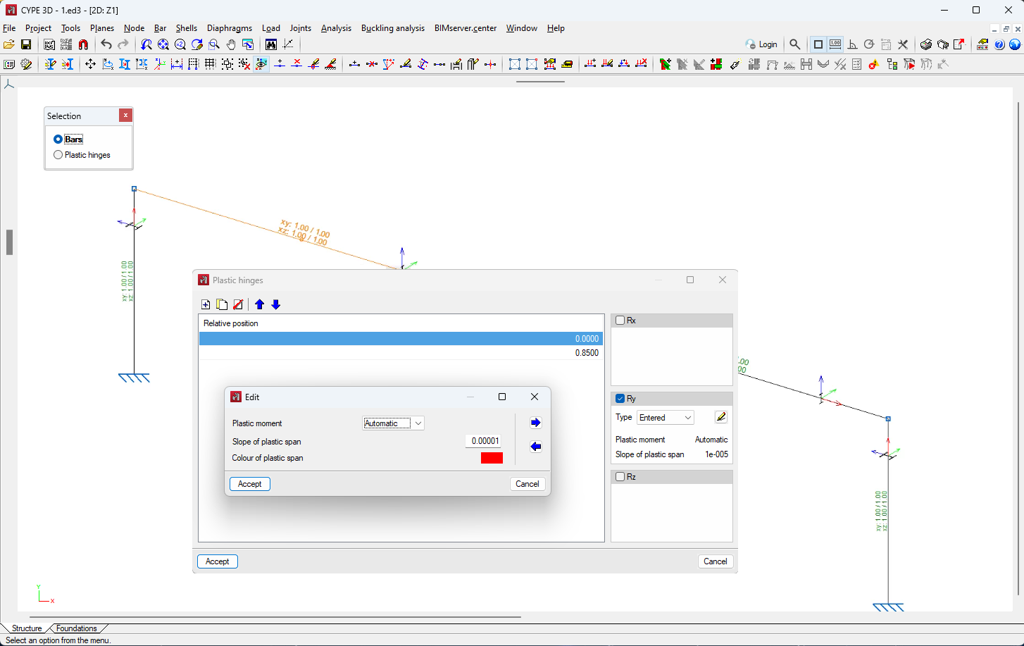
As of version 2024.f, CYPE 3D has a new module that allows plastic hinges to be inserted in bars.
Considering plastic hinges in the design of a structure requires a non-linear analysis using the OpenSees analysis engine. Therefore, users must have permission to use this analysis engine in their license, together with the "Plastic hinges" module.
Using the new "Plastic hinges" option in the "Bar" menu, the relative position of the plastic hinges and their properties can be defined, as well as the rotational degrees of freedom in which they act.
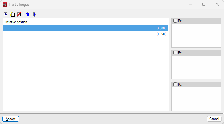
The data required to define the behaviour of a plastic hinge at a given rotational degree of freedom are the plastic moment and the slope in the plastic section. The degrees of freedom are expressed in the local axes of the bar.
The properties of the hinge can be selected from those previously defined in the "Plastic hinge library" in the "Project" menu or entered directly in the plastic hinge definition panel.
The program can automatically analyse the value of the plastic moment for steel sections with a defined plastic modulus. In all other cases, this value can be defined manually.
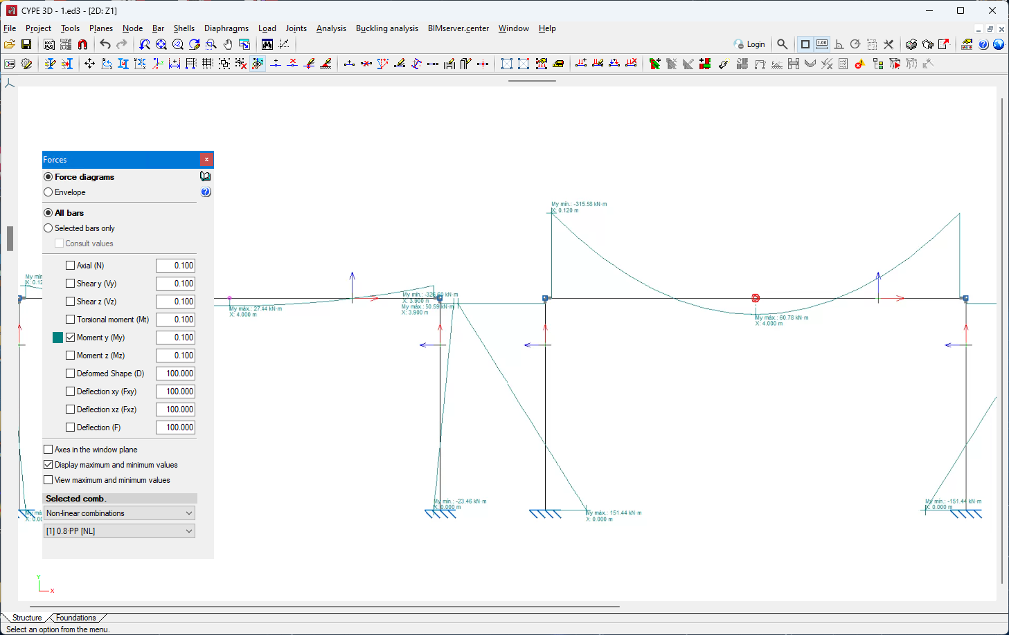
In the forces view, the plastic hinges that have reached the plastic moment in the selected combination are highlighted by an increase in size and a colour change.
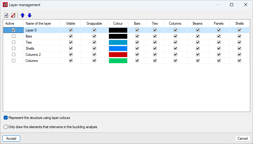
Up until version 2024.f each element, panel or shell could be assigned to a single layer. As of version 2024.f each element can belong to several layers.
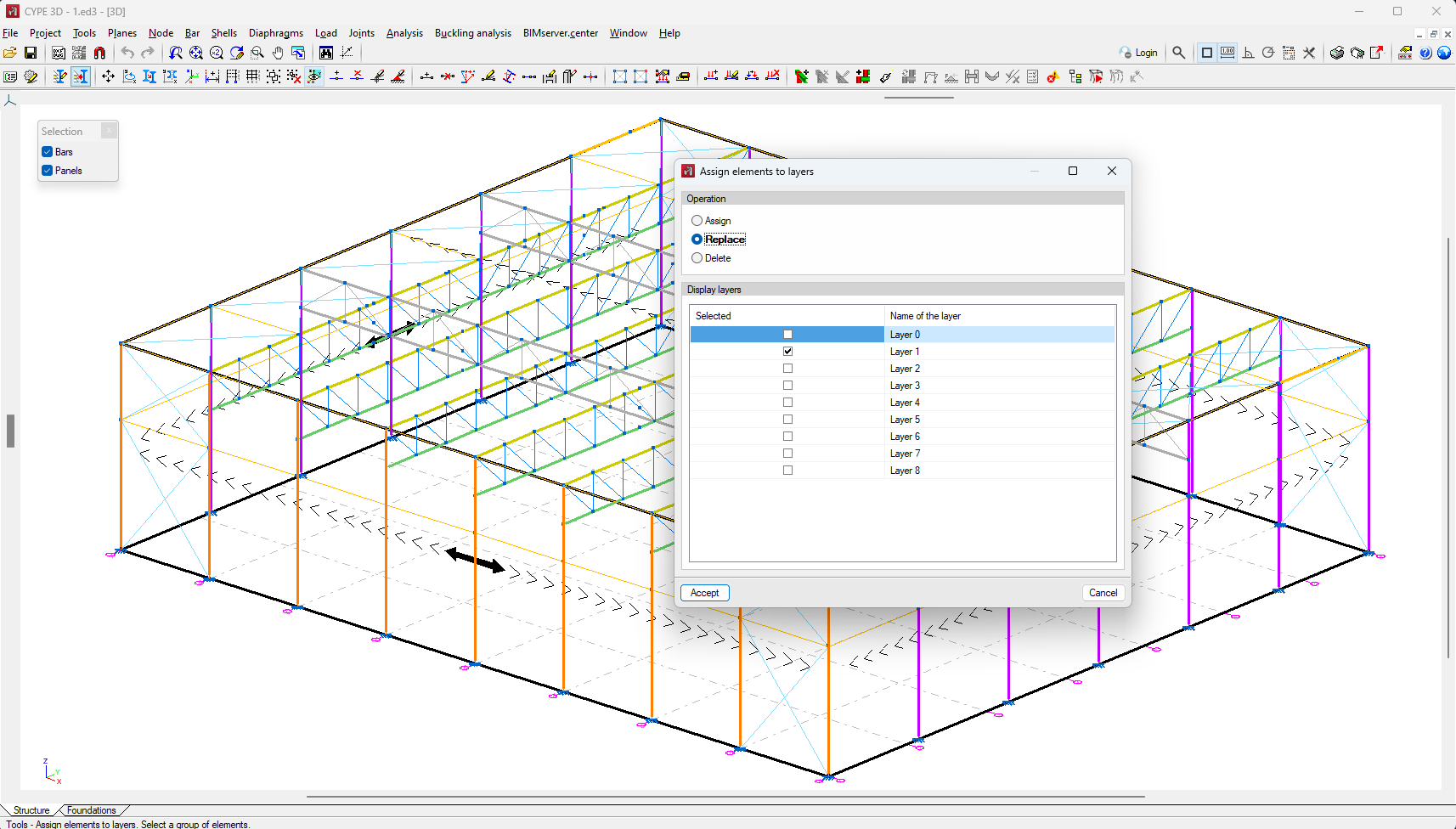
The tools for assigning parts, panels and shells to layers are unified in "Assign elements to layers". This tool allows you to select the type of operation and the display layers. The available operations are the following:
- Assign
Adds the selected layers to the elements. - Replace
Replaces the previously assigned layers with the newly selected layers. - Delete
Deletes the selected layer from the previous assignment of each layer.
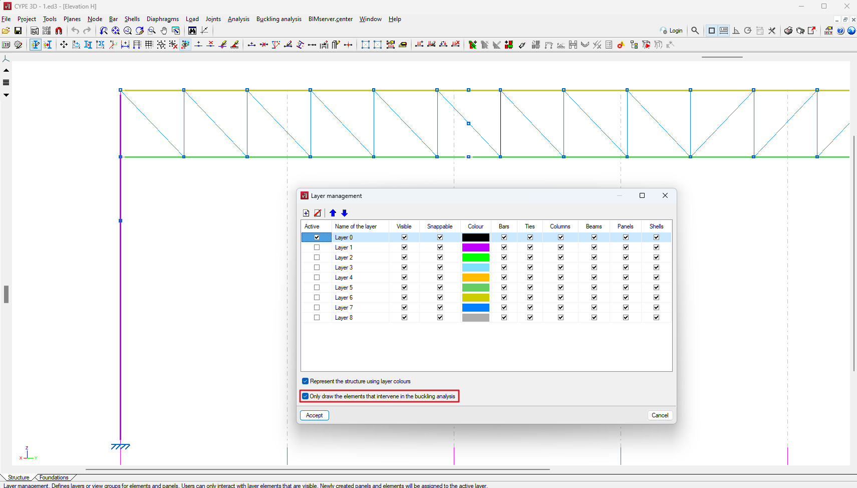
In layer management, the "Only draw the elements that intervene in the buckling analysis" option is included.
As of version 2024.f of CYPE 3D, users can define buckling analysis groups to independently analyse the buckling behaviour of different sets of elements in the structure.
Groups are defined using the "Analysis groups" option in the "Buckling analysis" menu and are based on the layers defined and assigned to the different elements of the structure using the "Assign elements to layers" option in the "Tools" menu. You can consult this version's new feature, Layer management, which describes the improvements implemented in assigning layers to elements since they allow the use of layers as a previous step to define buckling analysis groups.
In the buckling analysis of each of the groups, all the elements marked with the "Consider in buckling analysis" option (Bar menu > "Buckling" option) and which also have one of the layers selected in the definition of the group assigned to them will be considered.
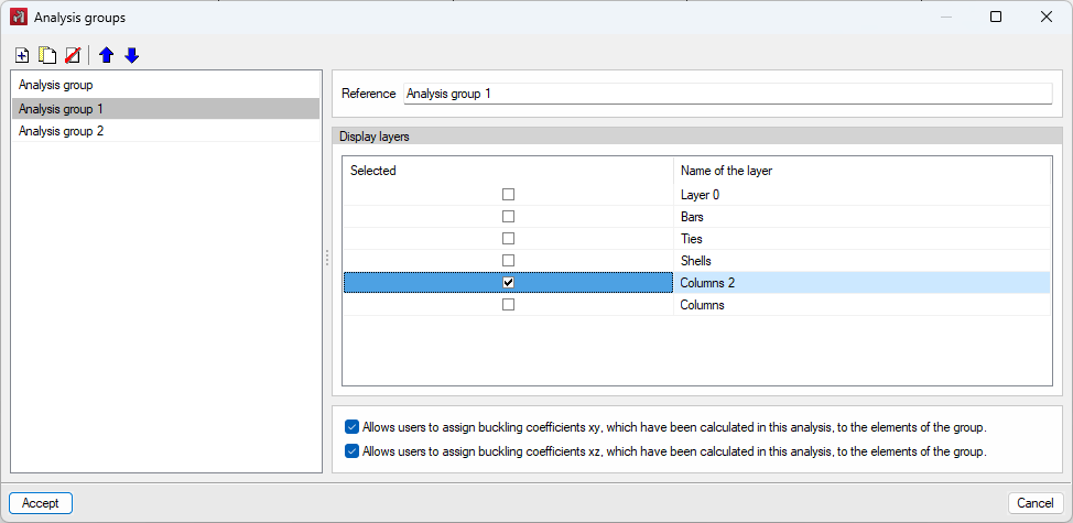
The consideration of groups for the analysis is optional. If no group is entered, the program will perform a single analysis considering all the bars and plates marked with the "Consider in buckling analysis" option. If a bar belongs to more than one group and an automatic assignment of its buckling coefficient in the xy, xz or both planes is carried out, it will be assigned the highest of all the coefficients analysed in the buckling analyses of the groups to which it belongs.
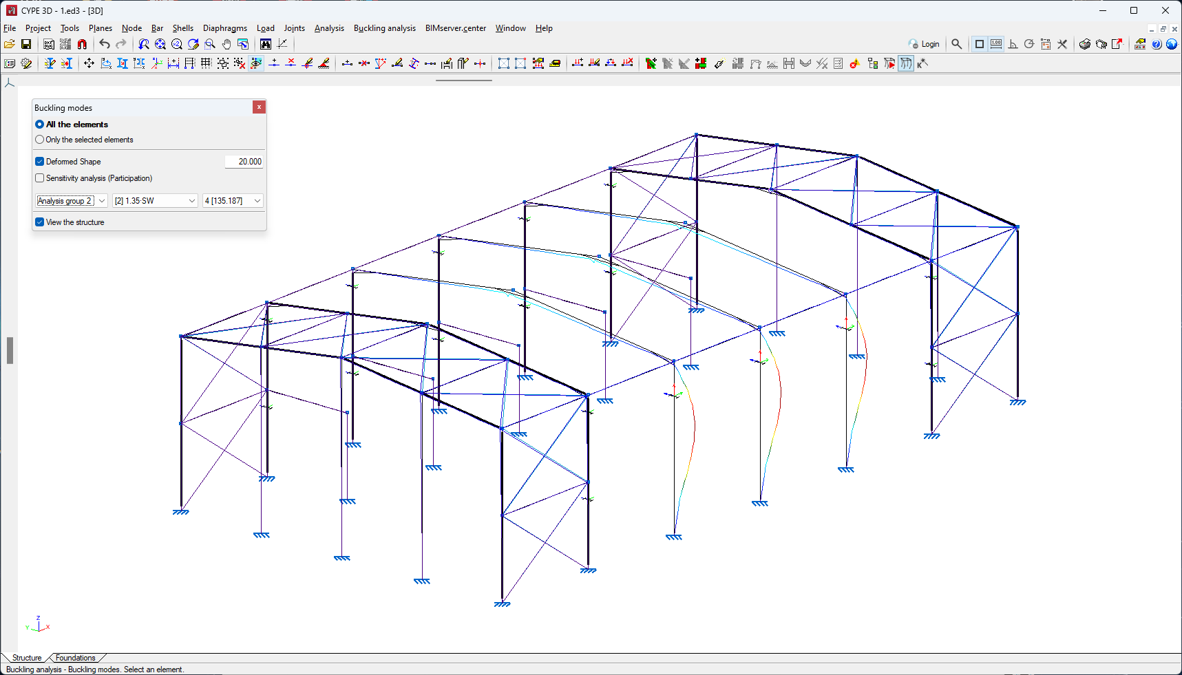
The buckling analysis results are displayed for the selected analysis group.
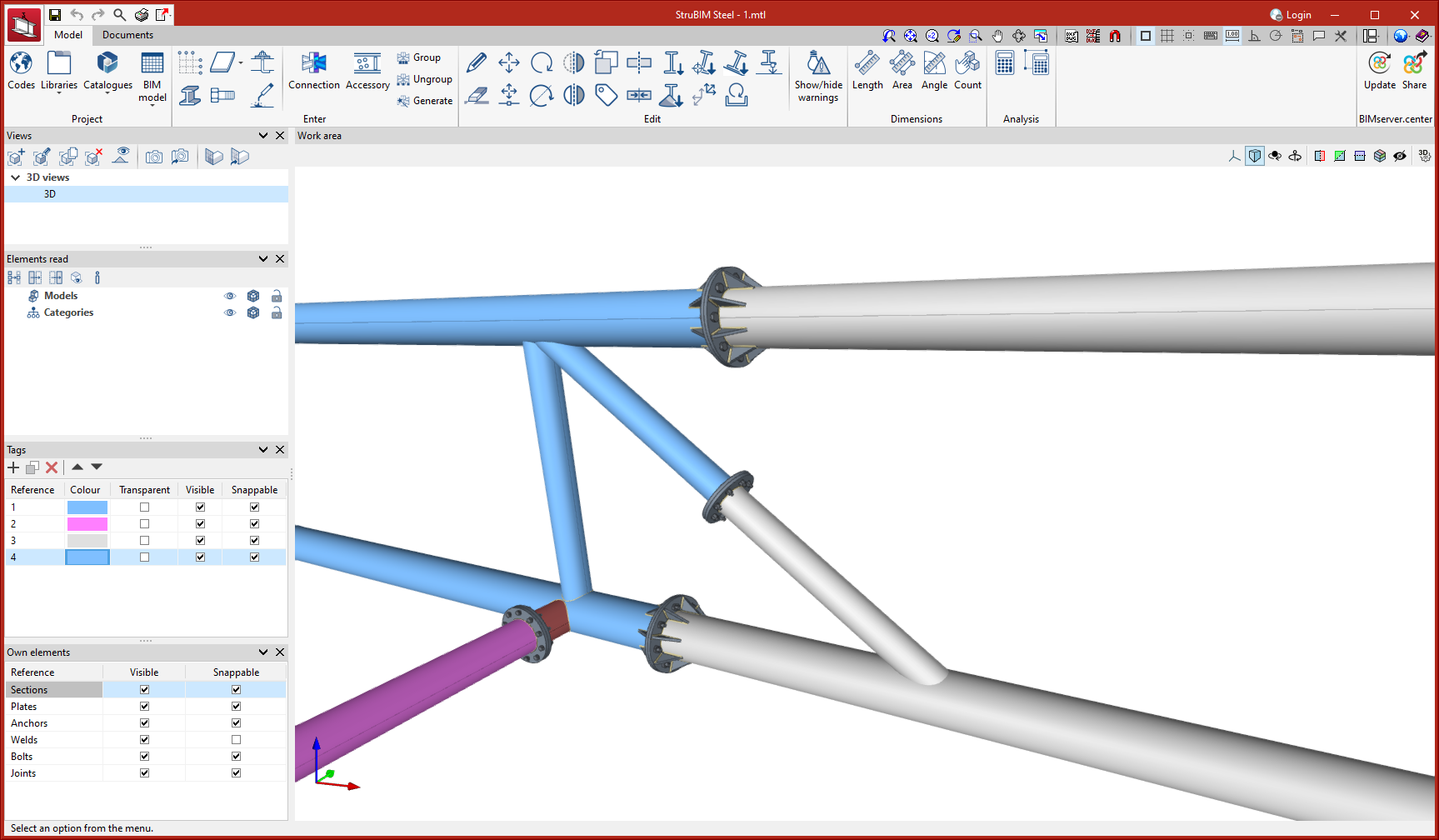
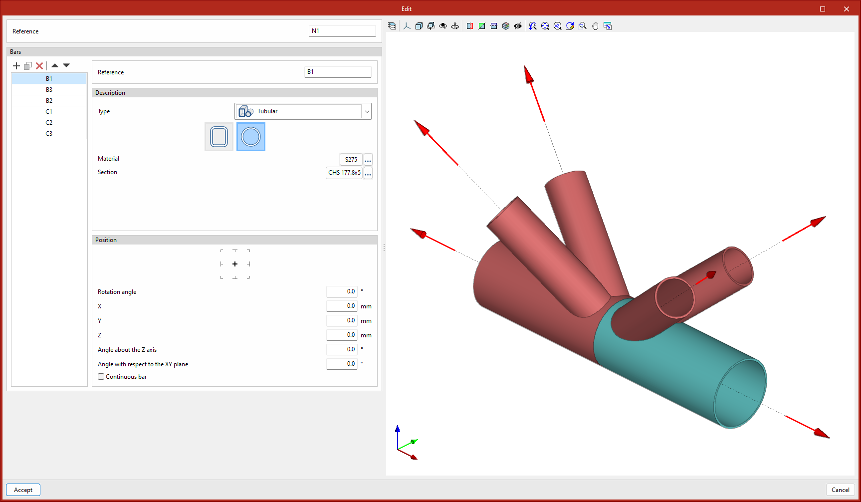
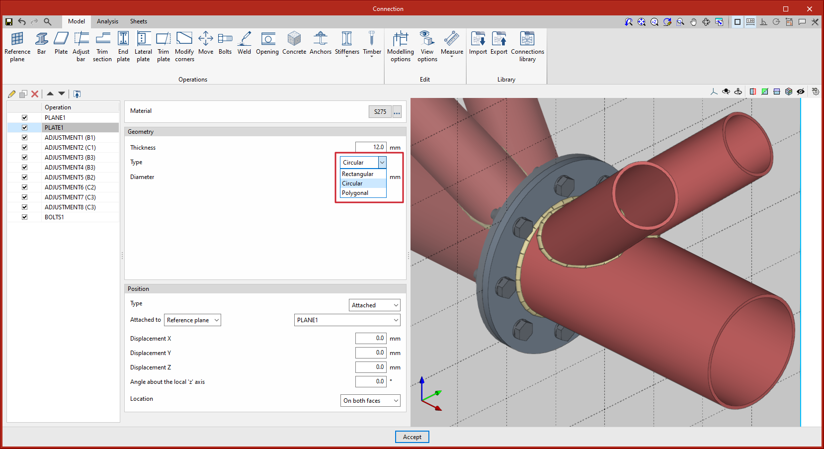
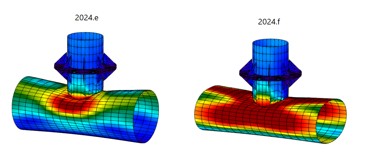
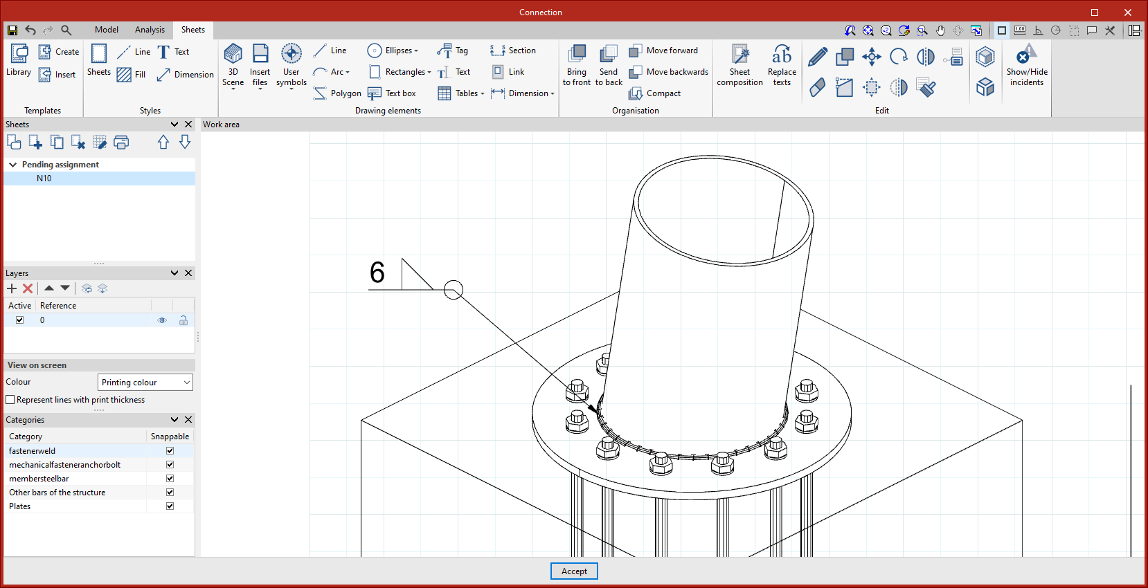
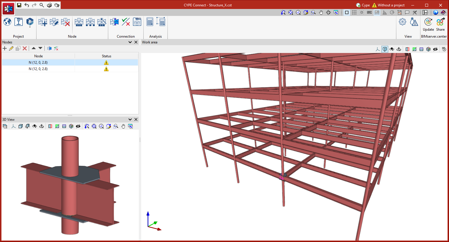
As of version 2024.f, the possibility to model and analyse connections between circular hollow sections in CYPE Connect and StruBIM Steel has been implemented.
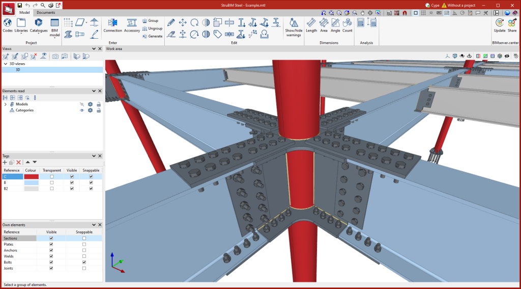
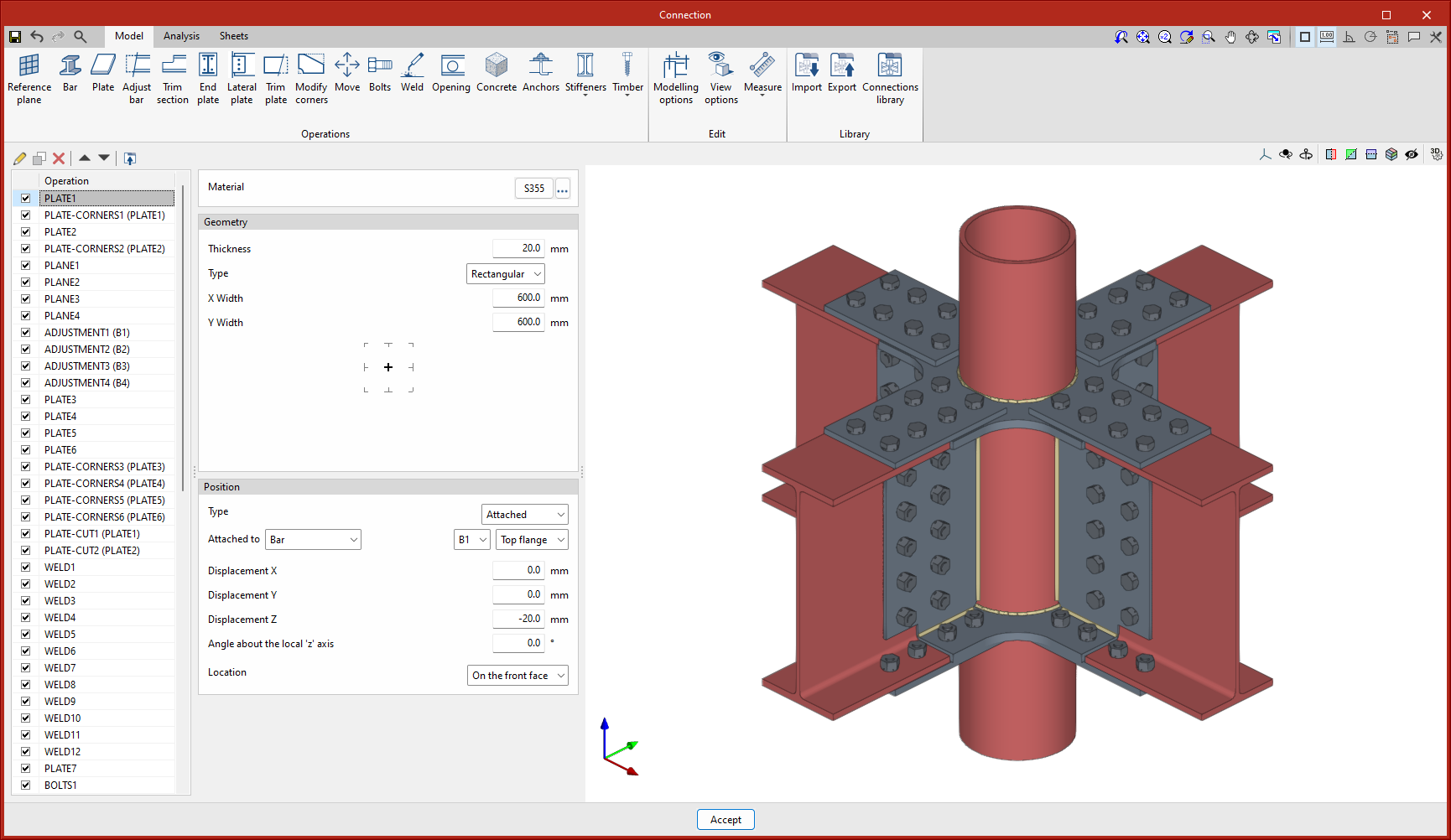
In CYPE Connect, the node editing panel includes the option to select circular hollow sections within the hollow sections option.
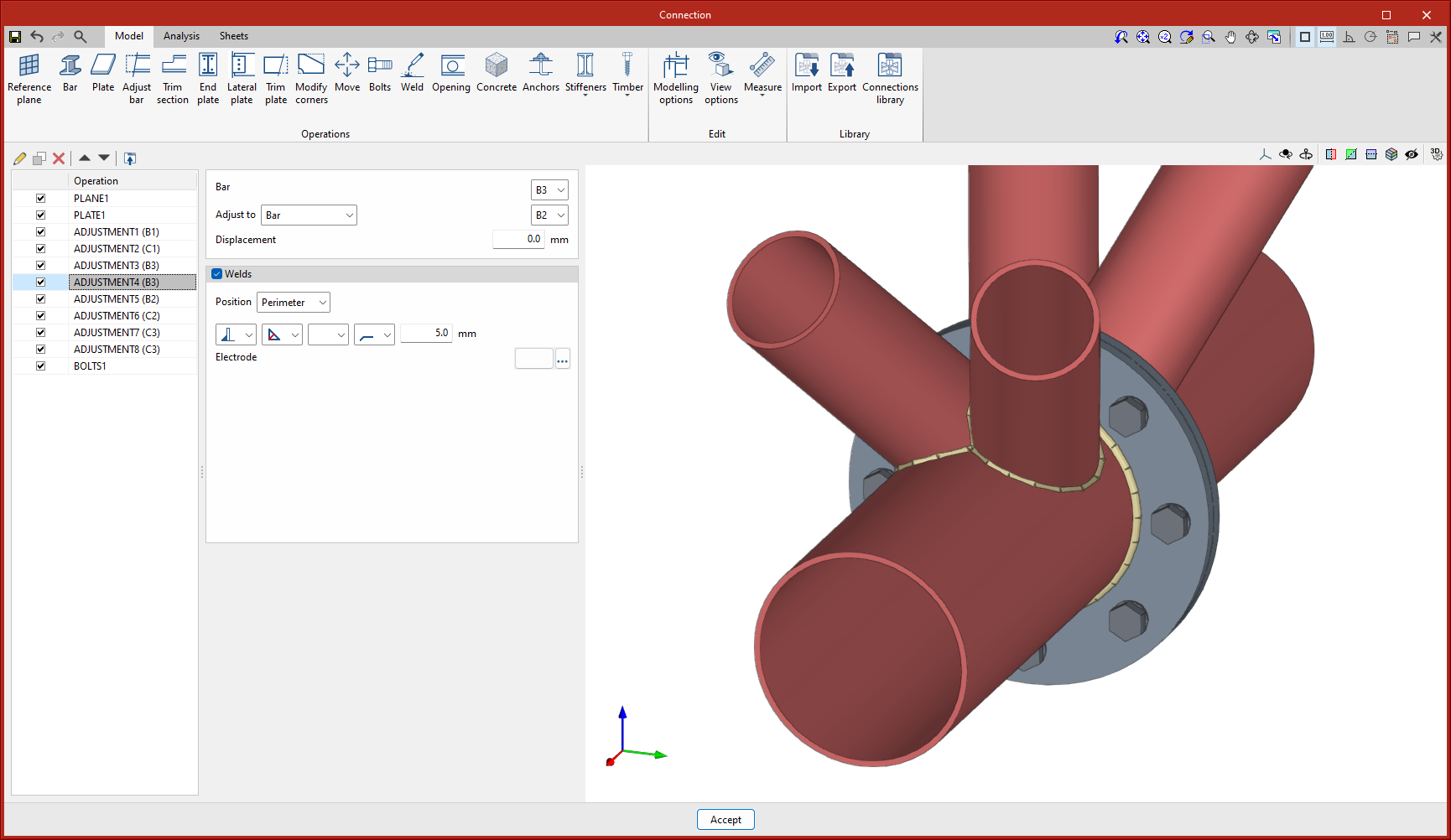
In the connection editing panel, the existing operations adapt their use to work with hollow sections:
- Adjust bar
Allows users to adjust and weld bars to circular hollow sections. Each bar can have more than one adjustment at its ends, whether they are adjustments to planes defined by sections or plates, or adjustments to circular hollow sections.
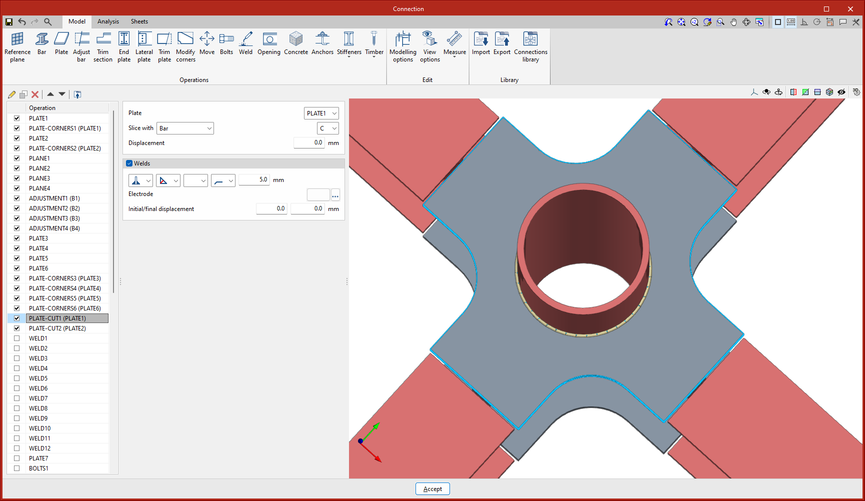
- Trim plate
Allows a plate to be cut out of a hollow section and welds to be added between the plate and the hollow section. The hollow section can create an inner opening in the plate, or an outer trim, thus modifying the perimeter of the plate.
- Weld
Welds between circular hollow sections, or between circular hollow sections and plates have to be defined in the "Adjust bar" and "Trim plate" operations if the hollow section cuts the plate. From the "Weld" operation, users can add welds between plates and circular hollow sections in cases where any edge of the plate is parallel to the longitudinal axis of the hollow section.
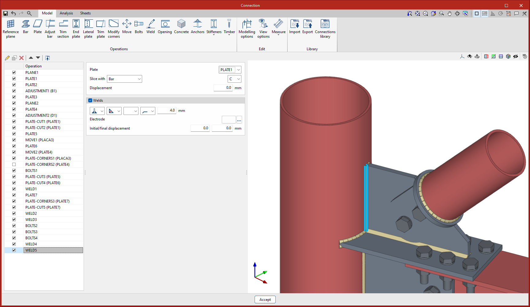
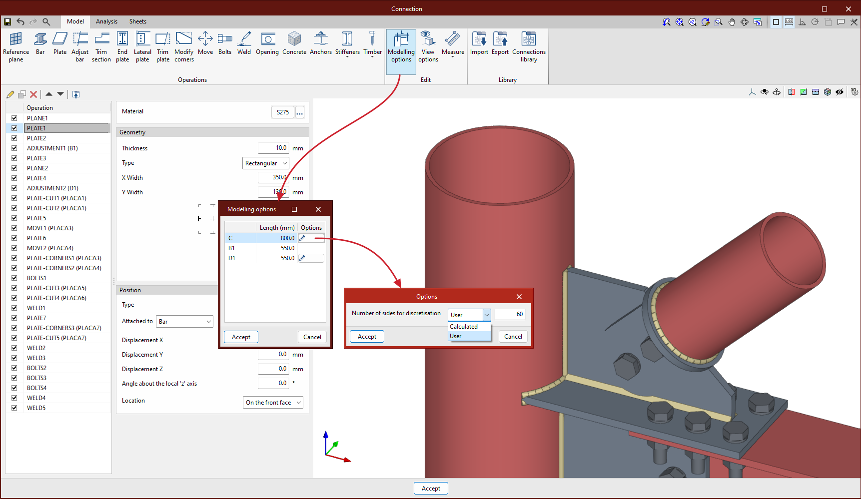
The setting of the number of sides for the discretisation of the circular hollow sections can be found under "Modelling options". A user value or a value calculated automatically by the program can be defined.
Tubular hollow sections with a circular section are discretised by means of quadrilaterals and the number of elements can be reduced, thus reducing the analysis time.
Up until version 2024.f, a circular plate could be defined by using the "Polygonal" option to create 2 or more curved sections.
As of version 2024.f, the "Plate" operation includes the new "Circular" option.
This new option allows users to define a circular plate more easily.
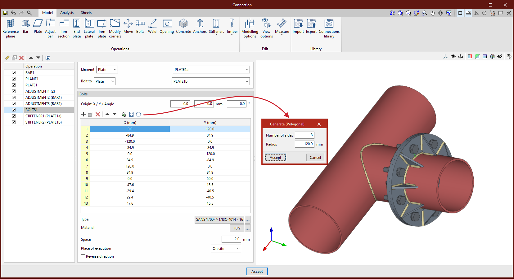
As of version 2024.f, the bolt and screw position table includes a new option to generate bolts radially by defining the number of bolts and the radius.
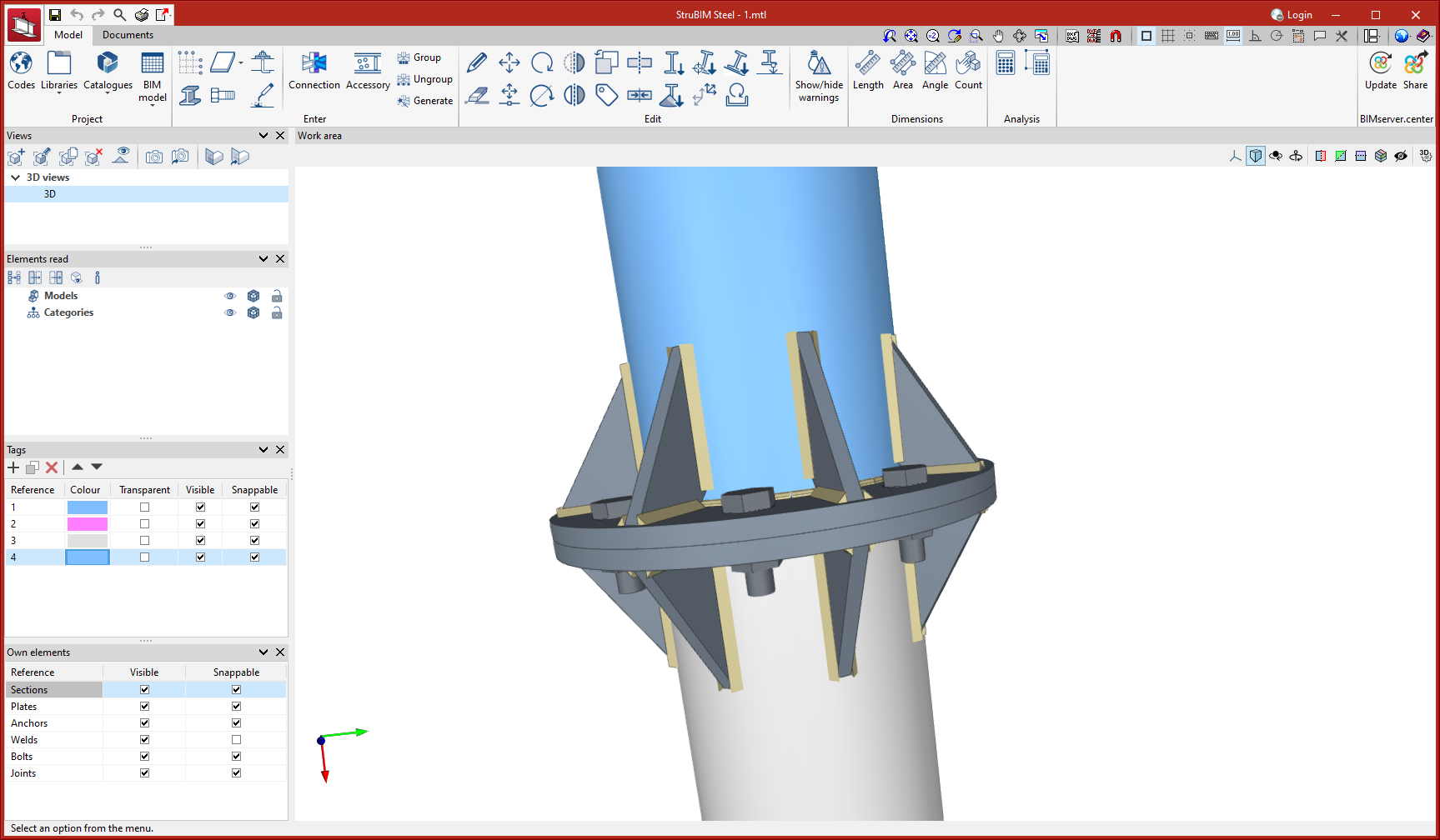
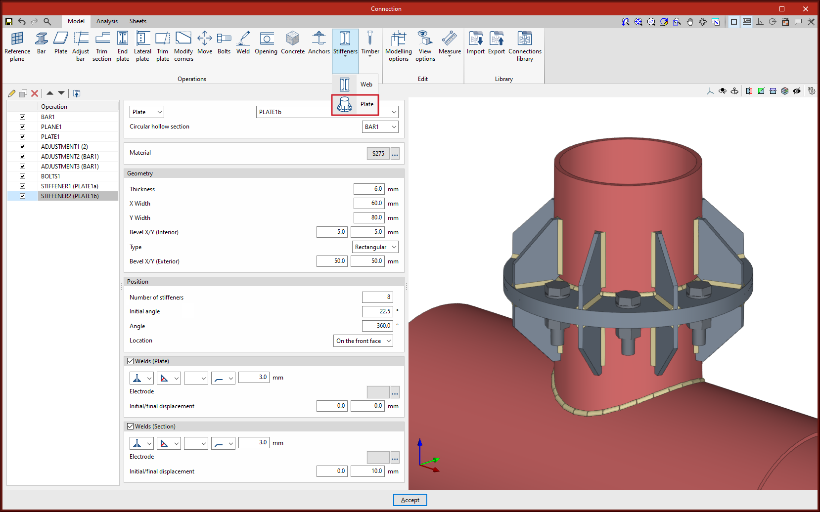
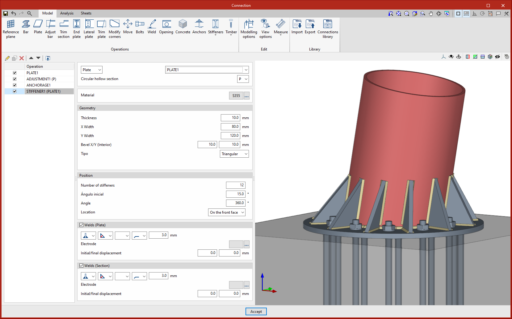
In version 2024.f a new operation is implemented to add stiffeners between a plate and a circular hollow section. The stiffeners are arranged around the circular hollow section radially and parallel to the section axis.
As well as the geometry of the stiffeners, users can define the number of these plates, which will be evenly distributed from an initial angle, around the user-defined angle. The point of origin of the initial angle coincides with the y-axis of the section.
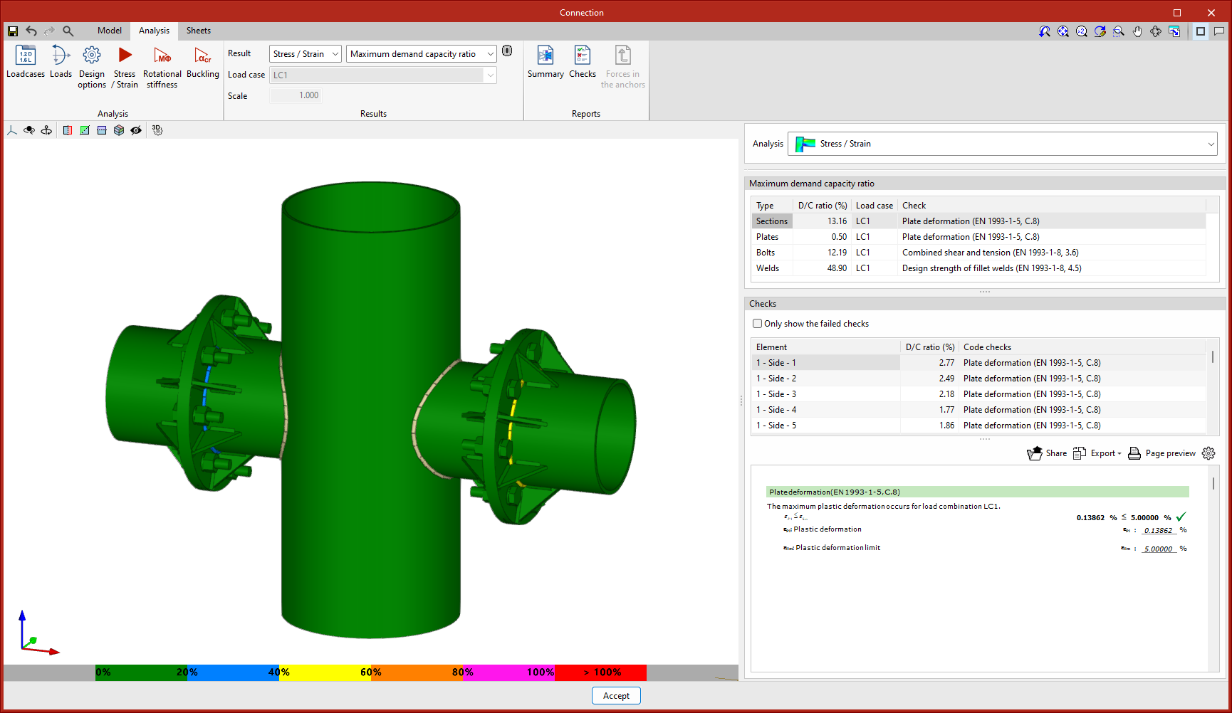
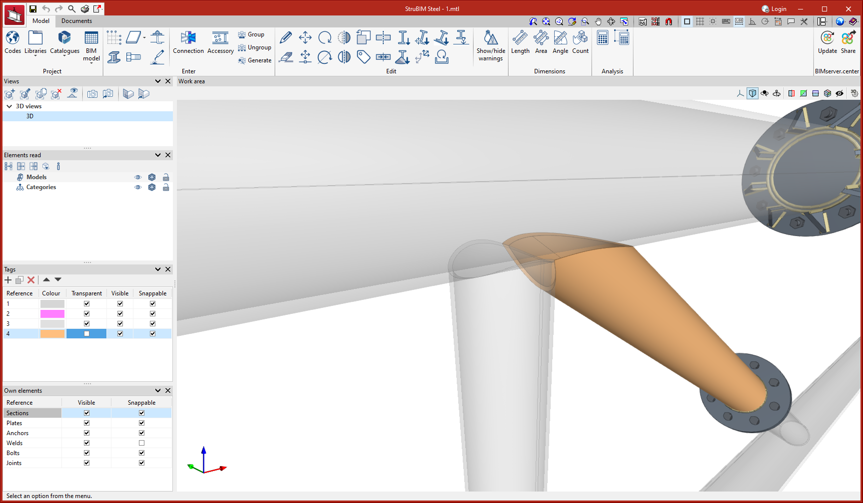
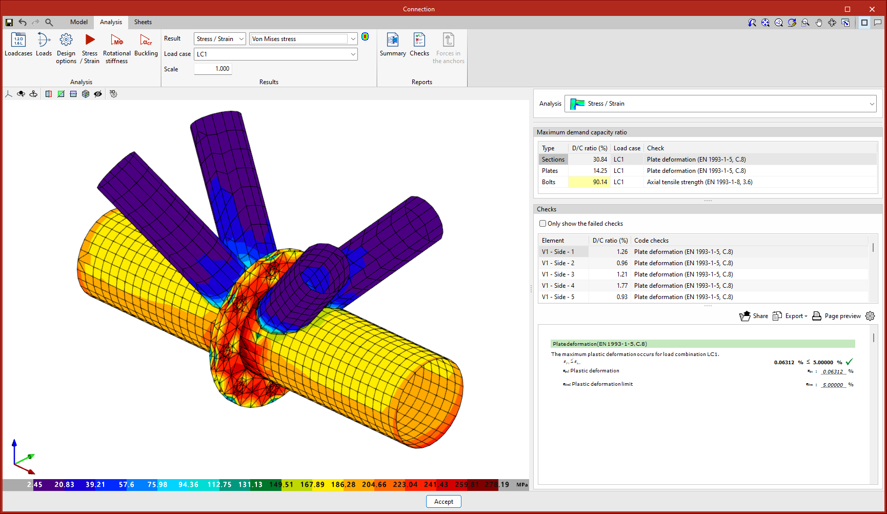
In version 2024.f, changes have been implemented in the finite element model of the connections compared to previous versions.
For the stress/strain analysis, the new model incorporates an additional extension of the bars, which consists of a linear elastic plate system and a reduced number of elements.
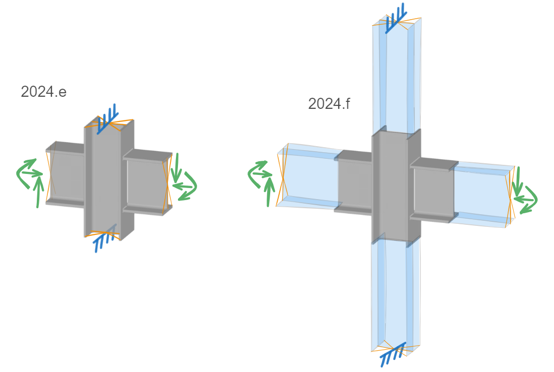
The extension allows users to consider the effect of modelling bars with a longer length, without penalising the analysis time.
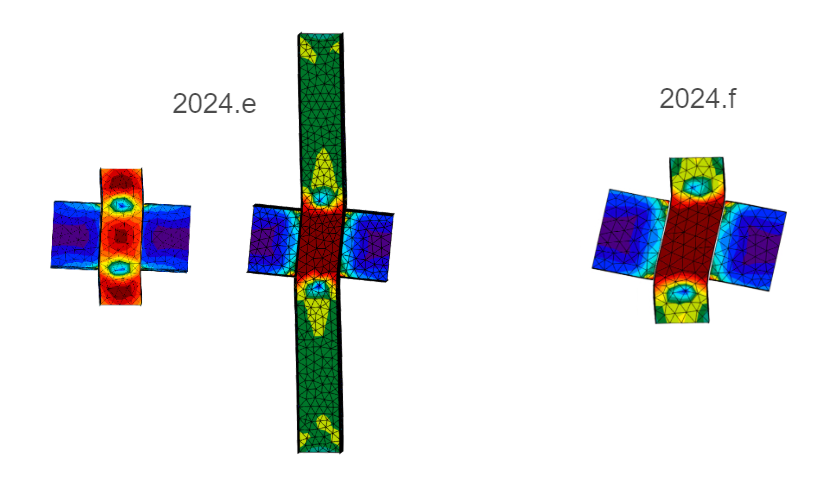
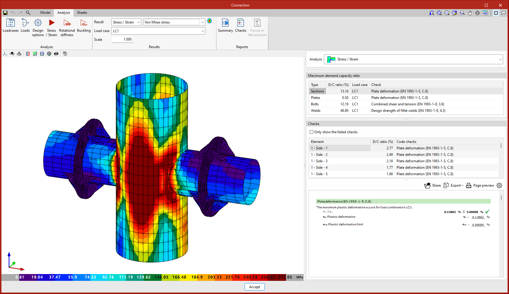
The end nodes of each bar are bound with rigid links to apply loads or restrictions, which implied that the end section of each bar was considered to be non-deformable. In some cases, this assumption could lead to stress concentrations at the ends, or to less conservative results.
With the new model, the non-deformable section is moved away from the connection to the end of the additional extension to avoid these issues.
This additional extension is neither represented in the connection modelling tab nor in the results tab.
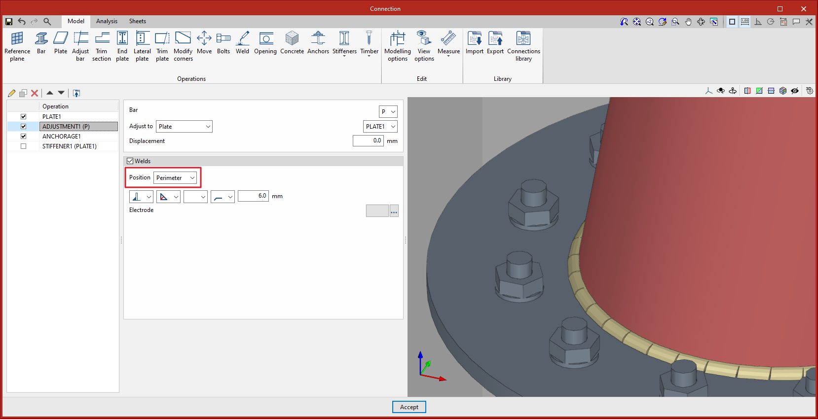
The "Adjust bar" and "End plate" operations include a new option when defining welds: the choice between perimeter welding or parametric welding. Up until version 2024.f, welds were always placed parametrically on wings and webs, depending on the type of section.
The new perimeter welding option will add welds along the entire contact area between the selected elements. For circular hollow sections, the weld must always be a perimeter type.
Perimeter welds shall be shown on the drawings with their corresponding symbols.
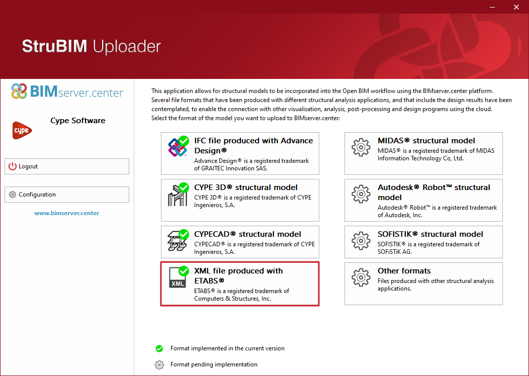
As of version 2024.f, ETABS® structures can be imported into CYPE Connect and StruBIM Steel.
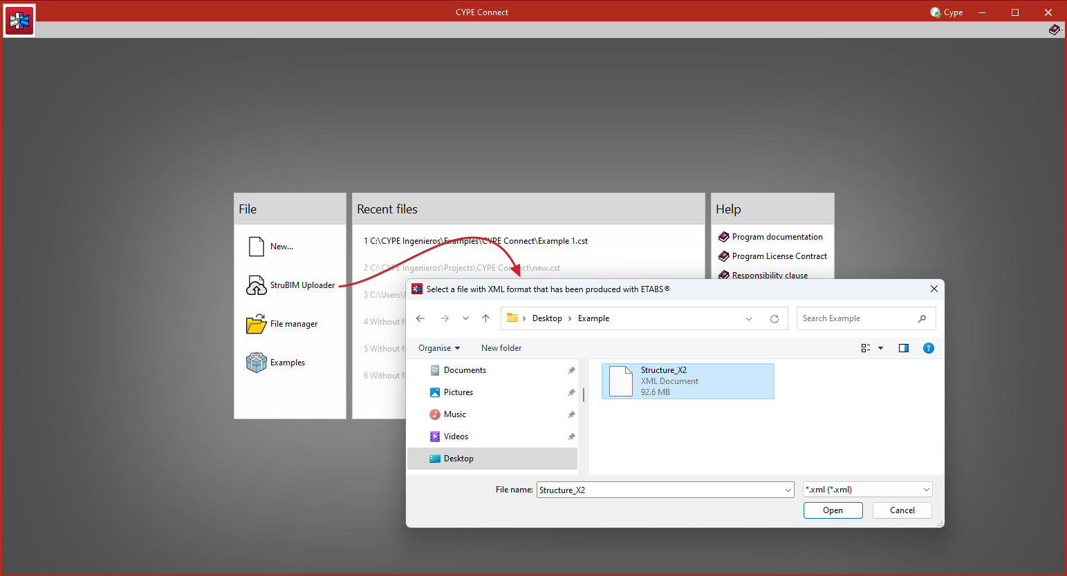
An XML file containing all the model definition tables (MODEL DEFINITION) and the bar force tables (ANALYSIS RESULTS > Element Output > Frame Output) must be exported from ETABS®.
The structure can be imported via StruBIM Uploader or directly into CYPE Connect and StruBIM Steel.
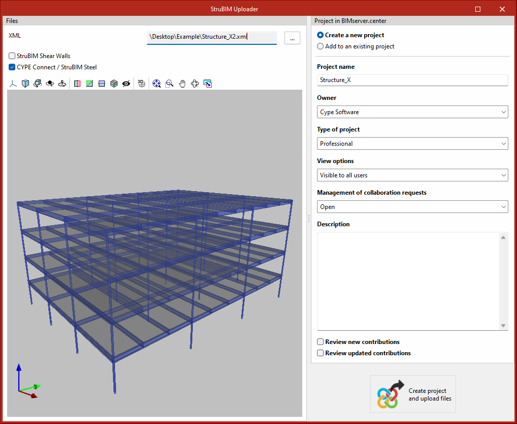
In StruBIM Uploader, by selecting the "XML file produced with ETABS®" option, users access the file selection panel and select the BIMserver.center project, to which the data will be uploaded.
Information can be generated for StruBIM Shear Walls and for CYPE Connect or StruBIM Steel.
After exporting to BIMserver.center, in CYPE Connect or StruBIM Steel simply create the job from that BIMserver.center project.
In CYPE Connect and StruBIM Steel, it can be imported directly via direct access to the StruBIM Uploader.
The bars and the forces in the bars are imported.
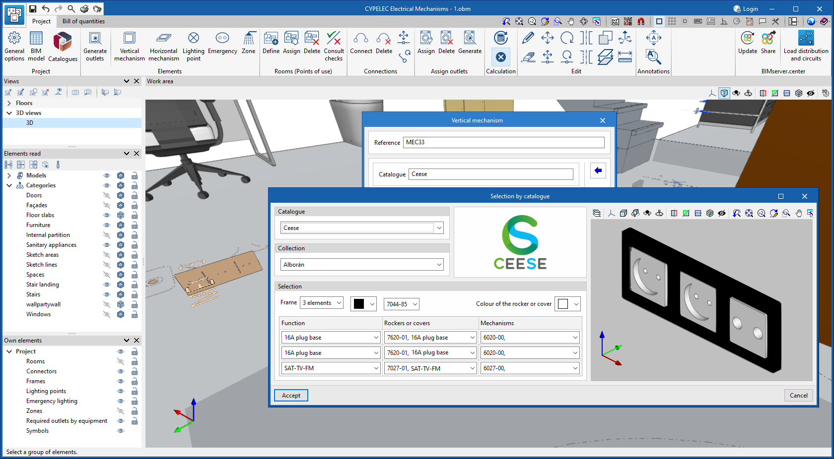
In CYPELEC Electrical Mechanisms version 2024.f, users now have the option of selecting one or more wiring device manufacturer’s catalogues.
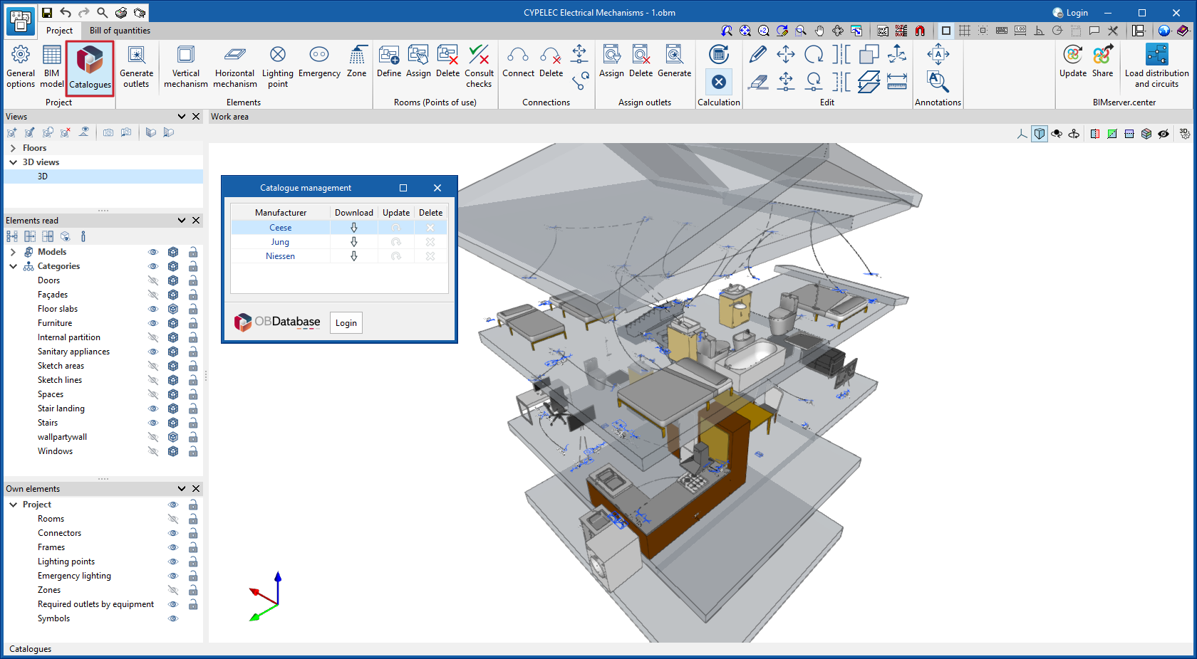
By selecting a catalogue, users can configure wiring devices with solutions provided by the manufacturer and their possible colour combinations.
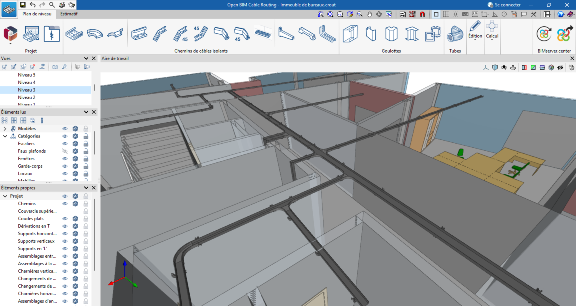
As of version 2024.f, Open BIM Cable Routing can also be installed in French. The application can now be installed in the following languages:
- Catalan
- English
- French
- Portuguese
- Spanish
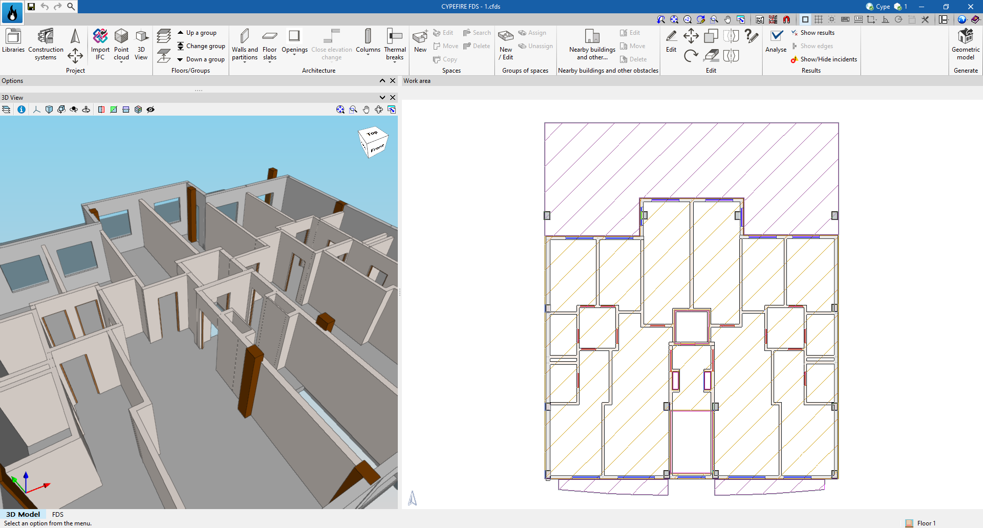
The "3D Model" tab has been added at the bottom left, giving the application the "3D Model" and "FDS" tabs.
This new tab, "3D Model", fully integrates IFC Builder into the program, allowing users to create a geometric model either with the simplified definition or by construction system of the different construction elements, as it incorporates the Open BIM Construction Systems database. Furthermore, the geometric model for the "FDS" tab is generated from this tab.
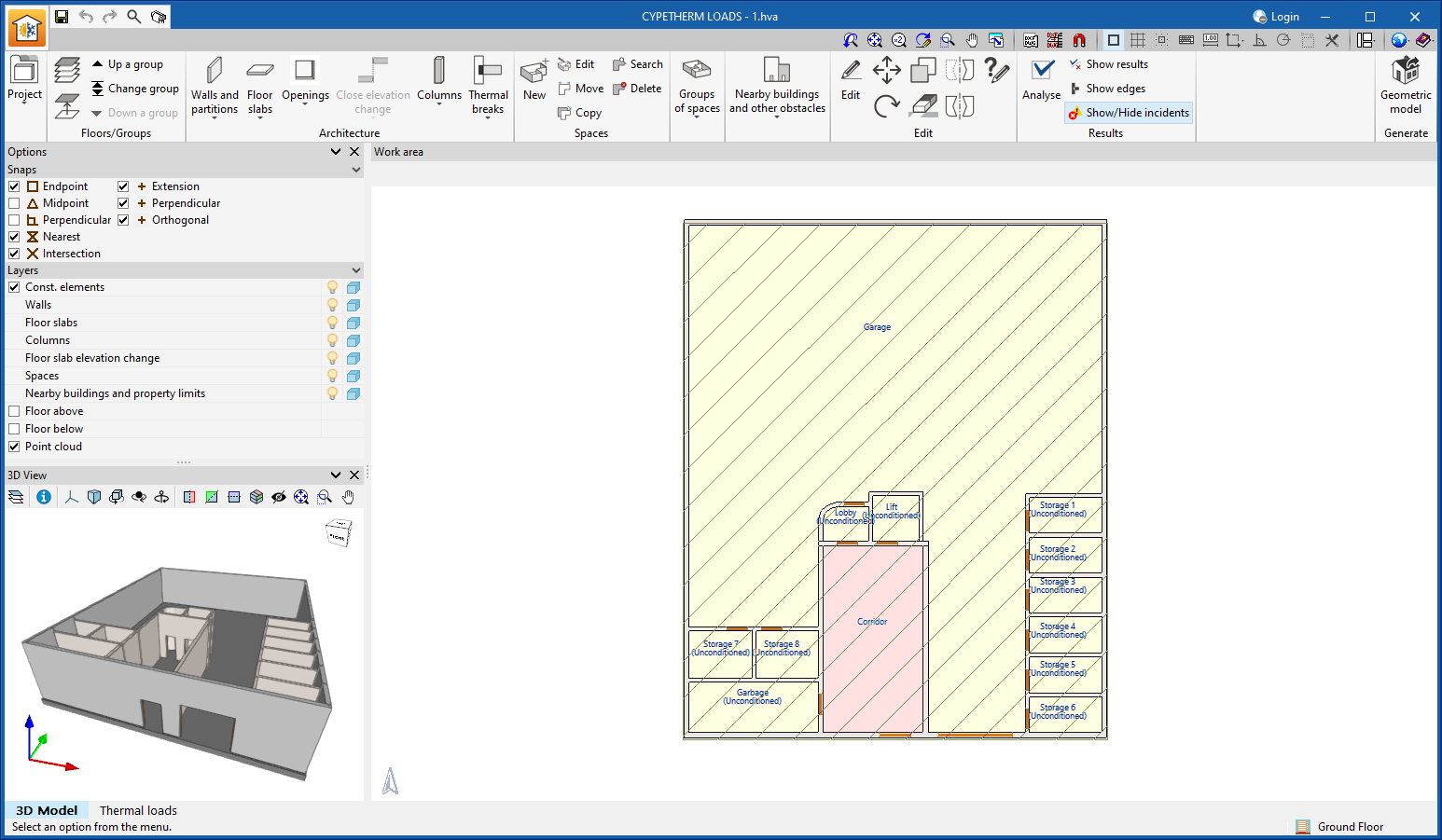
In version 2024.f, the CYPETHERM LOADS application has been remodelled. The "Analytical model" tab has been removed and the "3D model" tab has been added at the bottom left, leaving the application with the "3D model" and "Thermal loads" tabs.
This new tab, "3D Model", makes it possible to fully integrate IFC Builder into the program, allowing users to create a geometric model of the different construction elements with a simplified definition or by construction solution, as it incorporates the Open BIM Construction Systems database. Furthermore, the analytical geometric model for the "Thermal loads" tab is generated from this tab.
Models from IFC Builder and Open BIM Analytical Model can still be read.
The following improvements have been made in addition to the above:
- Export to the BIMserver.center project
Joint export of the "3D model" and "Thermal loads" tabs as a single contribution to the BIMserver.center project, so that the information generated by the geometric model and the results of the thermal loads will be available in the same contribution. - Incorporation of the "Assign type" tool in the "Thermal model" tab
This tool allows users to assign types of an element to other elements in the model view. - Incorporation of two options when updating the geometric model:
- Keep the previously defined types in the thermal model
If this option is selected, the types of the existing building elements in the thermal model will not be updated. - Retain the previously defined zoning in the thermal model
This option allows the zoning of the thermal model to be retained without losing the data and systems associated with buildings, zones or groups.
- Keep the previously defined types in the thermal model
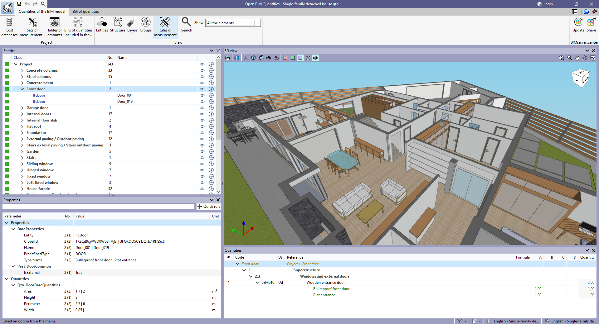
As of version 2024.f, Open BIM Quantities offers five different ways to view the BIM model component tree in the "BIM model measurement" tab.
Until now, elements could be arranged according to the IFC entity they belong to (IfcWall, IfcSlab, IfcSpace, etc.), the spatial structure (IfcSite>IfcBuilding>IfcBuildingStorey, etc.), from the layer or the group they are in. In this update, the "Rules of measurement" option has been added to the "View" group of options in the application's toolbar. When clicking on this option, the elements are organised based on the rules of measurement where they have been selected. Elements used in a rule of measurement are collected in a branch of the tree, which is assigned the name of the rule of measurement.
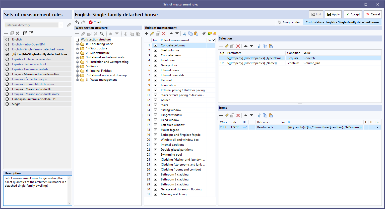
A new "Description" field has been added in the editing window of a "Set of measurement rules", allowing a descriptive text to be associated with the set.
This allows users to provide information on the content or use of the set without the limitations of the "Name" field.
As of version 2024.f, Open BIM Quantities allows users to generate tables of amounts and use the information contained in the model components in these tables.
To configure and display them, the "Tables of amounts" option has been added to the "Project" group of the toolbar corresponding to the "Quantities of the BIM model" tab in the application.
By clicking on it, a window with the tables of amounts defined for the project is displayed.
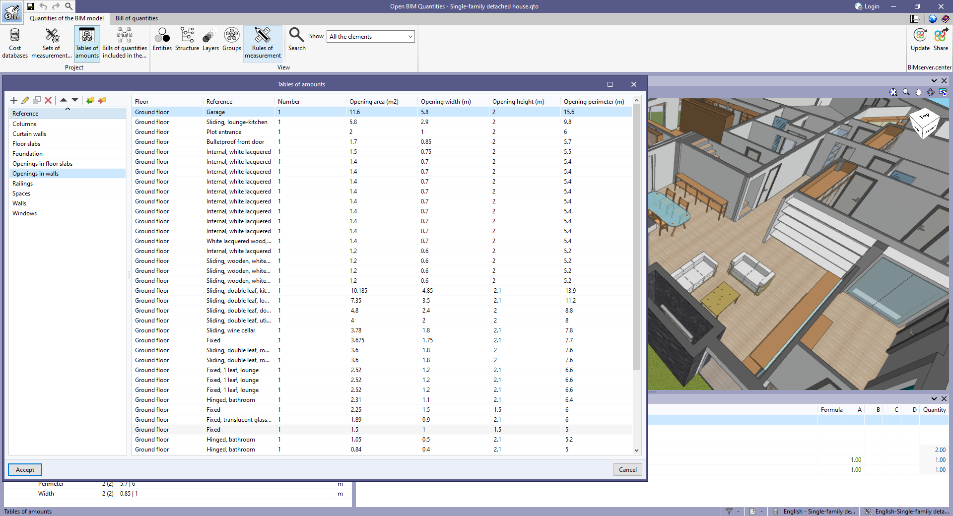
The fields that make up a table of amounts are as follows:
- Reference. Specifies a reference to identify the table in the list of quantity tables.
- Selection. Allows users to establish the conditions that the elements of the project must fulfil to be included in the table.
- Columns. Allows users to define the reference and the content of the columns in the table. To do this, the information contained in the properties and quantities of the project components can be used.
- Sorting criteria. Allows users to indicate the order in which the rows of the table should be inserted based on the information available in the project components.
As the tables are defined based on variables from the model components, they are automatically updated when changes are made to the Open BIM Quantities project. The configuration of the tables of amounts can be exported in a file (".bib804") to be used in other projects.
The tables of amounts can be exported in CSV format so that it can be easily read in a spreadsheet program. Furthermore, a document can be generated with the table, which the application can export in multiple formats (PDF, DOCX, TXT, HTML, etc.).
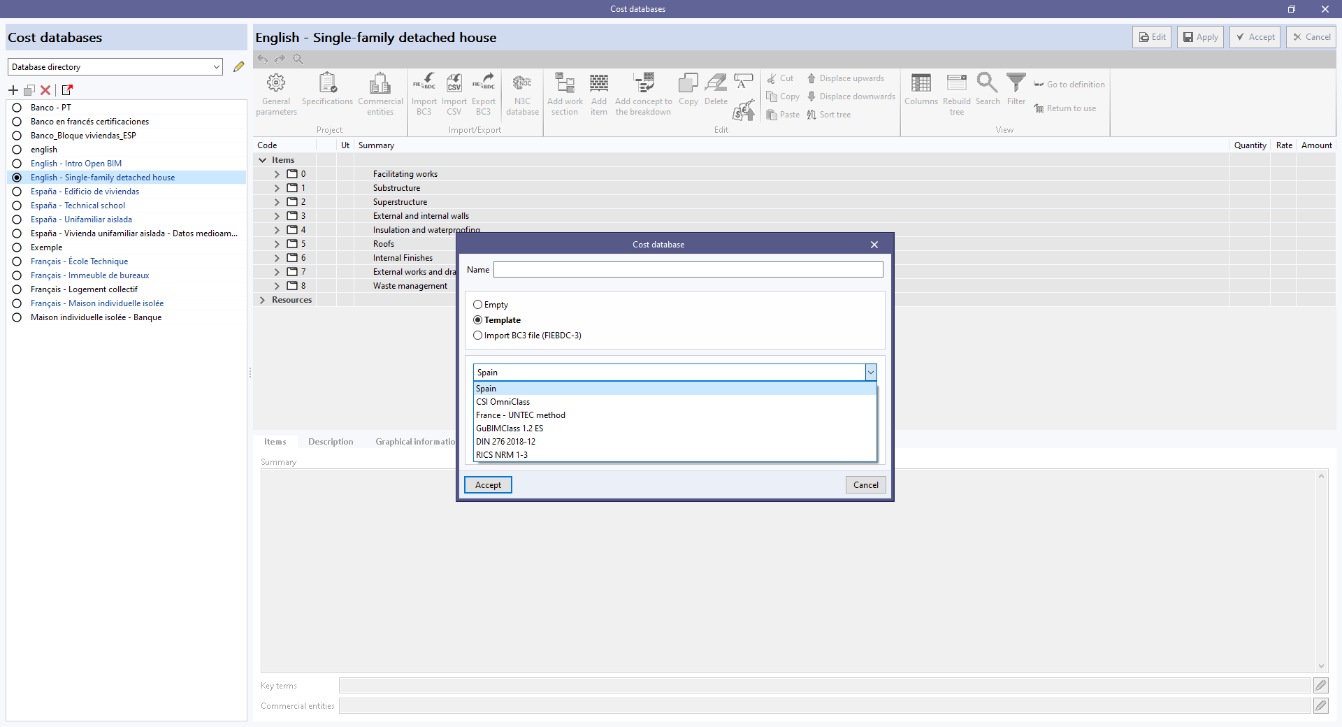
As of version 2024.f, the window for creating a "Cost database" includes the "Template" option.
When selected, users can create a cost database with an initial work section structure.
The following configurations are currently available:
- Spain
- CSI OmniClass
- France – UNTEC method
- GuBIMClass 1.2 ES
- DIN 276 2018-12
- RICS NRM 1-3
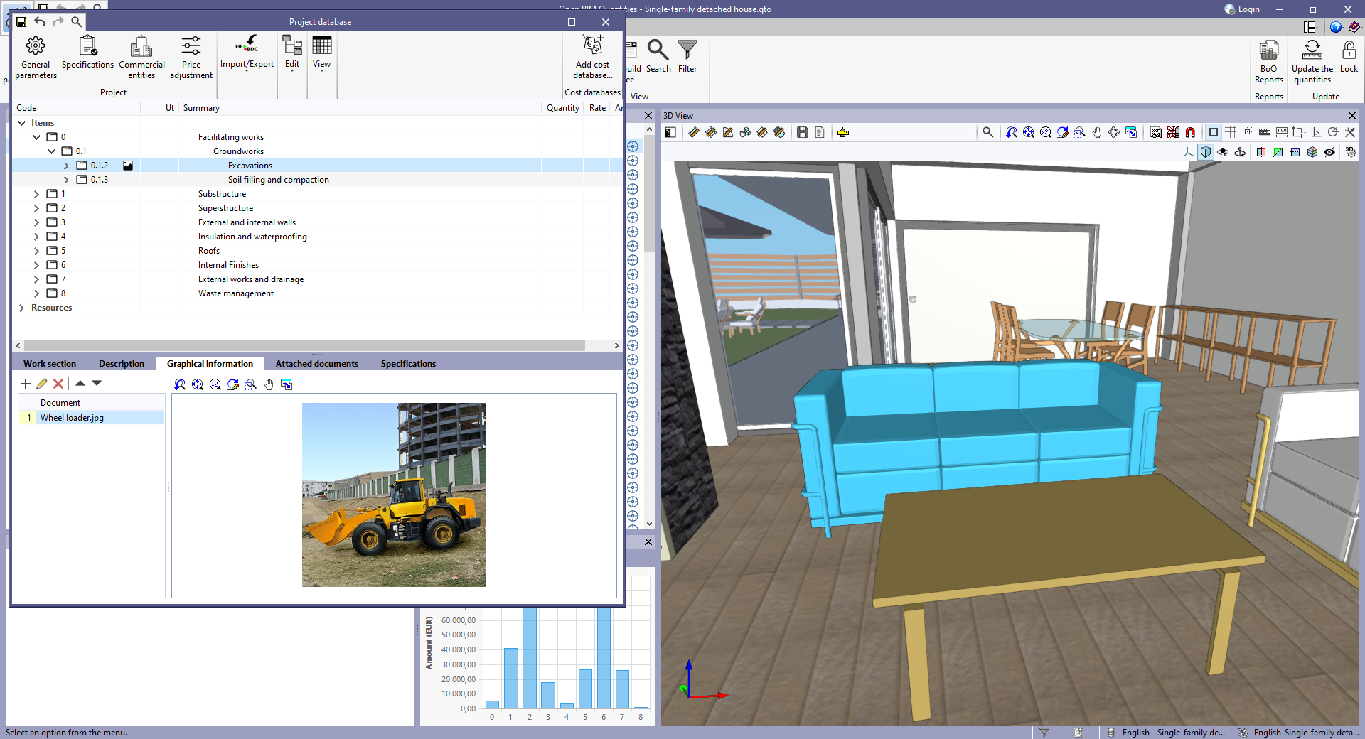
As of version 2024.f, the work sections of a bill of quantities or a cost database can have more information associated with them. For this purpose, the following tabs have been added to the editing panel of a work section displayed within the management menu of the "Project cost database" or of a "Cost database":
- Description
- Graphical information
- Attached documents
In previous versions, this data could only be associated with "Items".
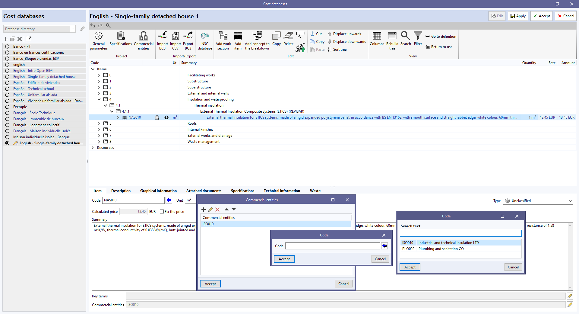
As of version 2024.f, the "Bill of quantities" tab allows commercial information to be entered in the "Project cost database" or a "Cost database".
For this purpose, the "Commercial entities" button has been added to the toolbar in the management window of both elements.
By clicking on it, a menu is displayed where it is possible to define the data of the commercial entities involved in the project or the cost database.
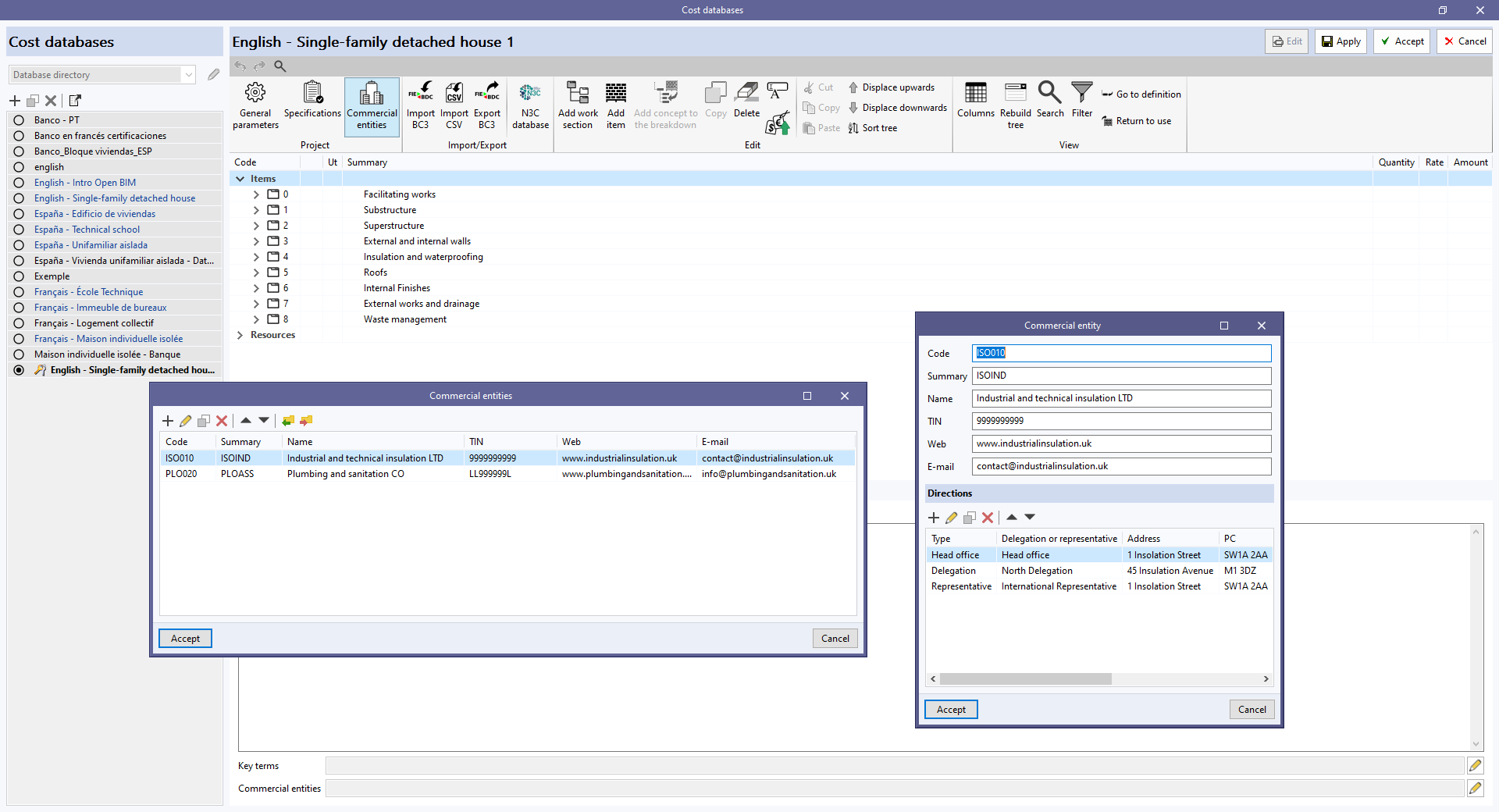
Furthermore, to allow commercial entities to be associated with concepts, the "Commercial entities" field has been added to the editing panel for work sections and items.
Commercial entities are part of the standard database interchange format for the FIEBDC-3 construction database (.bc3). Therefore, this information can be imported and exported using the tools in the "Bill of quantities" tab for managing BC3 files.
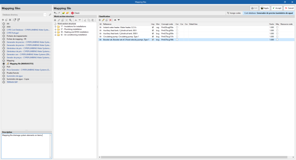
A new "Description" field has been added in the editing window of a "Mapping file" allowing a descriptive text to be associated with the set.
This allows users to provide information on the content or use of the set without the limitations of the "Name" field.
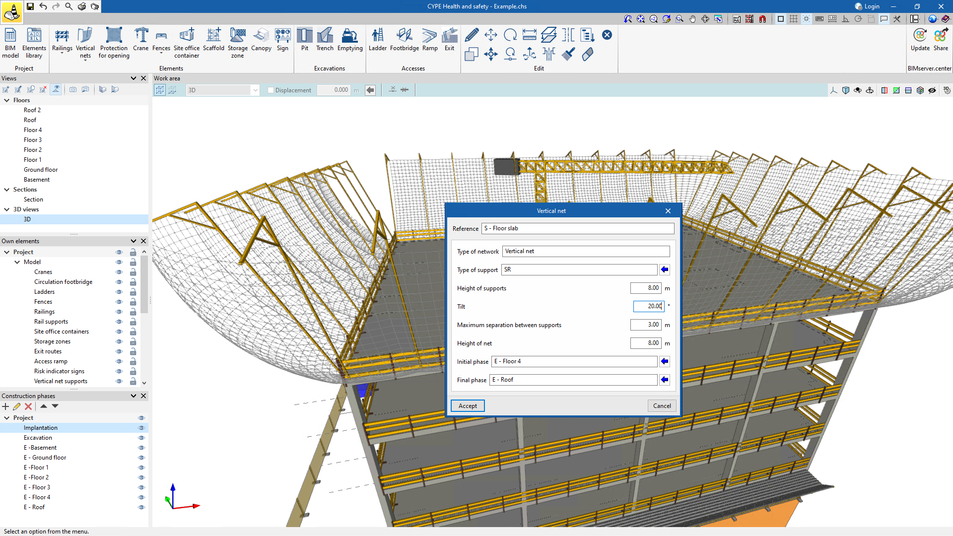
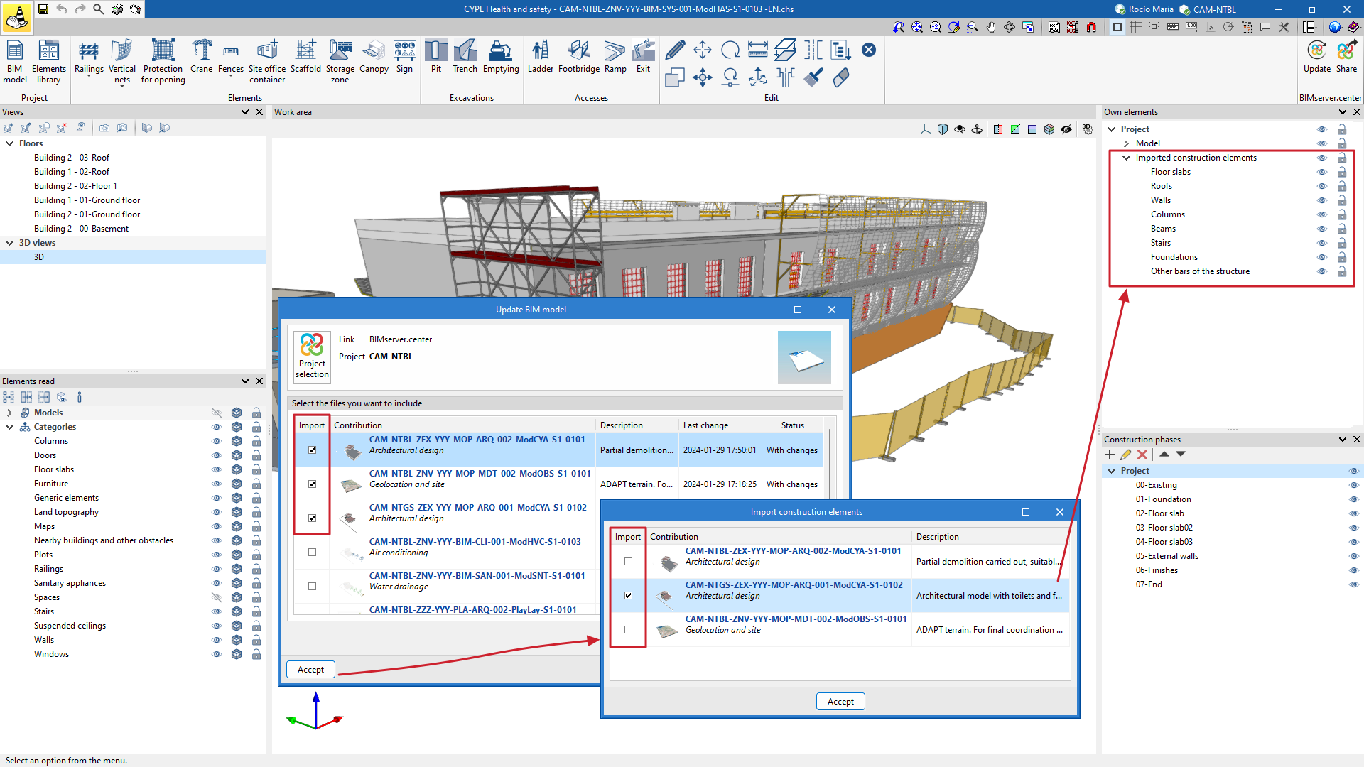
As of version 2024.f, users can select the contributions from which they wish to import the building elements, as well as import the contributions present in the shared project. These imported elements will become part of the CYPE Health and safety work file and can be used as their own references, associated with construction phases.
In previous versions, CYPE Health and safety imported the building elements of all BIM project contributions that users had selected with the "Update" option (Import of BIM models).
This allows users to decide, for example, whether the elements to be imported into CYPE Health and safety are those from the architectural model or the structural model (even if both are visible in the work environment).
Vertical net supports can now be tilted, providing greater flexibility in the design of these systems and allowing them to be adapted to different contexts and architectural needs.