Located in the toolbar of Flow diagram tab is the Toshiba VRF systems block, which contains the elements required to introduce a variable refrigerant flow system of this manufacturer.
Interior units
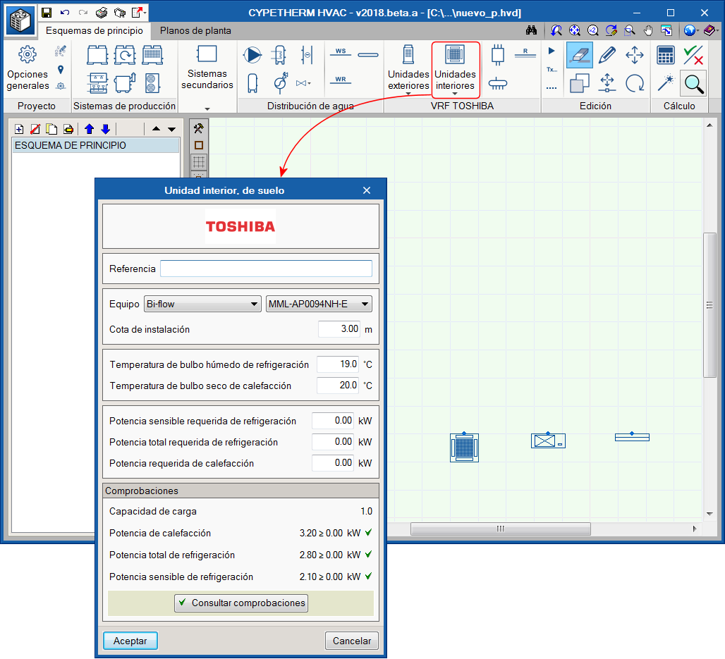
Interior units must be located in the same space to be conditioned, and can be cassette, duct, wall, floor or ceiling-type units.
For each type of unit, there is a series of sizes with a nominal heating and cooling power. This nominal power will be corrected by the program depending on the indoor design conditions, pipe lengths and, finally, the capacity of the selected outdoor unit. The panel contains the thermal loads and the design conditions of the space to be conditioned. The program checks that the selected unit is capable of taking on those loads.
Exterior units
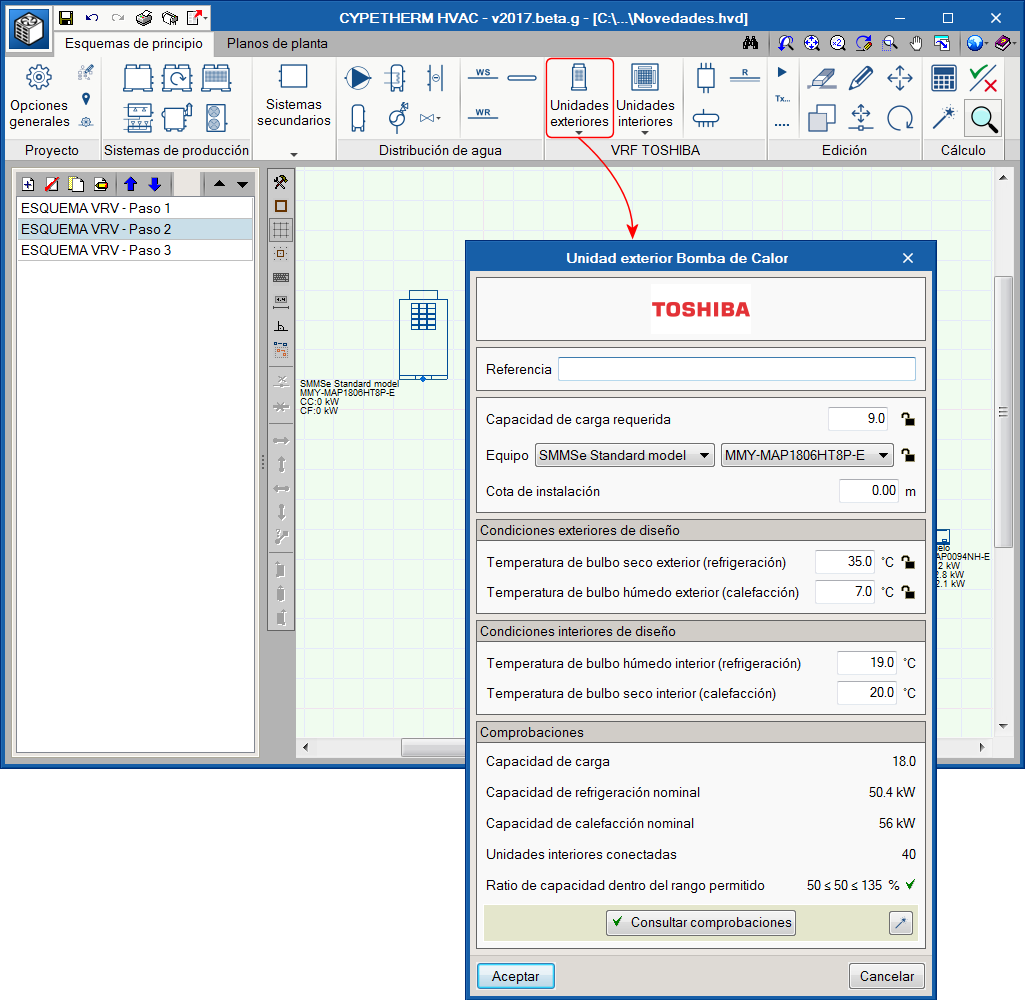
All the indoor unit network is connected with pipes to an outdoor machine, which can be a heat pump (2 pipes), or with heat recovery (3 pipes). That which is selected will determine the type of system.
- Exterior unit, heat pump
In this 2-pipe system, the outdoor unit will provide cold to all the indoor units at the same time, or heat to all the indoor units. - Exterior unit with heat recovery
In this type of 3-pipe system, the machine will provide cold to some indoor units and heat to other indoor units simultaneously. For this to be possible, a flow selector unit must be placed upstream of each indoor unit.
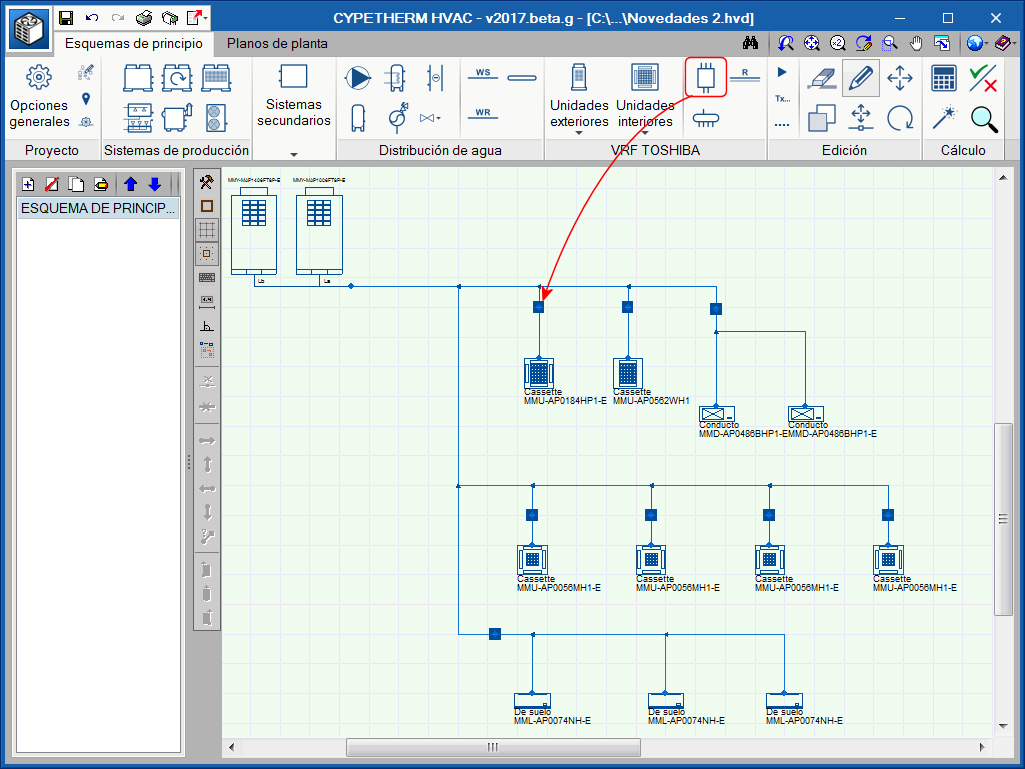
Refrigerant pipes
The pipes are drawn schematically and the program selects their diameters depending on the sum of the capacity coefficients (i.e. the thermal capacity they transport) of the units located downstream and the location of the pipe in the system.
Flow selector units
Flow selector units, also known as boxes, are devices placed in 3-pipe systems, i.e. when the exterior unit is a “with heat recovery” type unit. This device has 2 pipes on one side (which connects to the interior unit) and 3 pipes on the other. Its function is to feed the interior unit with gas or refrigerant, depending on the thermal needs at the time.
Branch circuits
Each time a main pipe splits to create a branch, it does so with a branch circuit. No icon exists for this element as the program automatically places a branch circuit and selects the required size at each branch.
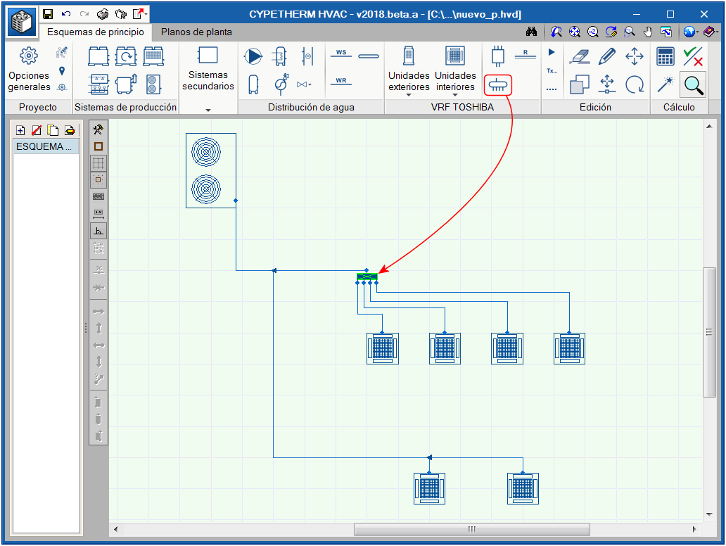
Manifolds
Occasionally, the main pipe has to feed several interior units located at a similar distance. For these cases, it is best to place a manifold with 4 or 8 outlets instead of having several branches that are very close in the main pipe.
Results output
Upon selecting the “Reports” button, the program generates a results report containing all the information regarding the system: element quantities, requirement checks, corrected heating and cooling capacities, circuit diagram.