Open BIM Quantities (new program)
"Open BIM Quantities" is a tool destined to create bills of quantities based on BIM models that have been defined using the IFC standard. This application is integrated into the Open BIM workflow via the BIMserver.center platform.
"Open BIM Quantities" can read the properties and quantities that are contained in the IFC entities that make up the Open BIM model of the building. Users can establish the sets of measurement rules they wish in order to transform the data that is contained in the elements of the model into real items for the bill of quantities. These sets can be saved to be used in other projects.
The items that are then obtained from the BIM model can be linked to concepts of a cost database.
Users can create their own cost databases or import them from databases in FIEBDC-3 format (such as CYPE's cost database Generador de precios).
The program allows users to edit the final result of the quantities and bill of quantities and print reports containing the information that has been generated.
"Open BIM Quantities" also offers users the possibility to export the bill of quantities to FIEBDC-3 format to be used by other cost management programs such as Arquimedes.
Open BIM Analytical Model (new program)
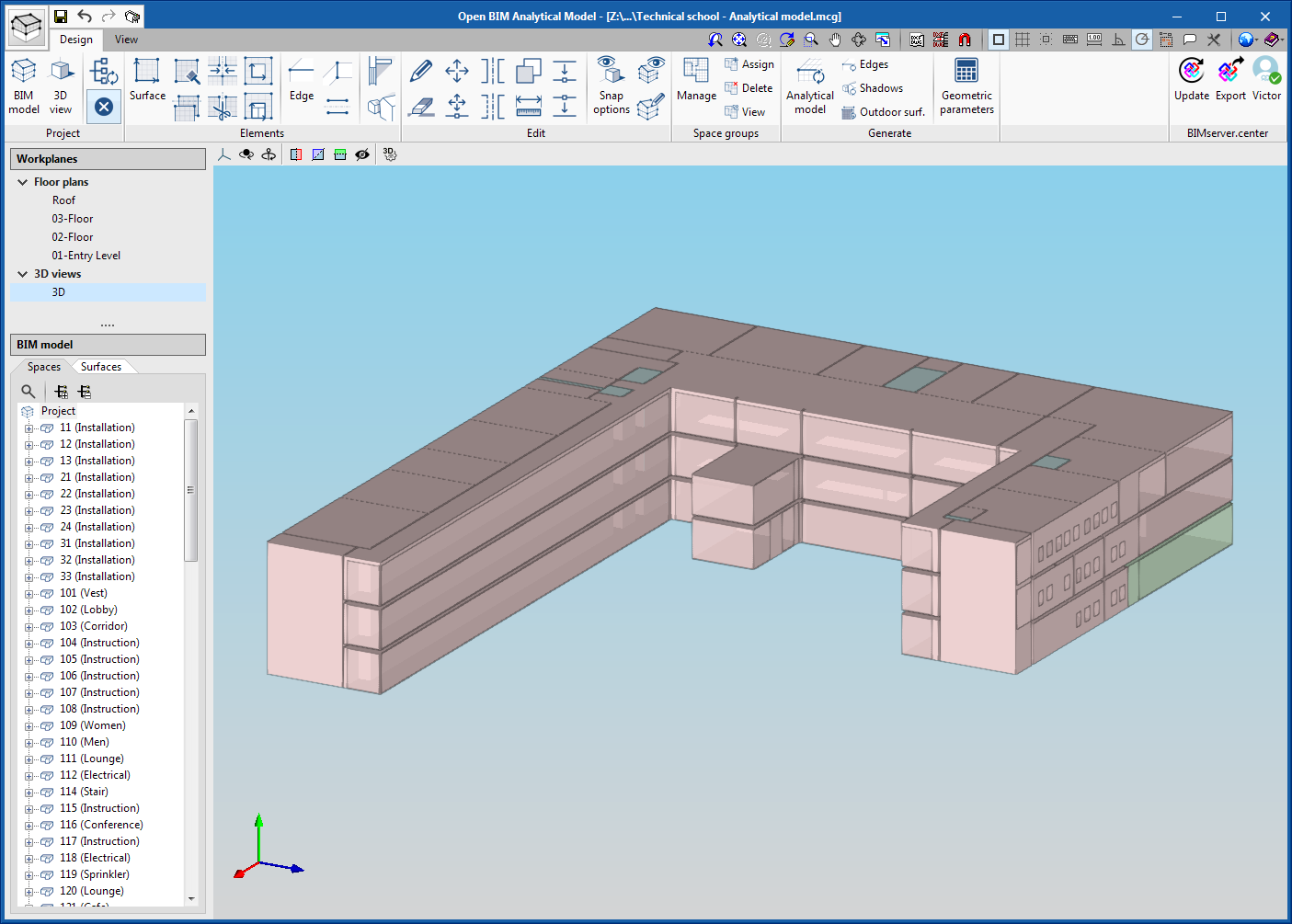
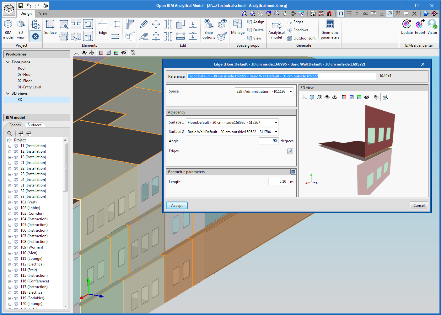
"Open BIM Analytical Model" is an application developed to generate analytical geometric models of buildings in order to carry out their energy and acoustic analysis.
The programme allows users to enter all the elements that make up the analytical model, such as spaces, surfaces, edges, junctions, etc. It is also possible to indicate the existing relationships between these entities (which spaces they belong to, adjacencies between surfaces, edges that form a junction etc).
If there is a BIM project located on the BIMserver.center platform that has an architectural model, "Open BIM Analytical Model" allows specialist users to make use of the automatic generation process and modify the elements they consider necessary to adapt them to their needs.
In order to take into account the different thermal and acoustic requirements, the application allows users to define different space groups for the same analytical model (for example, a group depending on use units and another depending on thermal zone criteria).
The defined analytical model can be exported to the Open BIM project that is located on the BIMserver.center platform, which can then be interpreted and imported by Open BIM applications that are dedicated to the thermal and acoustic analysis of buildings.
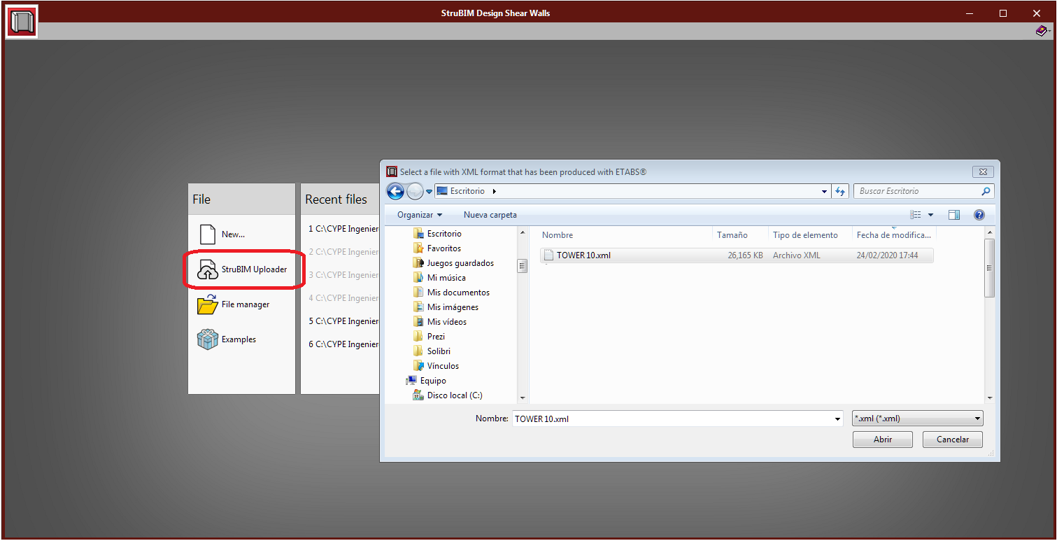
StruBIM Uploader (new program)
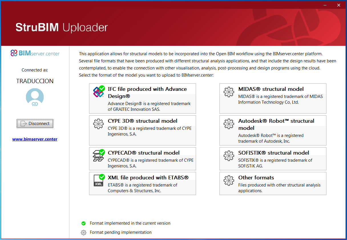
"StruBIM Uploader" is an application that has been developed by CYPE, with which structural models can be incorporated into Open BIM projects that are located on the BIMserver.center platform, and this way enabling a connection with visualization, analysis and post-processing programs of other developers.
In its first version, "StruBIM Uploader" allows users to incorporate models, which have been generated in the following formats by structural design programs, into Open BIM projects, including their design results:
- IFC produced with Advance Design®
- XML produced with ETABS®
"Bill of quantities" tab in project phase Open BIM applications
The "Bill of quantities" tab has been added to the toolbar of some of the applications that are integrated in the Open BIM workflow. In the 2020.e version, the first Open BIM programs to have this tab are:
- Open BIM Quantities (new program of the 2020.e version)
- CYPE Accessibility
- CYPE Lightning
- CYPEPLUMBING Sanitary Systems
- CYPEPLUMBING Water Systems
- CYPEPLUMBING Solar Systems
- CYPEFIRE Hydraulic Systems
- CYPEHVAC
- CYPEHVAC Ductwork
This tab will be integrated into the remaining Open BIM applications in upcoming versions.
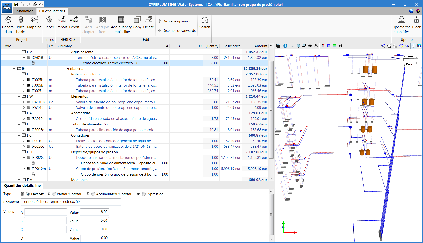
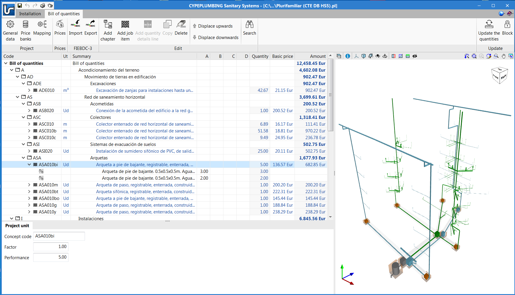
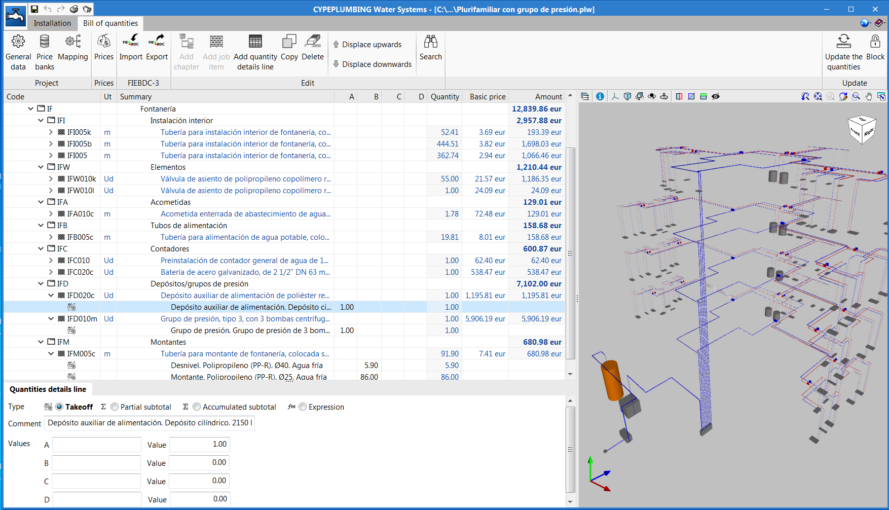
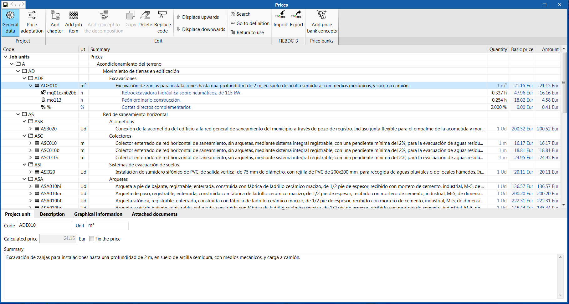
The "Bill of quantities" tab provides users with tools to generate and manage the bill of quantities of the installation that each program analyses. Within this tab, users can extract the quantities of the model and, based on that information, generate the real project items. This process is carried out using a correspondence system between the elements that have been measured in the design model and the concepts of the bill of quantities (mapping). This equivalence is stored on a local drive or network, so that it can be extended progressively and used in future projects.
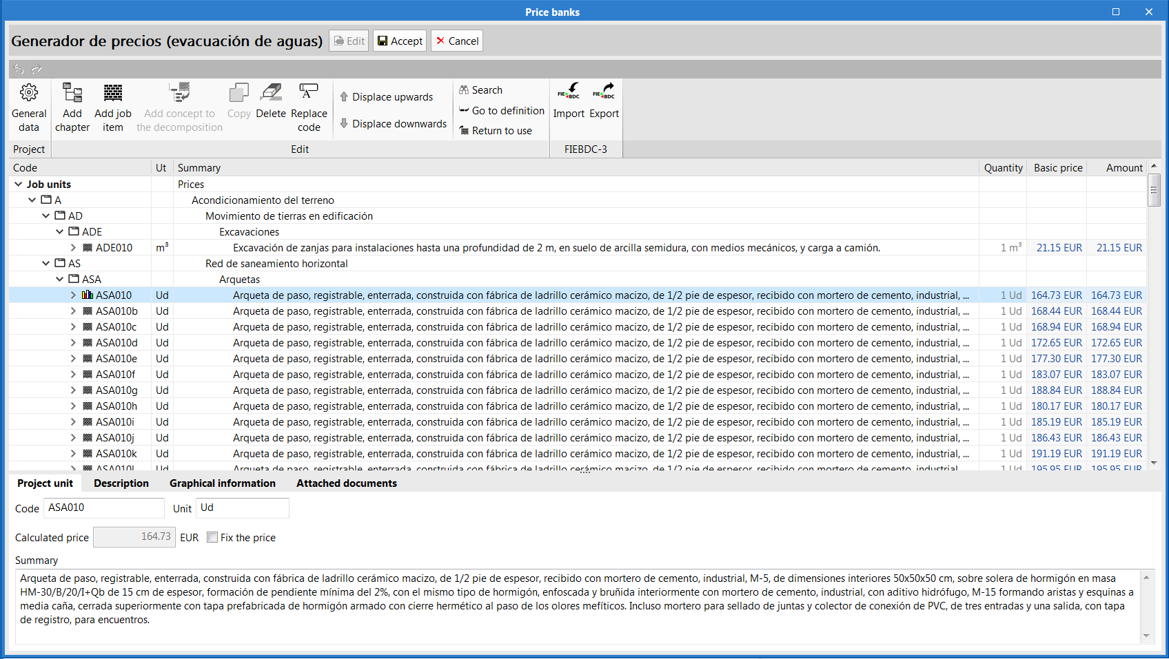
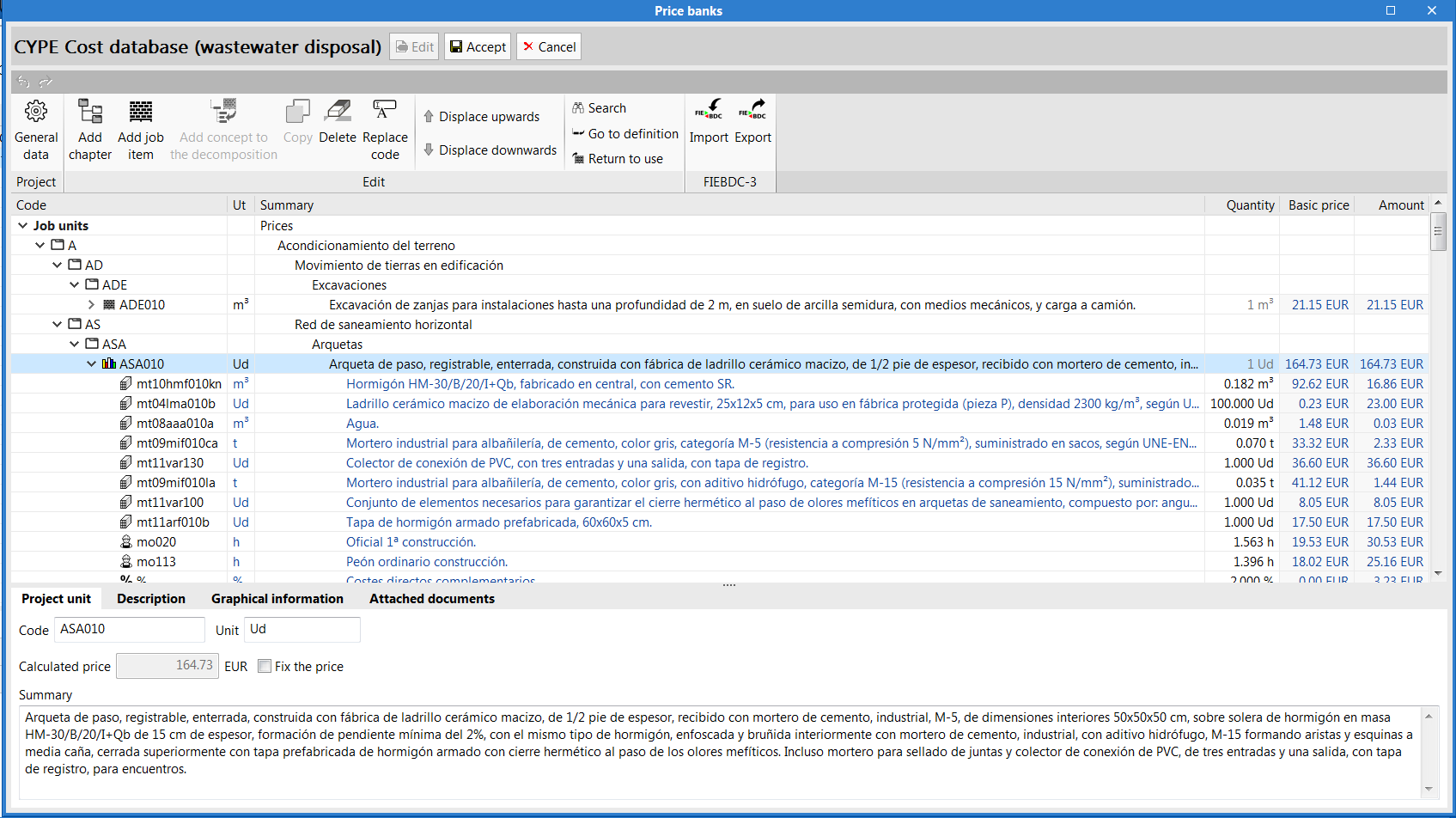
In order to enter project prices easily, users can import complete databases as well as individual concepts from cost databases that have been developed in accordance with the FIEBDC-3 standard (.bc3), such as the CYPE construction cost database Generador de precios.
A cost database and mapping example have been included for installation elements for most of the programs that have the bill of quantities tab. Remember that they are just examples and you can create your own mappings and cost databases.
The documents of the bill of quantities can be extracted in several types of reports (Quantities, Cost breakdown structure, Priced bill of quantities, Detailed priced bill of quantities, BoQ summary) and can be exported in HTML, DOCX, PDF, RTF and TXT formats.
The bill of quantities can also be exported, in "FIEBDC-3" format, from the "Bill of quantities" tab of each program, to then be used in cost management programs such as Arquimedes.
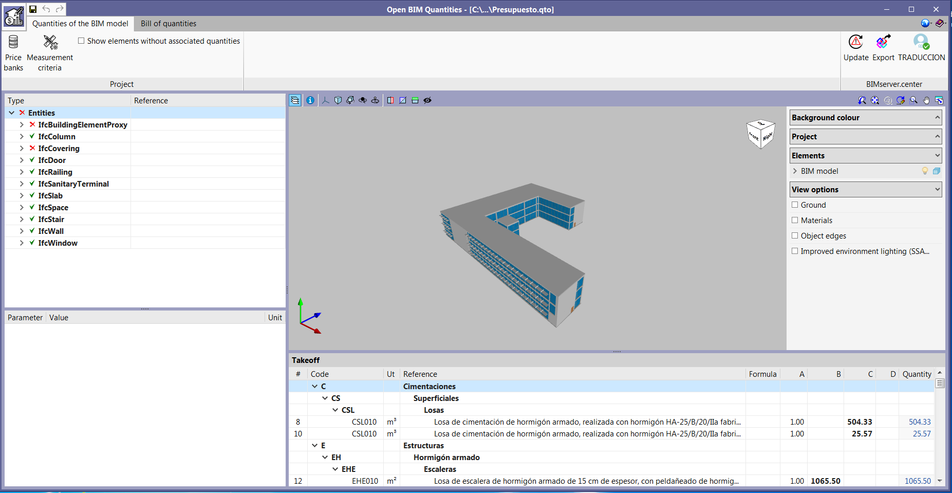
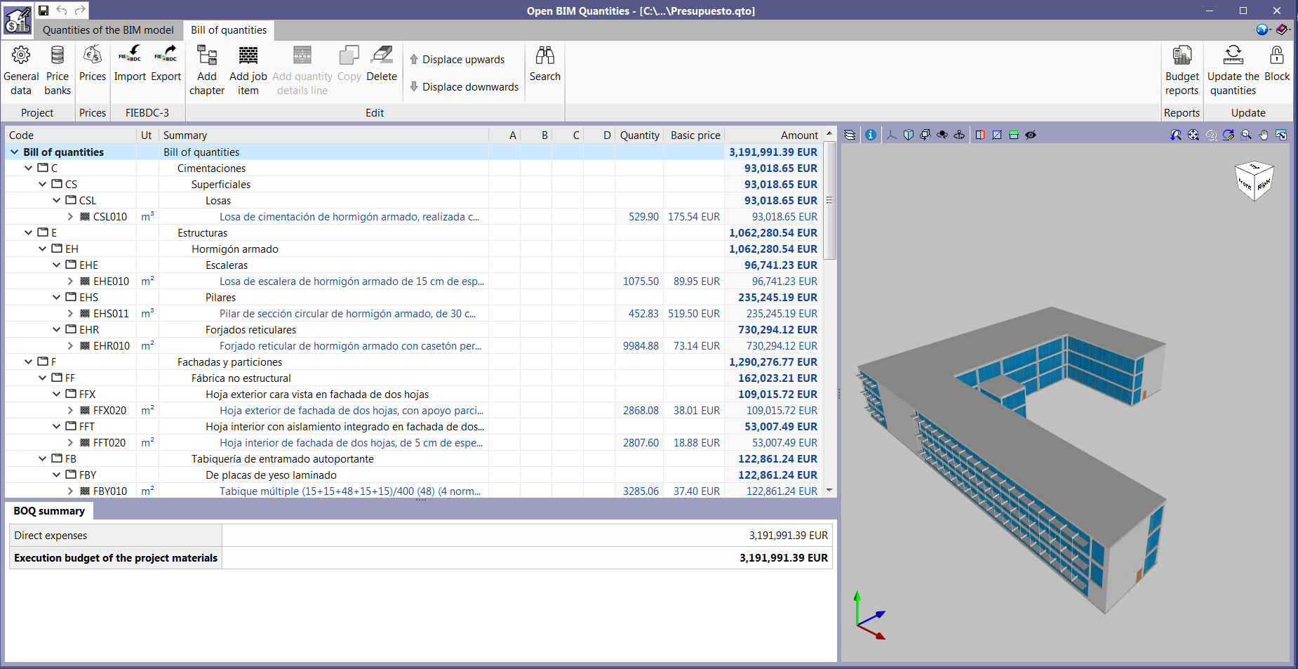
The "Bill of quantities" tab is also included in "Open BIM Quantities" (new program of the 2020.e version). Unlike other applications that include the "Bill of quantities" tab, "Open BIM Quantities" allows users to extract the quantities from BIM models that have been defined using the IFC standard (in their "Quantities of the BIM model" tab) . The other programs extract it from the installation that has been introduced in the program itself. Once the quantities have been extracted, the process to generate the bill of quantities in "Open BIM Quantities" is carried out in its "Bill of quantities" tab, as is done with the other Open BIM applications that contain the tab.
Update notification for CYPE applications that have been downloaded from the BIMserver.center platform
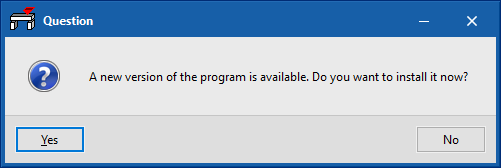
It may occur when users execute a CYPE program from the previous version (2020.d), which was downloaded from the BIMserver.center platform, that a message may appear alerting them that a new version of the program is available and requests if they wish for it to be installed.
If the update process is accepted when a program is executed, it is possible that the message may remain hidden behind the initial program window (project selection). To bring the message to the foreground, close the program, move the program window or change the active window using the "Alt + Tab" key combination.
In future versions, the update message will appear if the version to be updated is 2020.d or later
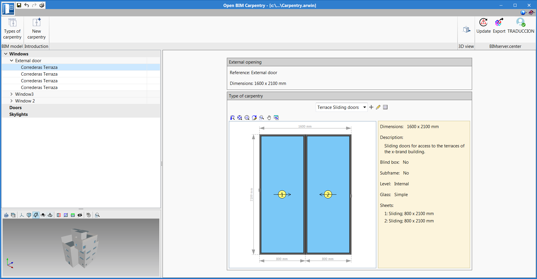
Organisation of the element panel (windows, doors and skylights)
The side panel containing the elements that are entered in the program (windows, doors and skylights) has been organised. Now, they are grouped by type and subtype in dropdown menus.
Column and beam tags
In the 2020.e version, the management of column and beam tags has been implemented. In the portal frames, column detail and column schedule drawings, users can select frames and columns depending on the tags that have been assigned.
Users can access the "Tags" panel from the "Groups" menu in the "Beam Definition" tab, where three options have been implemented:
- Assign
Users can assign tags to columns and beams. The list of tags can be managed from this option. Marked tags will be assigned to the elements that have been selected on the current floor. - Delete
Allows users to delete tags that have been assigned to columns and beams. Marked tags will be deleted from the elements that have been selected on the current floor. - Edit
Allows users to edit tags that have been assigned to an element.
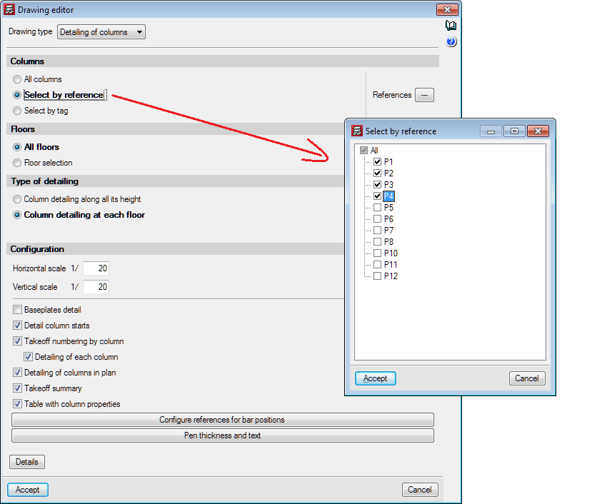
Selection of columns in "Column details" and "Column schedule" drawings
In the 2020.e version, users have the possibility to obtain the "Column details" and "Column schedule drawings" for columns that have been selected by reference.
Assign buckling and lateral buckling coefficients to steel and timber beams
Users can assign buckling and lateral buckling coefficients to steel and timber beams. This option allows users to assign different values to each beam.
This option is located in the Beam Definition tab (Beams > Other options > Assign buckling coefficients).
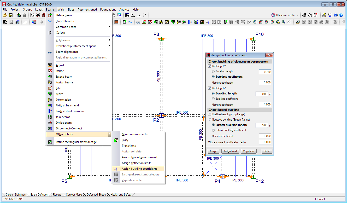
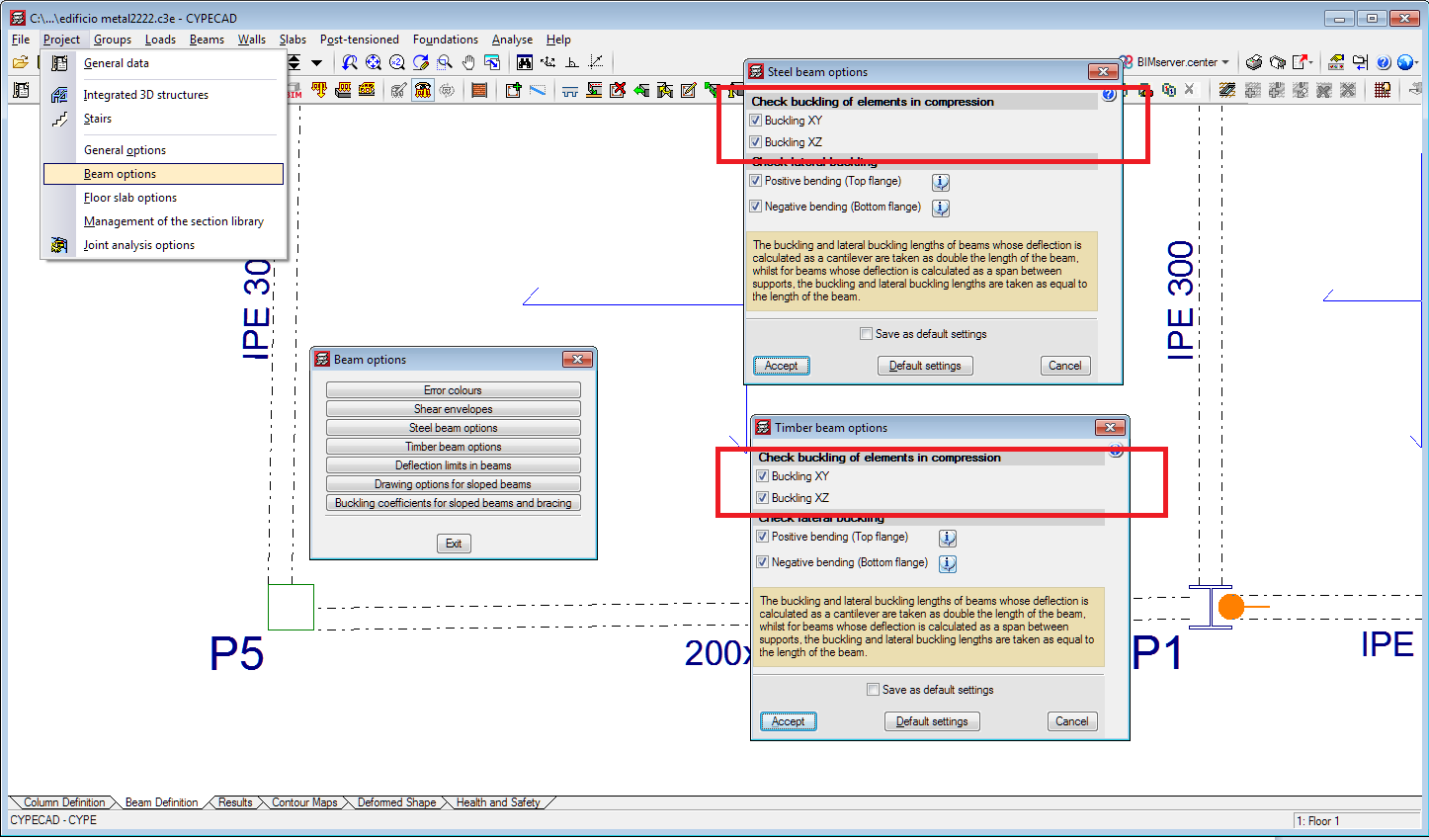
Activate or deactivate the buckling check for steel or timber beams that are subjected to compression
In the 2020.e version, an option has been implemented to activate or deactivate the buckling check for steel or timber beams that are subjected to compression in the XY plane and in the XZ plane (in CYPECAD only beams that are disconnected from the rigid diaphragm can be subjected to compression). In previous versions, compressed steel or timber beams were always checked for buckling.
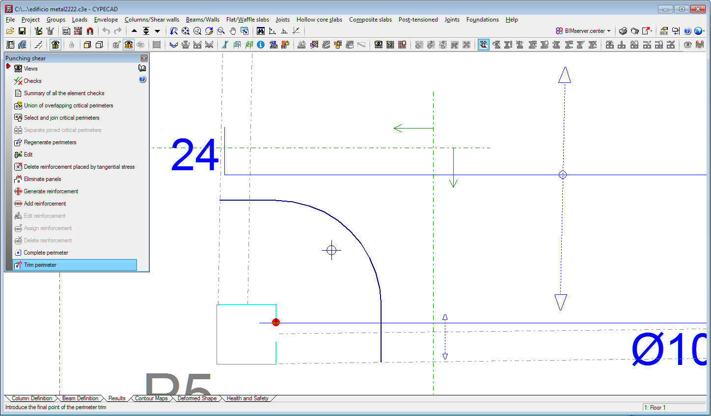
Edit the perimeter of the support for punching shear checks
In previous versions to the 2020.e version, users could complete or trim the critical perimeter and reinforcement perimeter in the punching shear check. As of the 2020.e version, it is also possible to complete or trim the perimeter of the support.
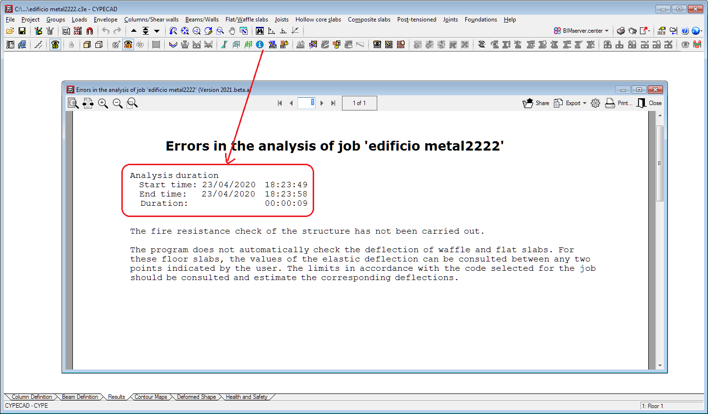
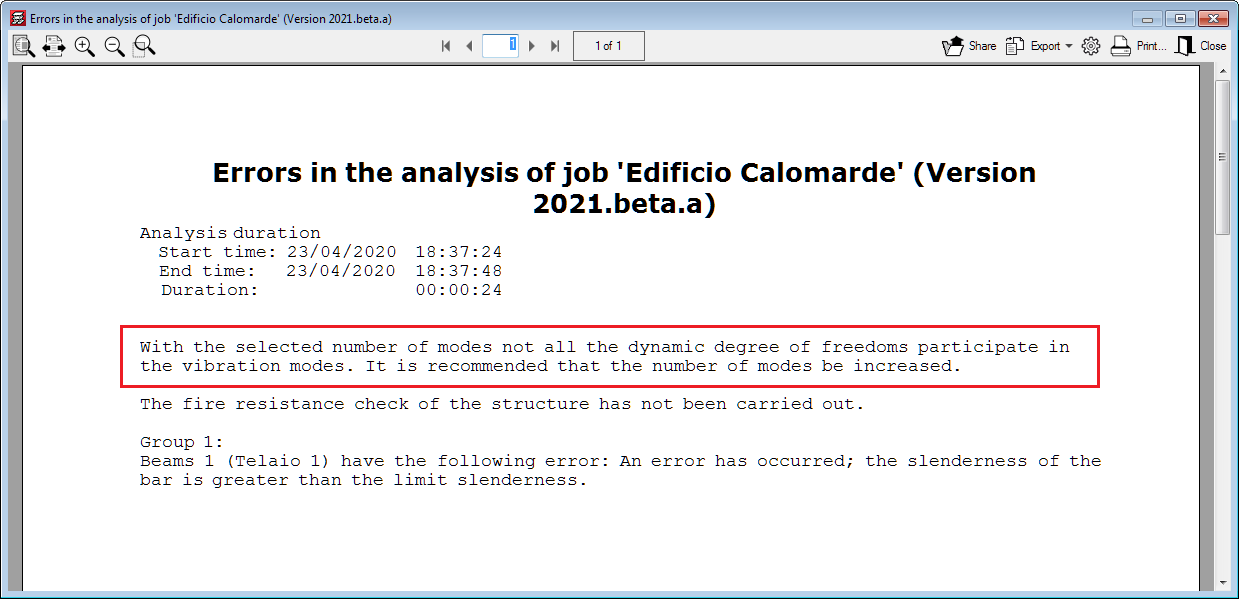
Analysis duration in the final report
As of the 2020.e version, the start time, end time and duration of the analysis is added to the final design report.
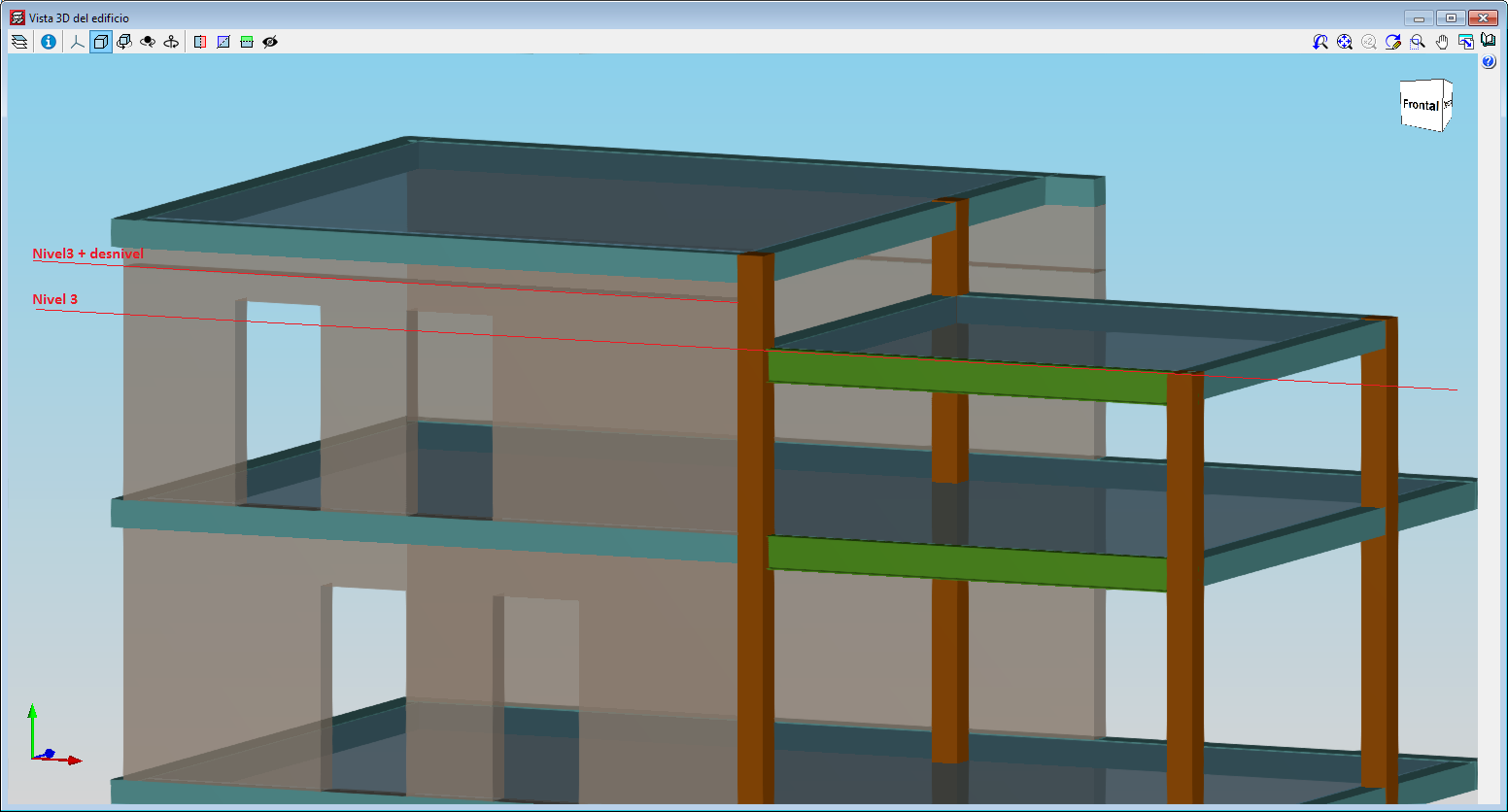
Assign elevation differences to intermediate floors of walls
With this improvement, which is included in the "Sloped floor slabs/ El. Changes" option in the "Walls" menu, users can define an opening in a wall when the upper elevation of the opening is higher than the elevation of the floor. This improvement is useful when intermediate floors have to be defined in the project, such as roof slabs at different heights.
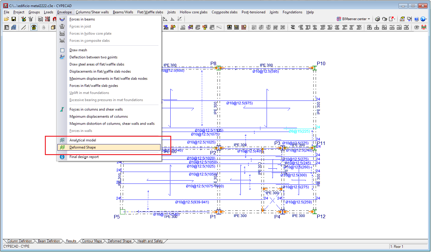
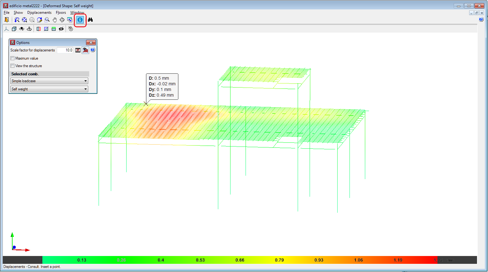
Consult displacements in the 3D view of the deformed shape
In the 2020.e version of CYPECAD, users can consult results in the 3D view of the deformed shape. This window is accessed from the "Deformed shape" tab, and also (as of the 2020.e version) from the "Deformed shape" option of the "Envelopes" menu of the "Results" tab.
By activating the "Consult" button in the window of the 3D view of the deformed shape, the program displays the displacement values of the points of the structure on which the mouse cursor is placed.
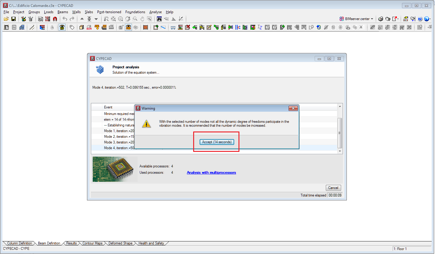
The analysis is not interrupted with warnings requiring users' approval
In previous versions, certain warnings interrupted the analysis until users accepted them. As of the 2020.e version, these warnings are displayed with a twenty second wait before closing automatically. In any case, these errors appear in the final report. This improvement allows the analysis to continue and finish when these warnings appear without the need for users to be on the lookout.
Correction of errors at wall intersections
Errors related to specific geometries at wall intersections at the same level and with walls introduced on other walls, which interrupted the analysis, have been corrected.
Check of columns and timber bars with circular sections for the "CIRSOC 601" and "ANSI/AWC NDS-2015" codes
The 2020.e version includes the check of columns and timber bars with circular sections for the following design codes:
- CIRSOC 601
- ANSI/AWC NDS-2015
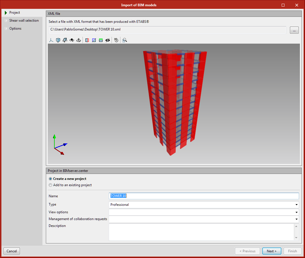
StruBIM Shear Wall projects based on ETABS® structural models
As of the 2020.e version, "StruBIM Shear Walls" can interpret ETABS® structural models from the "ETABS 2016" and "ETABS 18" versions (ETABS® is a registered trademark of Computer & Structures, Inc). "StruBIM Shear Walls" obtains the information that is required to design the shear walls from this structural model.
"StruBIM Shear Walls" users can import the structural model from ETABS® using two methods:
- Import of the structural model of an Open BIM project
When "StruBIM Shear Walls" creates a new project, users can connect to an Open BIM project from which the ETABS® structural model can be selected and imported (if it has been included previously in the project using "StruBIM Uploader"). - "StruBIM Uploader" option included in "StruBIM Shear Walls"
In the project selection and creation panel of "StruBIM Shear Walls", the option "StruBIM Uploader" has been implemented. This option asks users to select a file in XML format that has been produced with ETABS® software, uploads the ETABS® structural model to an Open BIM project of the BIMserver.center platform (the same way "StruBIM Uploader" would do) and obtains from it, the information that is required to carry out the design of the shear walls.
Improvements in the design process
In the 2020.e version, the design process has been improved to obtain more optimised reinforcement.
Work simultaneously on several projects
The possibility to open CYPECAD MEP several times simultaneously has been implemented. This way, users can work on multiple projects at the same time. This option was already available in other CYPE applications.
"Match" tool
The "Match" tool has been implemented to copy parameters from one load to another. Simply select the load to be copied, then the destination loads. This option is located in the "Edit" section of the toolbar.
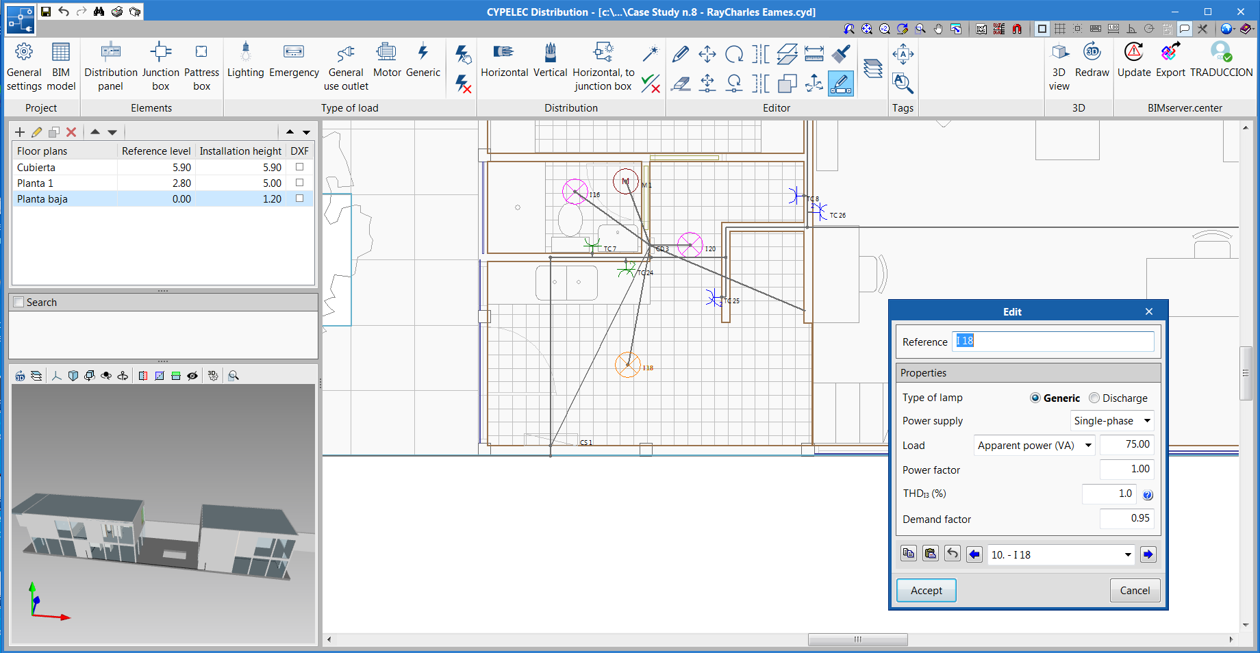
Series editing of loads that have been entered
The "Edit series" tool has been implemented, with which users can edit, in series, loads that have been introduced. This tool is located in the "Edit" section of the toolbar.
If the "Edit series" tool is active, when any element of the single-line diagram is edited, for example, a lighting point, the editing panel that appears has a lower bar that allows users to scroll along (backwards and forwards) all the loads that are present in the electrical distribution. This tool also allows users to copy the editing parameters of the load that is being displayed and paste them to another previous or later load.
The "Edit series" tool is designed to edit and view load characteristics more quickly.
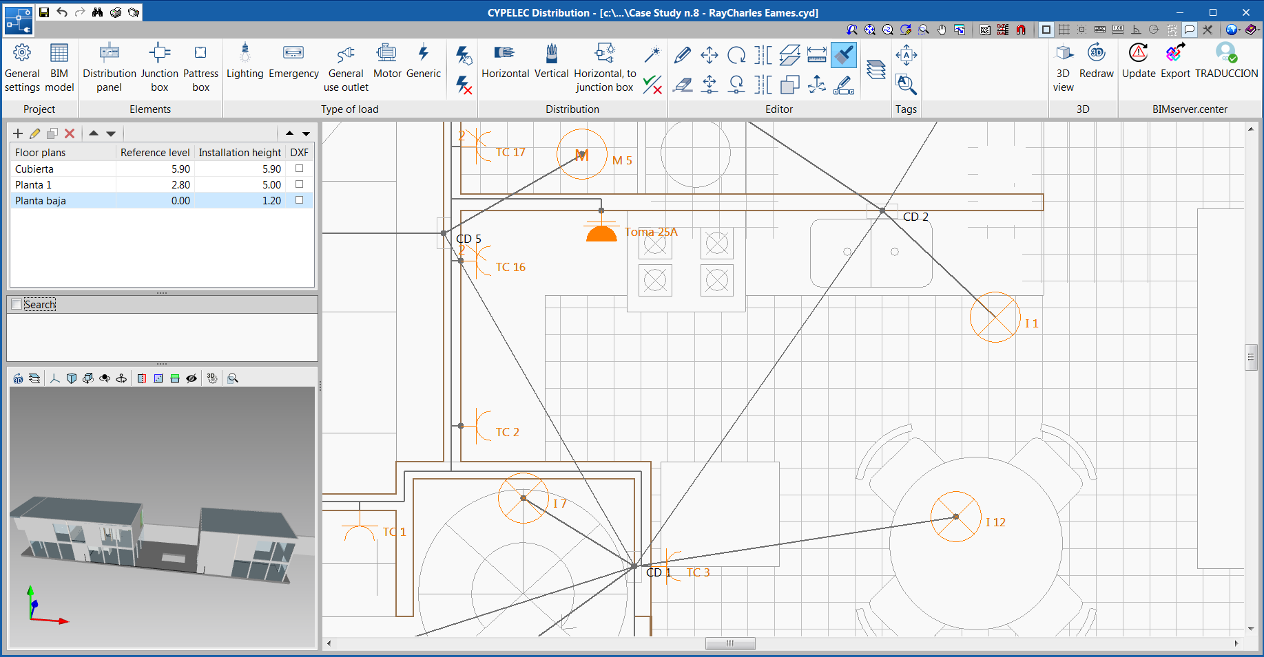
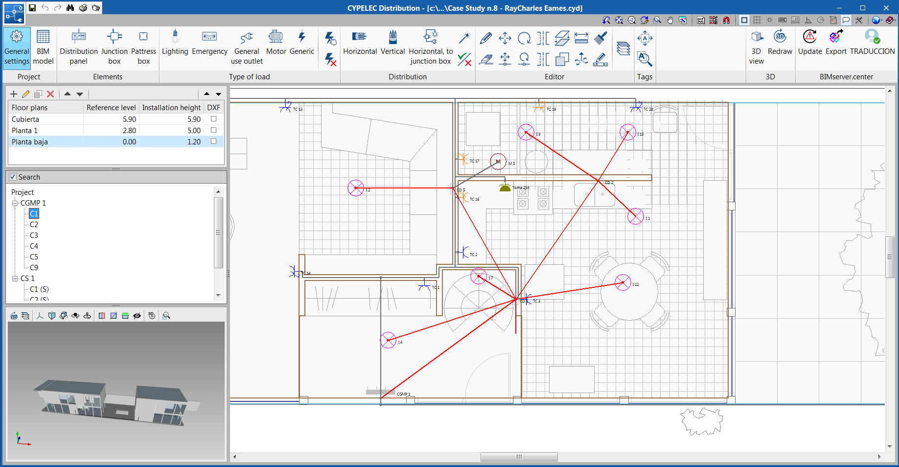
View of the circuit distribution
A side tool has been implemented, which users can use to search for panels and subpanels that have been entered, and their respective circuit distribution.
Once the analysis has finished, the tool allows users to mark the corresponding circuit to view its distribution on plan.
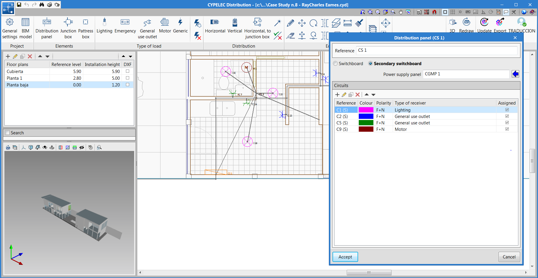
Assign power supply panel of the electric subpanel
The edit panel of the secondary switchboard is completed with the designation of its power supply panel. The power supply panel can be the main switchboard or another secondary panel.
This designation is mandatory and with it, the program detects that the panels are effectively interconnected and hence, there is a greater control of the proposed electrical distribution.
Tool for the automatic distribution of loads to the junction box
A typical electrical distribution is where certain lighting loads are connected to the same junction box. To speed up this process, a tool called "Horizontal, to junction box" has been included in the "Distribution" block of the toolbar.
The tool works by selecting the loads that are supplied from the same junction box, then click on the right mouse button and then select the junction box itself. The program will generate the connection distribution (star shaped), both horizontal and vertical, between each load and the junction box.
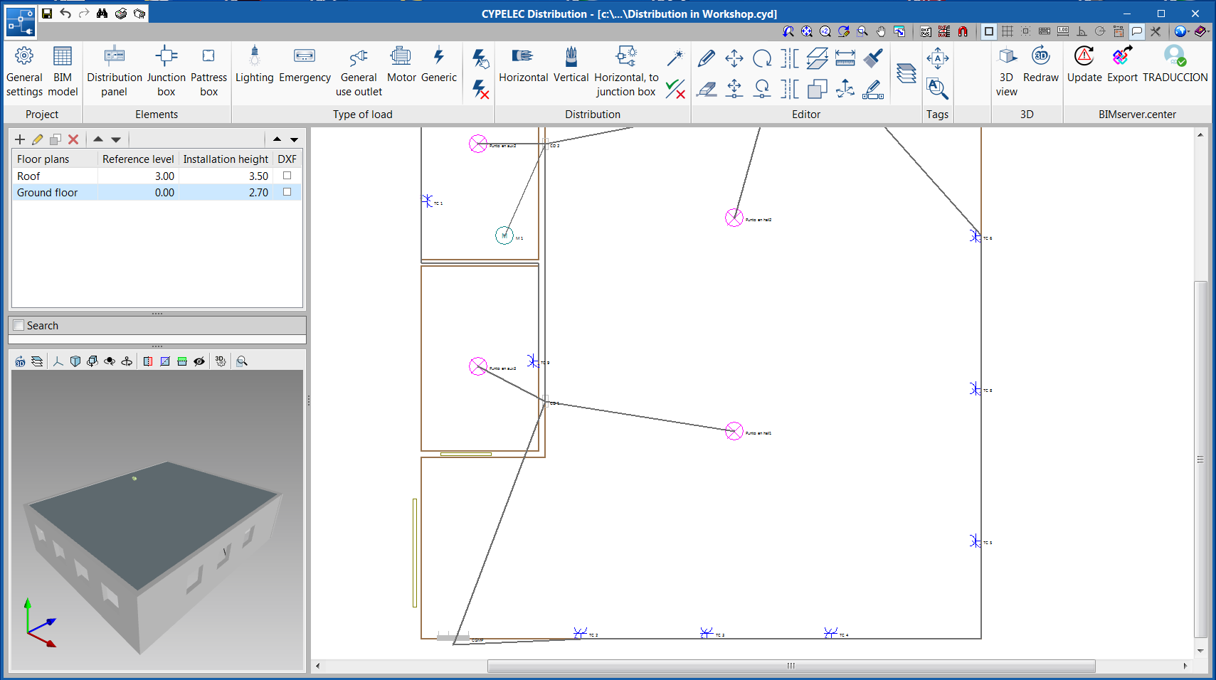
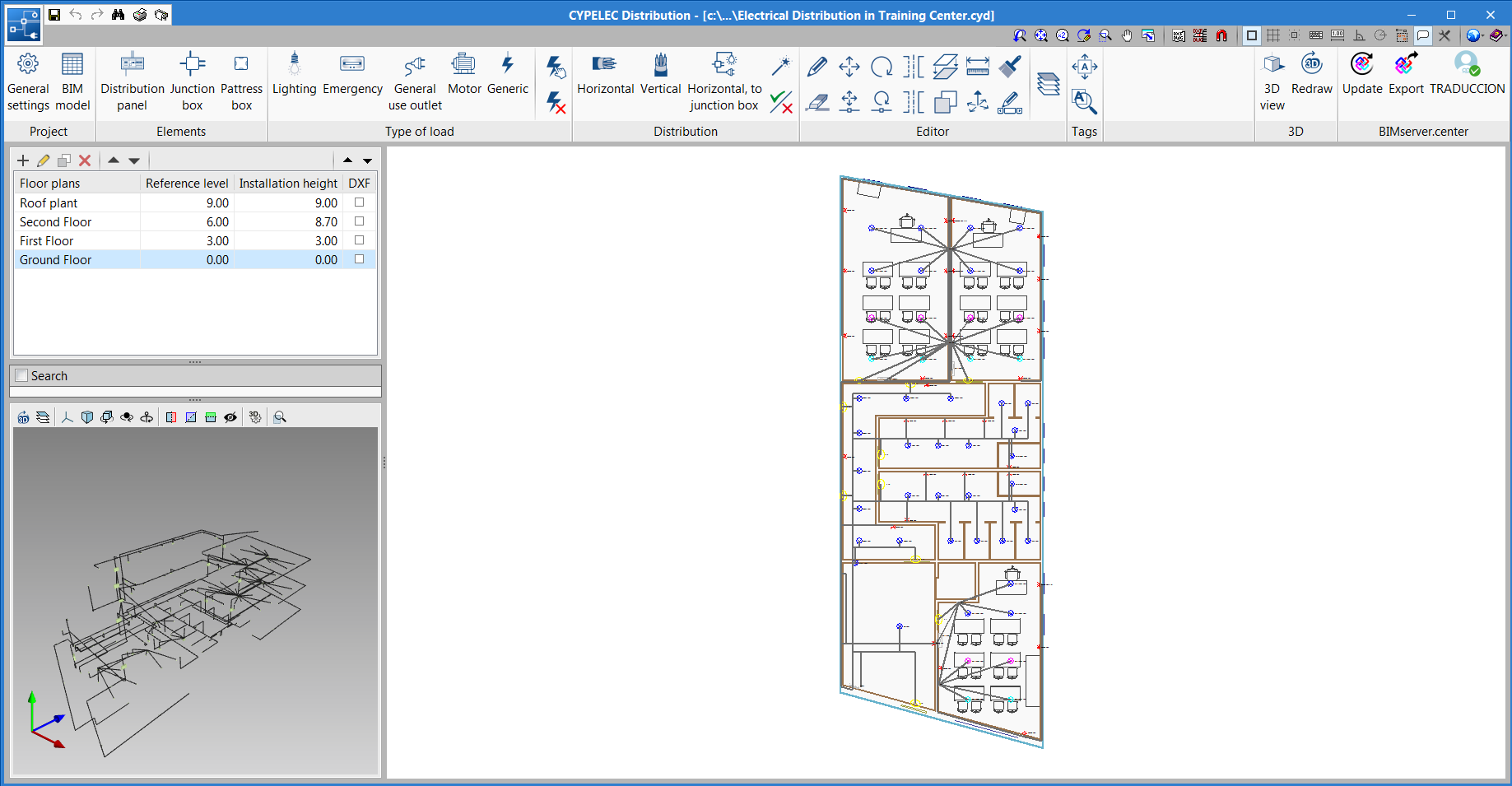
New project example (Training Center)
A new project example has been included: "Electrical distribution in training center". This project represents the electrical distribution in a training center that contains a single switchboard, and several secondary panels.
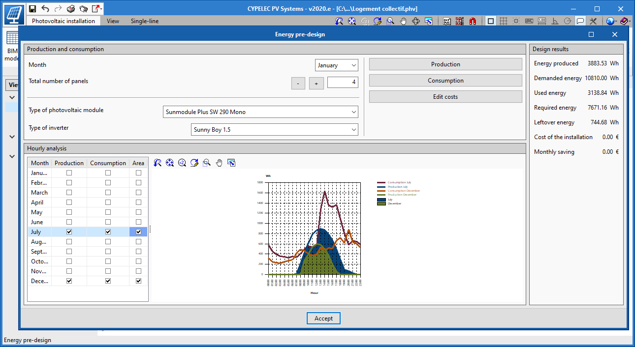
View consumption and generation graphs
In the "Energy pre-design" window, it is possible to view all the generation and consumption graphs. This functionality makes it possible to quickly compare the corresponding energy consumption and generation for the whole year.
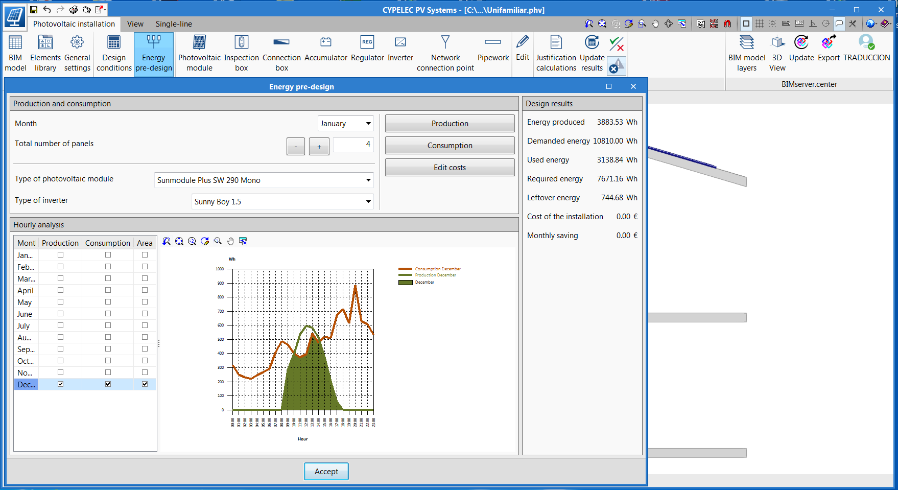
View the intersection between consumption and generation graphs
In the "Energy pre-design" window, it is possible to view the intersection between the generation and consumption graphs, showing the contribution of the energy that is generated by the photovoltaic installation with respect to the actual energy consumption in a given month.
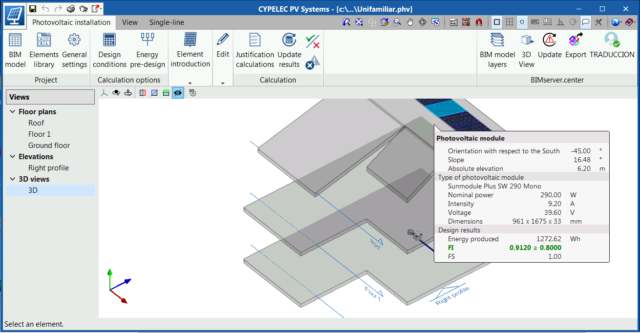
Extended information in the tooltips of the photovoltaic module and inverter
In the tooltips of the photovoltaic module and inverter, information has been added to the design results, so users can quickly analyse the results of the design that has been carried out.
Added to the tooltip of the photovoltaic module is:
- The energy that is generated by the indicated module after the analysis.
- The orientation and slope factor and whether it complies with the requirements or not.
- The shade factor.
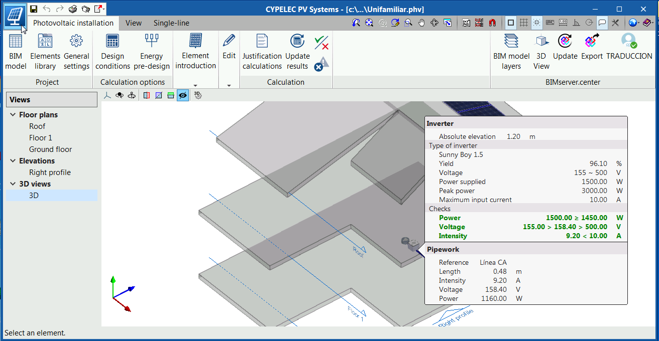
Added to the tooltip of the inverter is:
- The power of the inverter and whether it is sufficient for the peak power that is generated.
- The input voltage of the inverter and if it lies within the admissible values.
- The input voltage of the inverter and if it is lower than its admissible current.
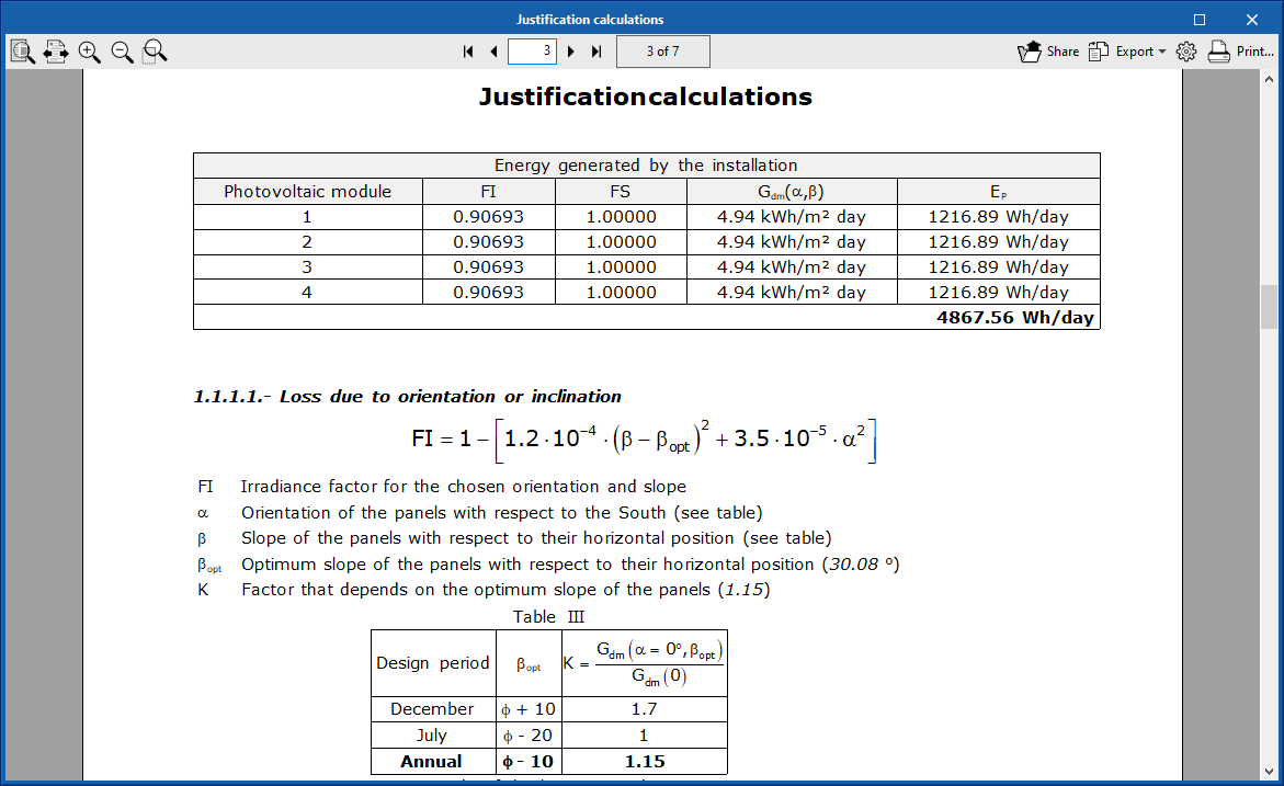
Justification of the losses by temperature of the photovoltaic module
The temperature losses section of the justification report is complemented with a table specifying, for each photovoltaic module, the cell temperature that is reached and the temperature loss due to it.
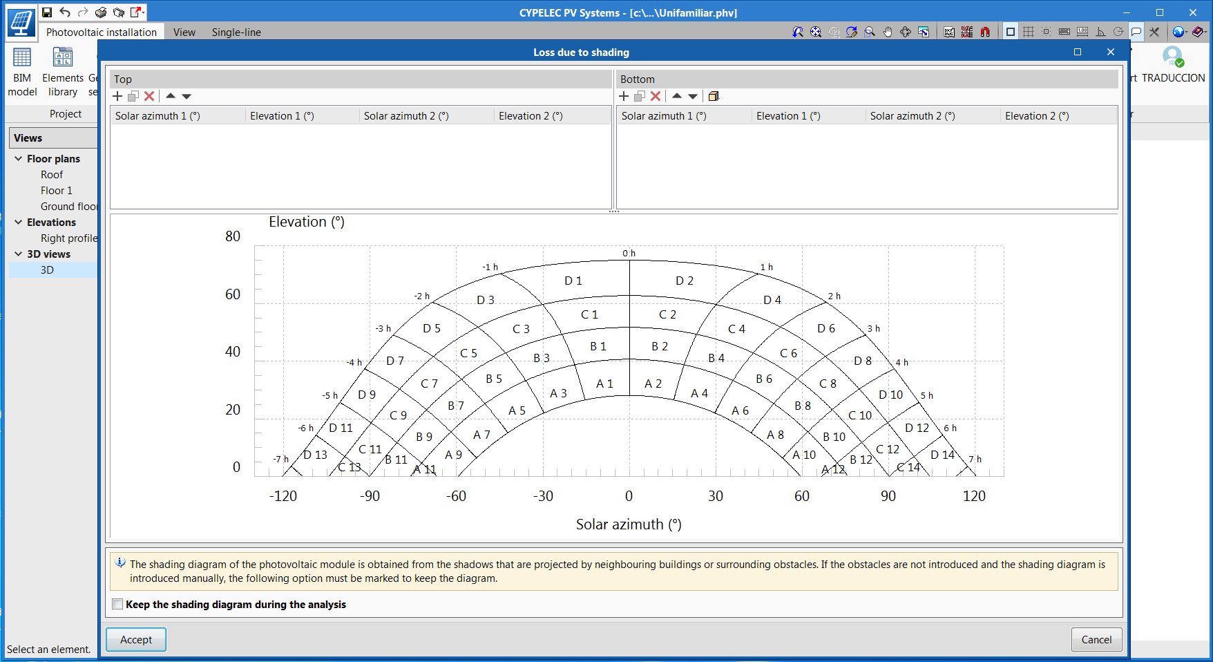
Possibility to save the shading diagram that has been edited manually
Users can save shading diagrams that have been entered manually. To do so, the option "Keep the shading diagram during the analysis" has been created. If this option is active, the shading diagram that has been entered manually will be saved and losses caused by shadows cast by nearby buildings or other surrounding obstacles will be ignored.
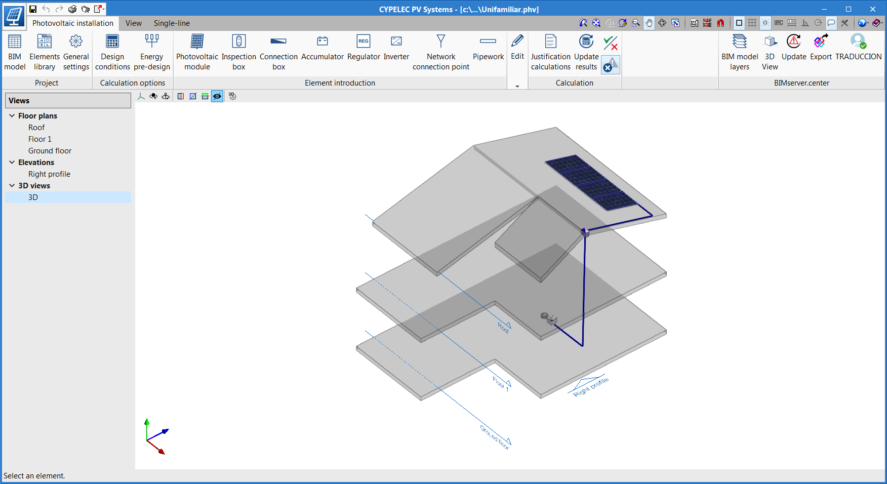
New project example for a single-family home
A new project example of a photovoltaic installation for a single-family home has been added, with four photovoltaic modules facing southeast.
Accessories and valves
The hydraulic analysis of singular losses produced by accessories and valves has been included in CYPEFIRE Hydraulic Systems. This new feature includes the following program updates:
- Accessories and valves catalogue
Two new receivers have been added to the "General options" panel, to introduce new accessories and valves.
A series of accessories and valves has been added by default for each design code.
As can be seen in the image, to create a new element, from either catalogue, simply introduce a reference and the associated loss coefficient of the element, to carry out the hydraulic analysis.
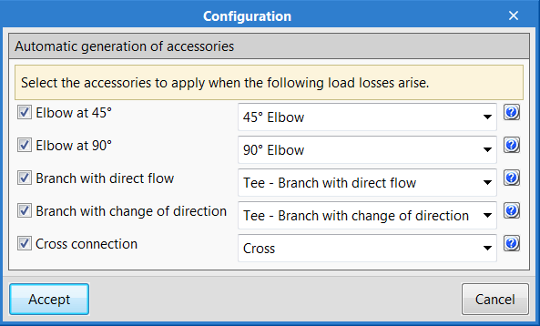
- Automatic generation of accessories
To optimise the time required to analyse the project, the "Automatic generation of accessories" option has been introduced in the "General data" panel. Using the automatic generation, the software recognises, depending on the distribution of the network, the following nodes and applies the load loss that is selected by users.
- 45º elbow
- 90º elbow
- Tee – Branch with direct flow
- Tee – Branch with change of direction
- Cross
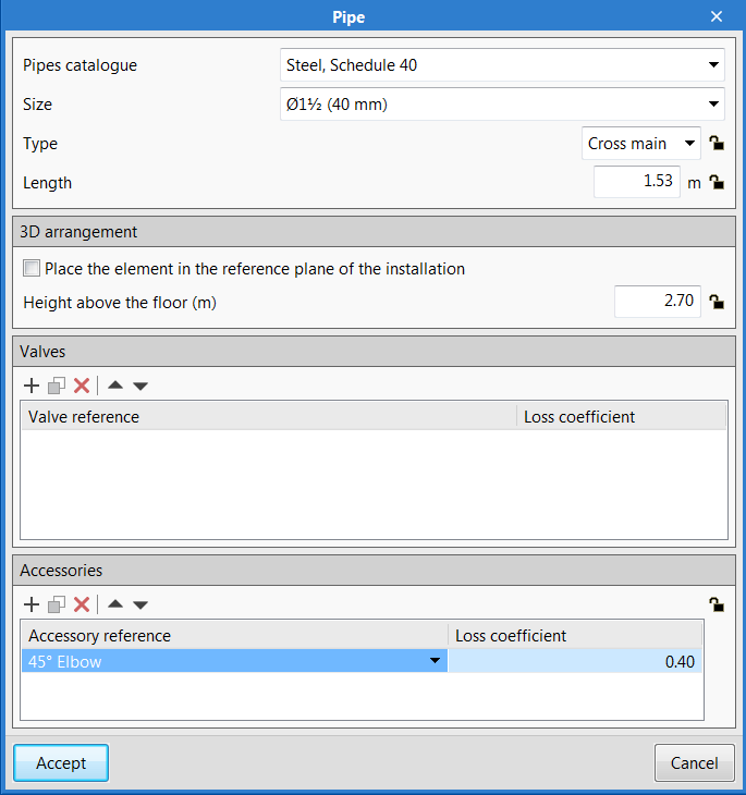
- Introduction of singular elements
Accessories and valves can be introduced manually on the pipes of the project. As can be seen in the image, accessories are blocked for the automatic generation, when they have been introduced manually.
"CYPEFIRE Hydraulic Systems" includes the load loss of the outlet pipe, i.e., for two pipes that are connected by a 90º elbow, the application will apply the loss at the outlet pipe, in the direction of the flow of the water.
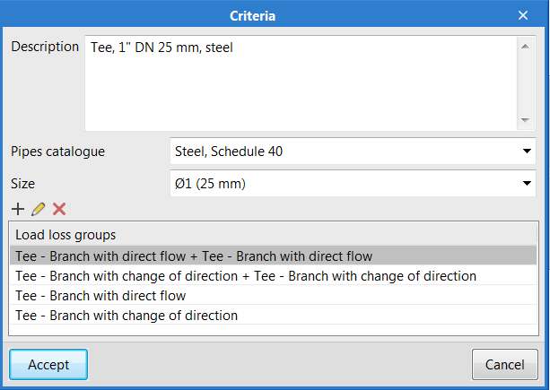
- Measurement criteria
A tool has been included in the "General options" panel which can be used to measure all the load losses that have been introduced in the installation. For these criteria, users must define:
- Description of the measurement
- Material of the element
- Load loss groups
"Bill of quantities" tab
In the 2020.e version, the "Bill of quantities" tab has been added in "CYPEFIRE Hydraulic Systems". Now, users have tools that can be used to generate and manage the bill of quantities of the elements that have been introduced in the program.
More information on this new feature can be found in the "Bill of quantities" tab in project phase Open BIM applications section, which affects several CYPE Open BIM programs.
New material for pipes: Polypropylene
As of the 2020.e version, users can define pipes in "CYPEFIRE Hydraulic Systems" that are made out of polypropylene.
This material has a table of nominal diameters that is different to those of the other materials that are included in the program. Therefore, once a pipes catalogue has been generated with this selected material, it will not be necessary to change the material of the catalogue.
Export attached documents
"CYPEFIRE Hydraulic Systems" exports the following files to the Open BIM project, as well as the 3D view of the installation of the extinguishing system:
- Project
- Material schedule
- Drawings
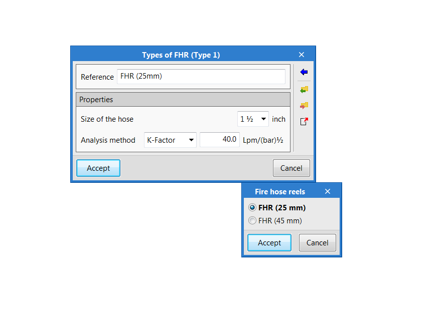
Predefined library of fire hose reels
En la versión 2019.g se incluyó en CYPEFIRE Hydraulic Systems el cálculo de Bocas de incendio equipadas. Ahora se incluye, como se muestra en la imagen, una biblioteca predefinida de tipos de BIE de 25 y 45 mm.
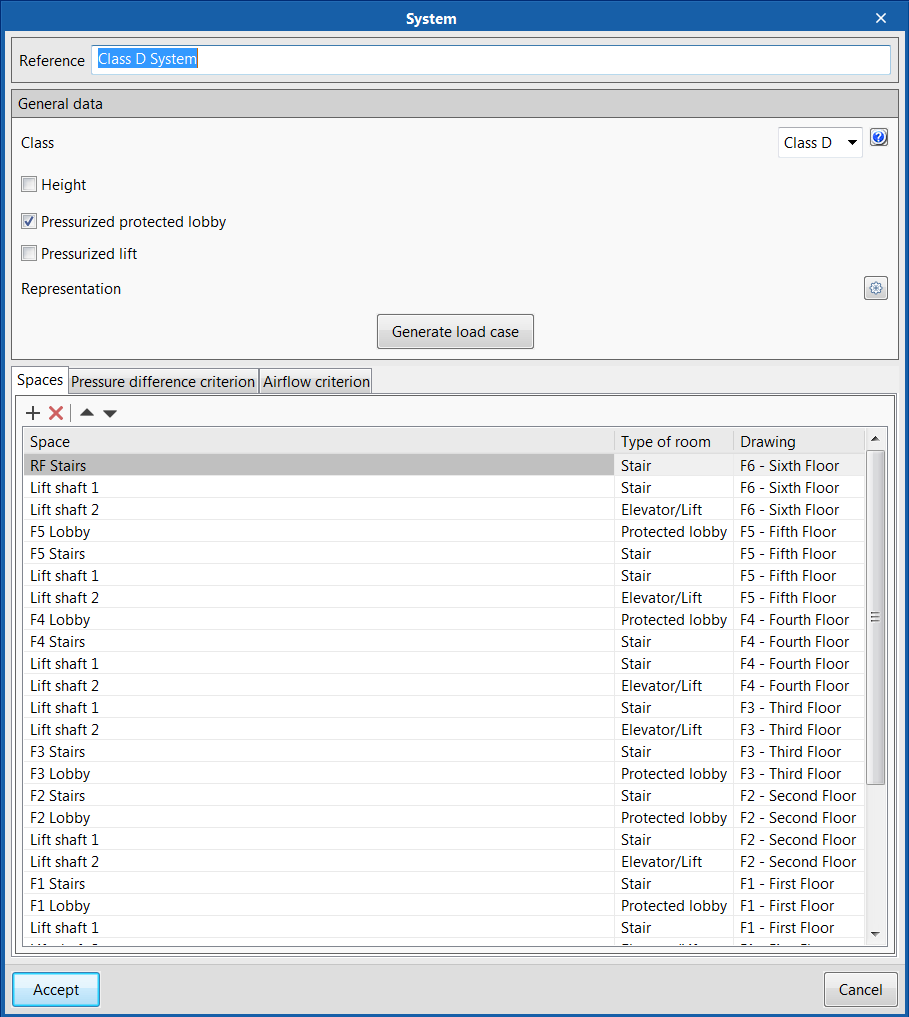
Design load case
As of the 2020.e version, "CYPEFIRE Pressure Systems" includes the "Generate load case" option when a pressure system is being entered.
This new tool generates the "door open" load cases, in accordance with that indicated in the EN 12101-6 standard.
Discharge grilles
The element "Grilles" has been included and can be checked in accordance with the design code. Grilles must be entered inside stairwells for the air discharge to be uniform.
For protected lobbies, a grille must be introduced for each one.
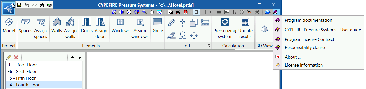
Program user guide
A "User guide" has been included in the application, and can be accessed from the Help menu. The guide includes basic information to get to know all the program tools and how they work.