The connection between Arquimedes and ArchiCAD® has been updated in the 2021.b version, to adapt it to import ArchiCAD® quantities from its new version, "ArchiCAD® 24 SPA". The connection with ArchiCAD® is a tool of the "Automatic quantity import from drawings and link with CAD programs" module.

Bills of quantities of Revit models. Use the same quantity extraction combination for entity links of the same family
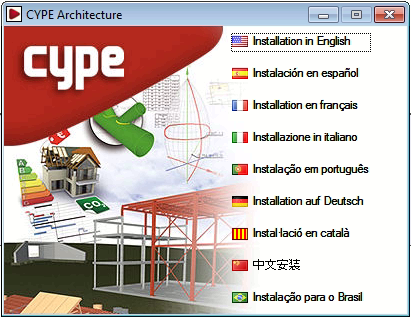
When, from the "Assign job items and quantity extraction" dialogue box, there is more than one link of several Types of the same Family to the same job item, the Match column allows users to use the same combination in entity links of the same family.
It is possible to match the sets of measurement rules of several entity links with a job item. When one of them is modified, the modification is applied to all the links of that job item. If the project already had different rules (quantity combinations) in the same job item, the program does not unify them; it only does so if one is modified.
All entities (Types) that are linked to a job item will have the same set of measurement rules because they refer to the same job item.
Bills of quantities of Revit models. Sets of measurement rules for openings
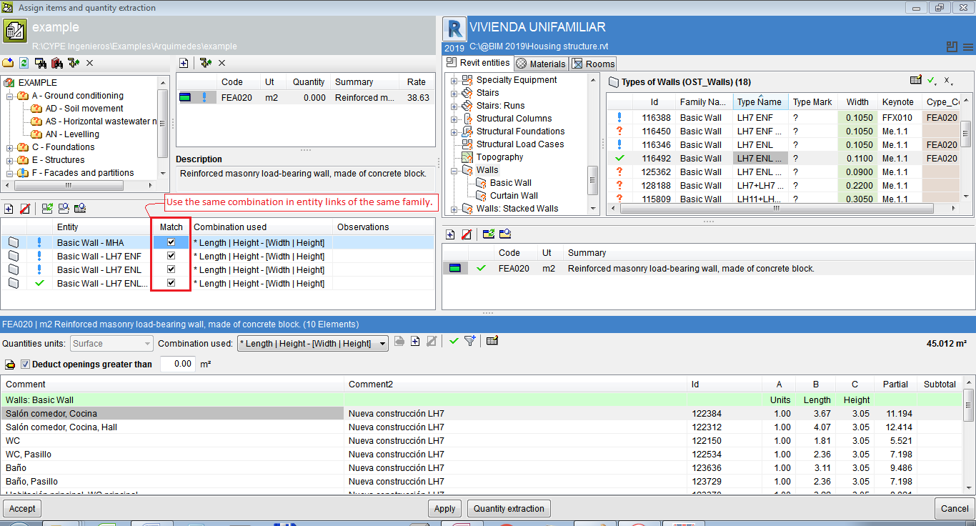
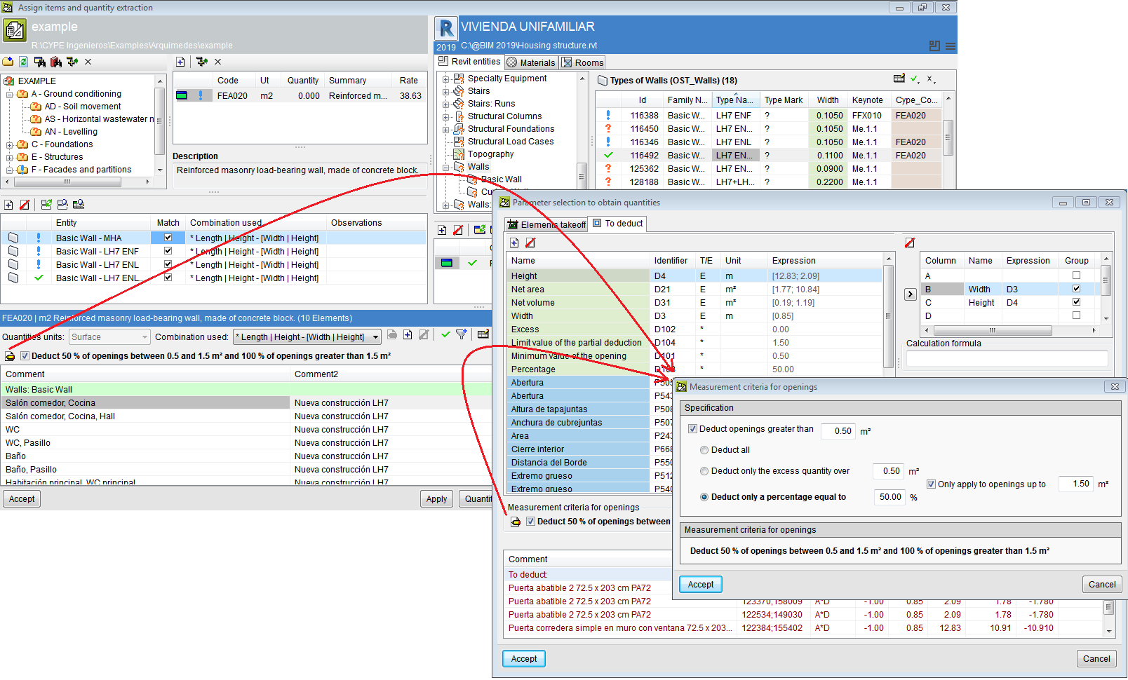
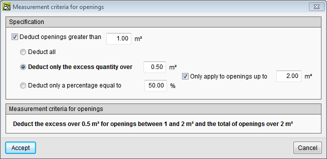
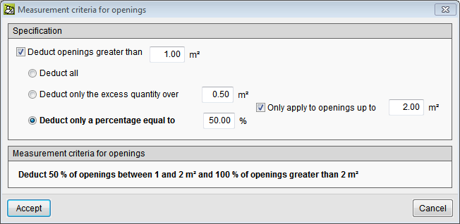
More options have been included within the "Deduct openings greater than" option to take into account more measurement rules, e.g. the possibility to deduct only one part (usually 50%) of openings that are smaller than a given value, and deduct them all if they exceed that value. The set of measurement rules for openings can be accessed using the "Set of measurement rules for openings" button. Here, users can:
- Deduct all openings that are greater than a given surface area.
- Only deduct the excess of a given surface area of openings, including deducting the excess of a given surface between two values and the total surface area of openings that is greater than a given surface area.
- Deduct a given percentage of the openings, or just deduct a given percentage of a surface area that lies between two given values and 100% of the openings of more than one given surface area.
IFC entity properties
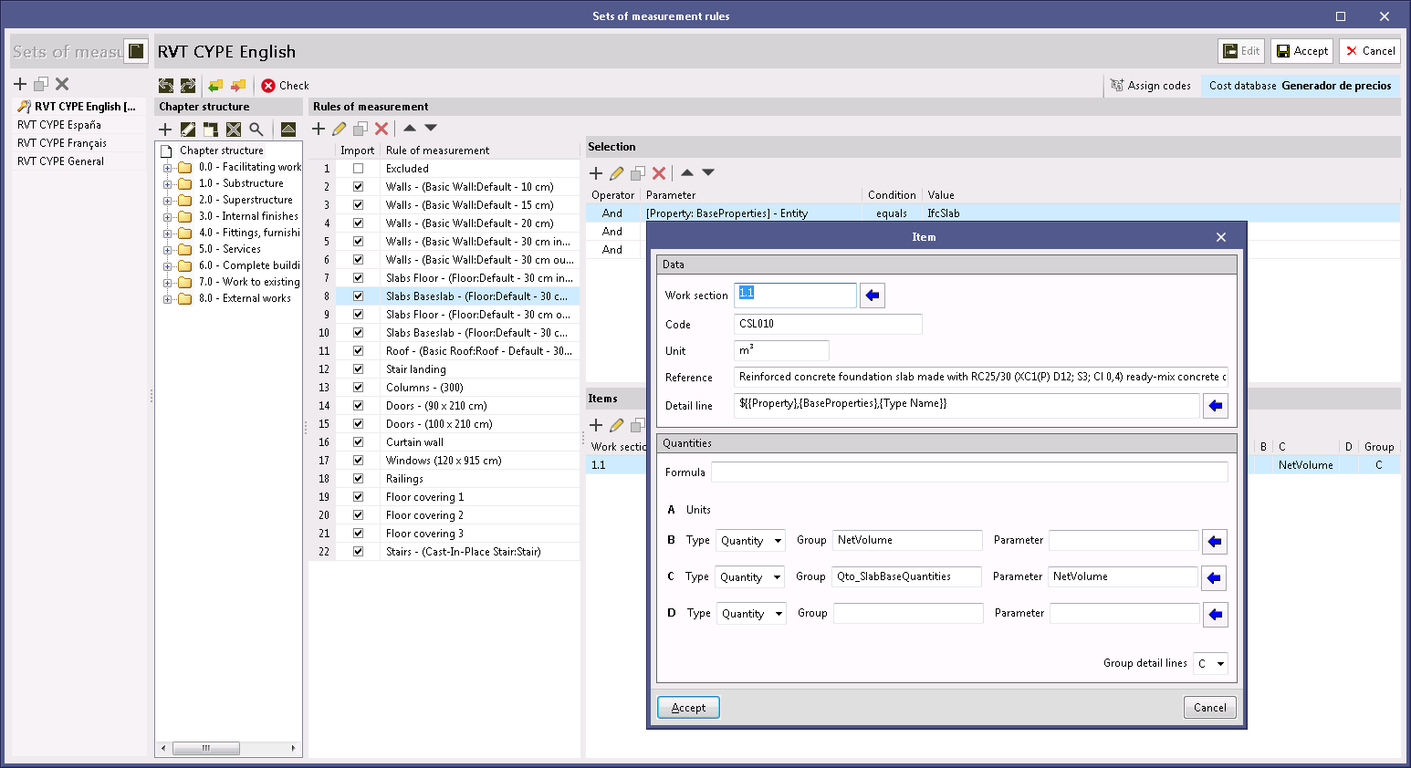
As of the 2021.b version, the properties of an IFC entity (IfcPropertySet) can be used in the "Set of measurement rules" of the project to generate the quantity take-off (variables B, C and D), as was already done previously with the quantities (IfcQuantitySet). The reason for this implementation is due to the existence of BIM modellers that are based on the IFC standard, which export quantity-orientated attribute groups as properties (IfcPorpertySet), instead of quantities (IfcQuantitySet). Now, in the job or project units panel of a "Measurement rule", users must indicate the type of attribute that is to be assigned to each variable, similar to what must be done when selecting the entities of the BIM model.
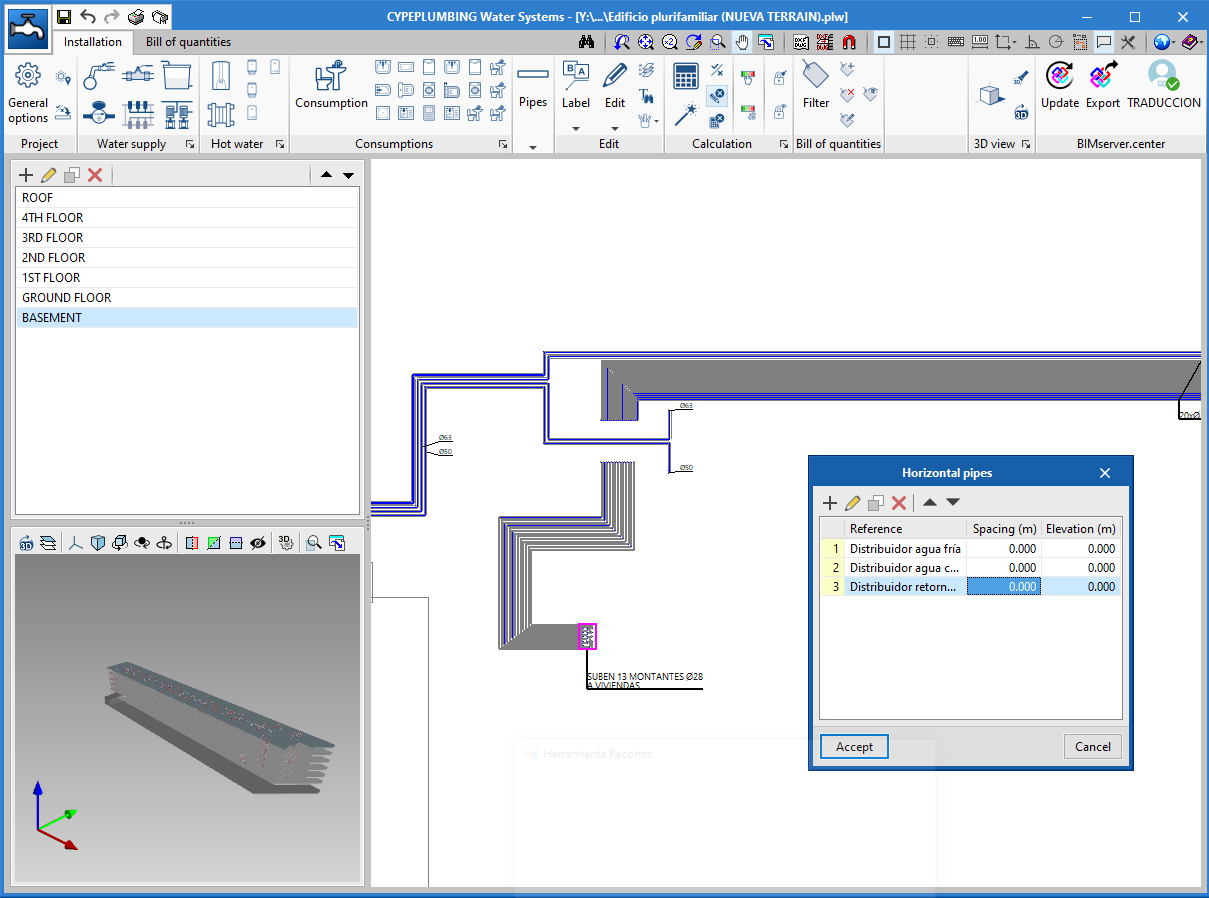
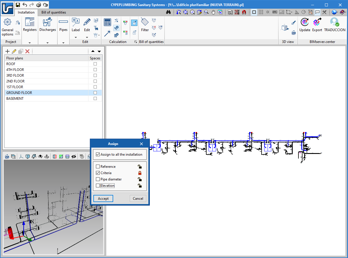
Simultaneous pipe entry
As of the 2021.b version, CYPEPLUMBING Water Systems allows users to enter several horizontal pipes that follow the same path. This tool also allows for them to be defined on several floors simultaneously.
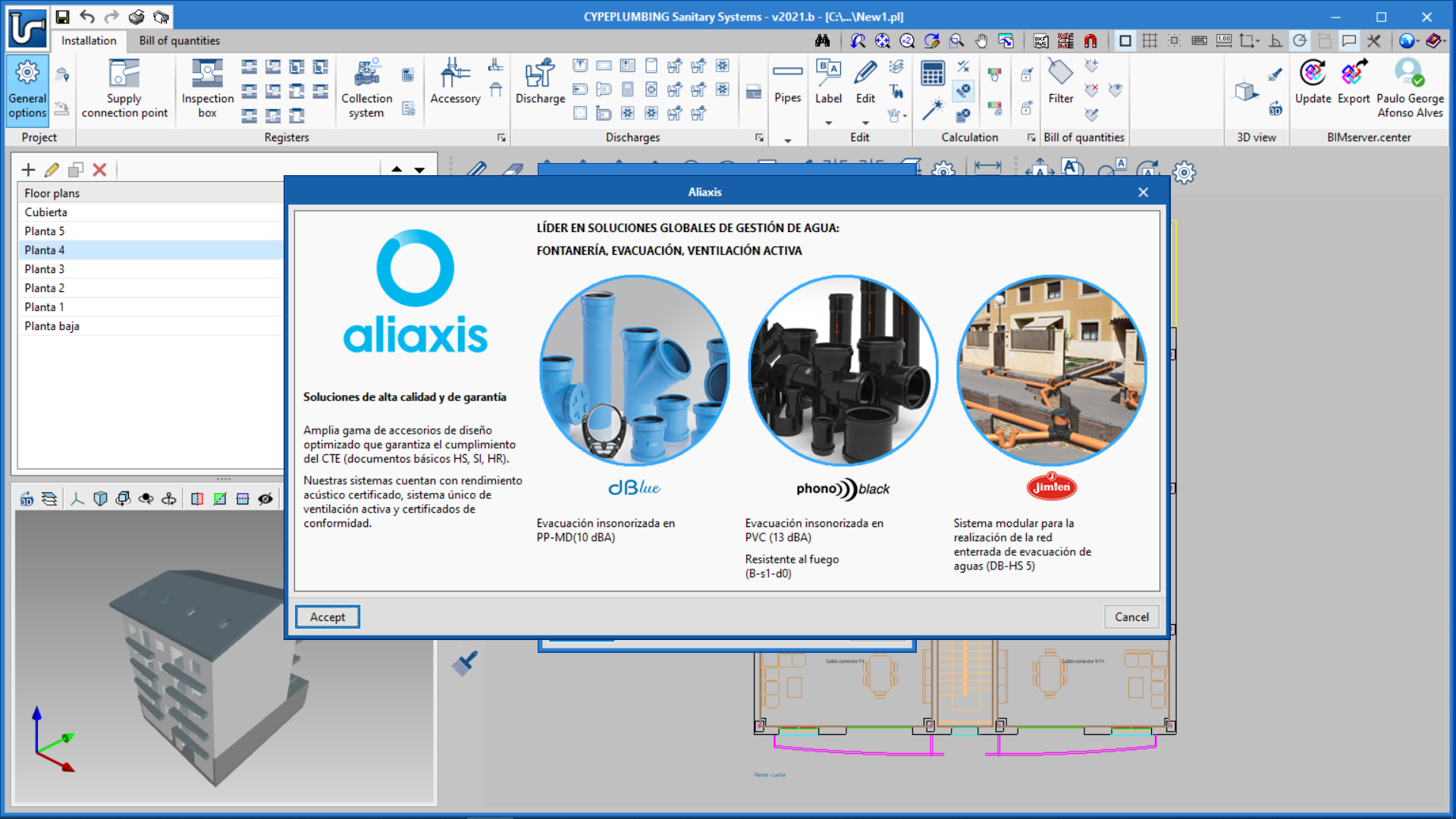
Addition of design criteria of the manufacturer aliaxis
As well as the addition of the aliaxis "Phonoblack" pipes catalogue, the design criteria for their pipes have also been implemented.
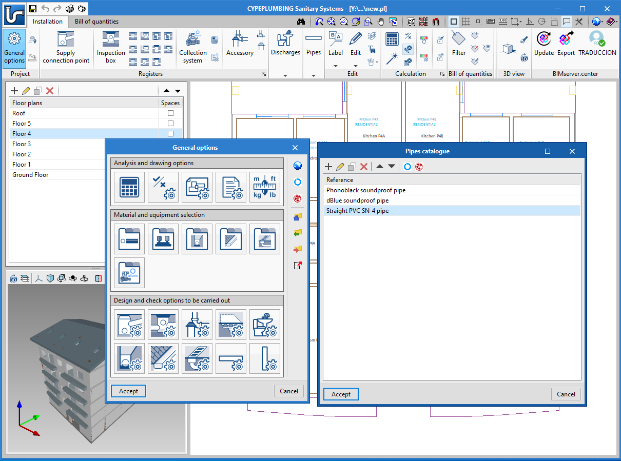
New aliaxis Phonoblack soundproof pipes catalogue
The 2021.b version of CYPEPLUMBING Sanitary Systems includes the Phonoblack soundproof pipes catalogue from the manufacturer aliaxis.
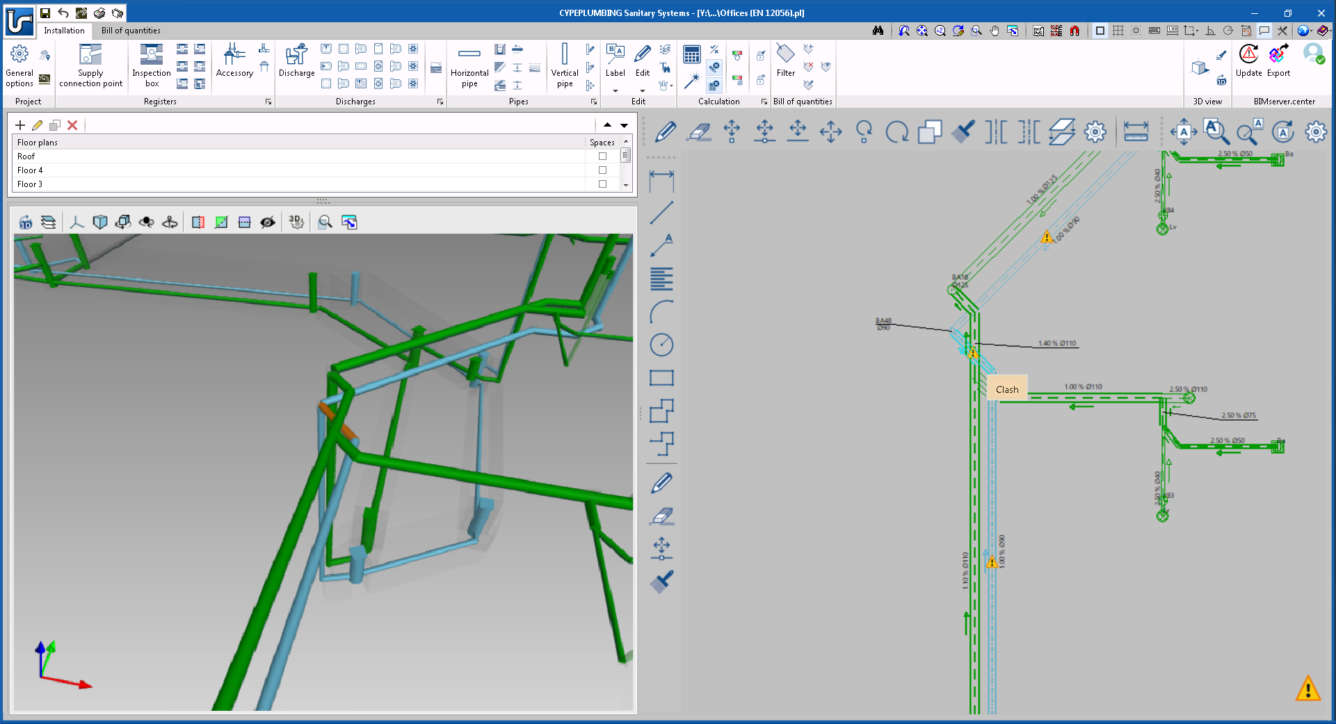
Clash detection of wastewater pipes
As of the 2021.b version, CYPELUMBING Sanitary Systems detects if there are any clashes between pipes of the different networks that have been included in the program.
New tools to manage blocked parameters
New tools have been included to manage blocked parameters.
Users can block the main parameters calculated by the program either globally or partially.
A tool has also been implemented to display the elements of the installation that have blocks activated.
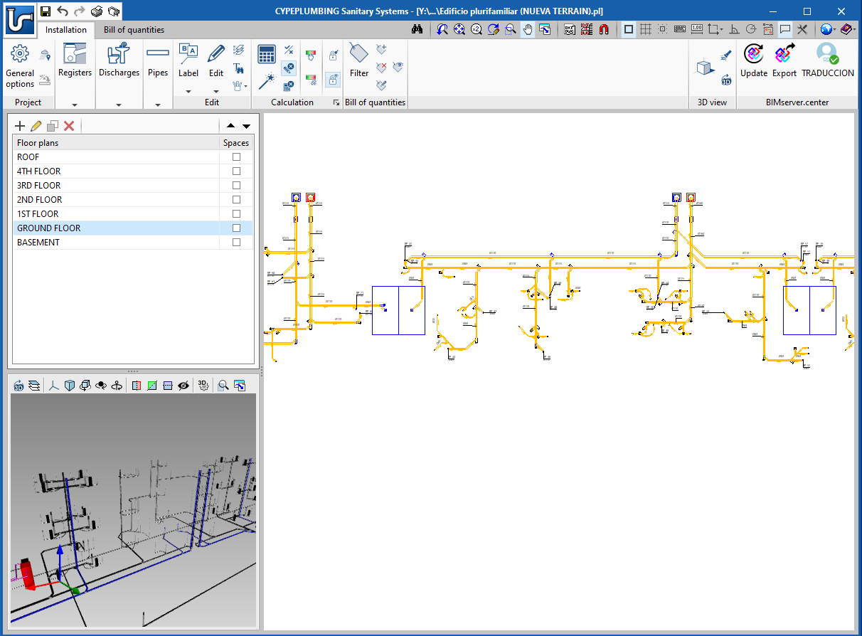
Bill of quantities tab
The "Bill of quantities" tab has been included. Now, users have tools to generate and manage the bill of quantities of the elements that have been entered.
More information in the "Bill of quantities tab" in project phase Open BIM applications.
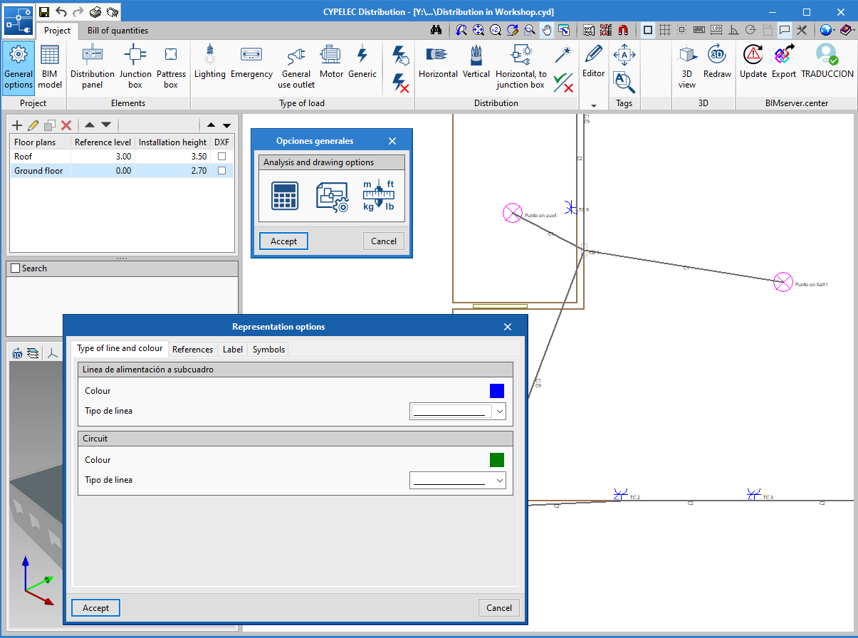
Configure "General options" by design code
Until now, only predetermined configurations were available for infrastructure elements and checks. Now, the program has complete configurations so users may define the "General options" of the project. For each design code, the program has a configuration in which the type of equipment, view preferences, checks, tables, units, etc. can be found, saving users a lot of time when preparing the project.

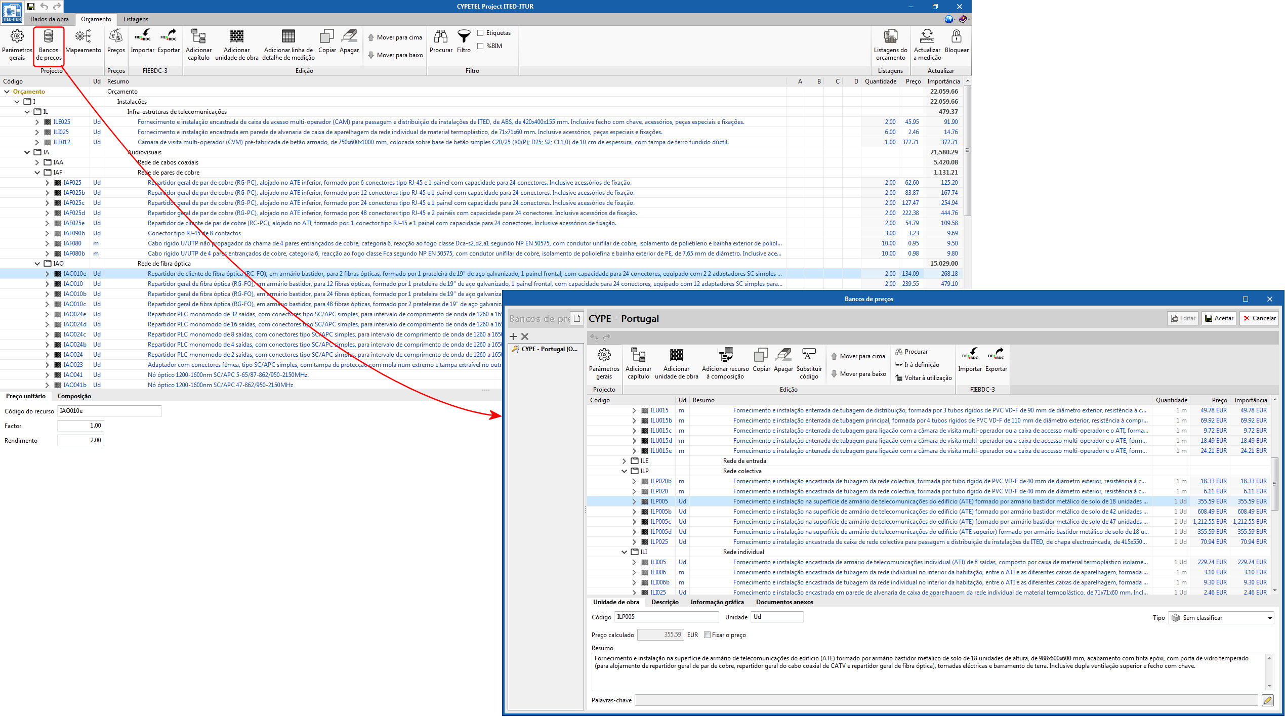
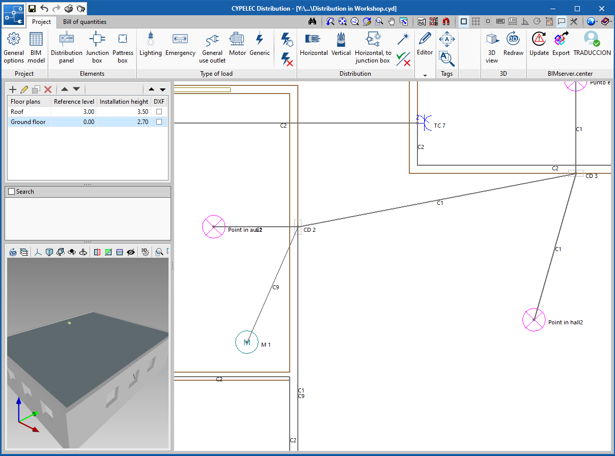
Specific coaxial connectors for S/MATV and CATV
To distinguish between coaxial networks, two connectors have been added: "Coaxial S/MATV" and "Coaxial CATV".
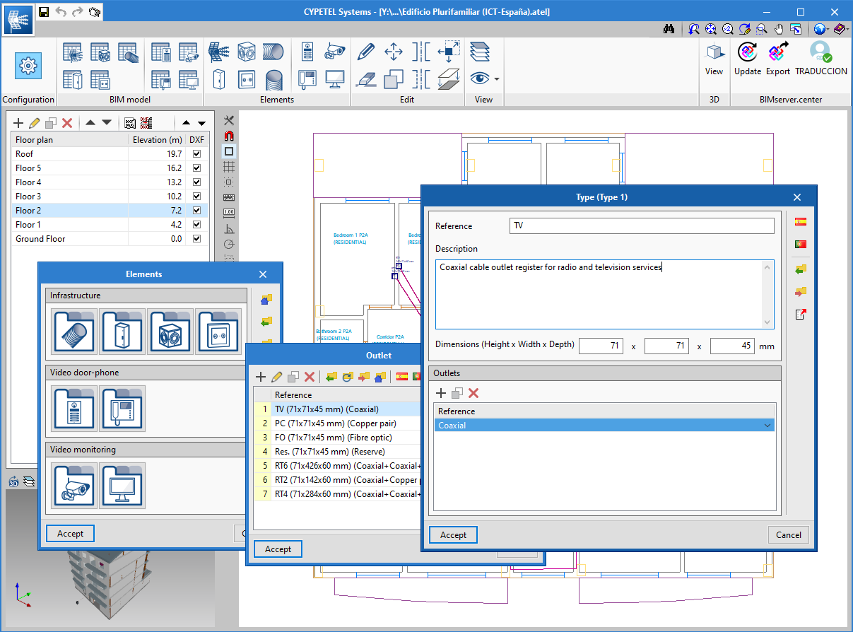
Representation options
New functionalities have been added to represent the types of lines and tags in spans and elements.
The "Representation options" icon has been added in "General options", which includes four tabs:
- Type of line and colour (new functionality). Allows users to select the colour and type of line to represent the supply lines to the subpanel and indoor circuits.
- References. Allows users to assign the default reference for the different elements.
- Tag (new functionality). Allows users to select, for each element, the properties that are to be represented on-screen and later on the floor plans.
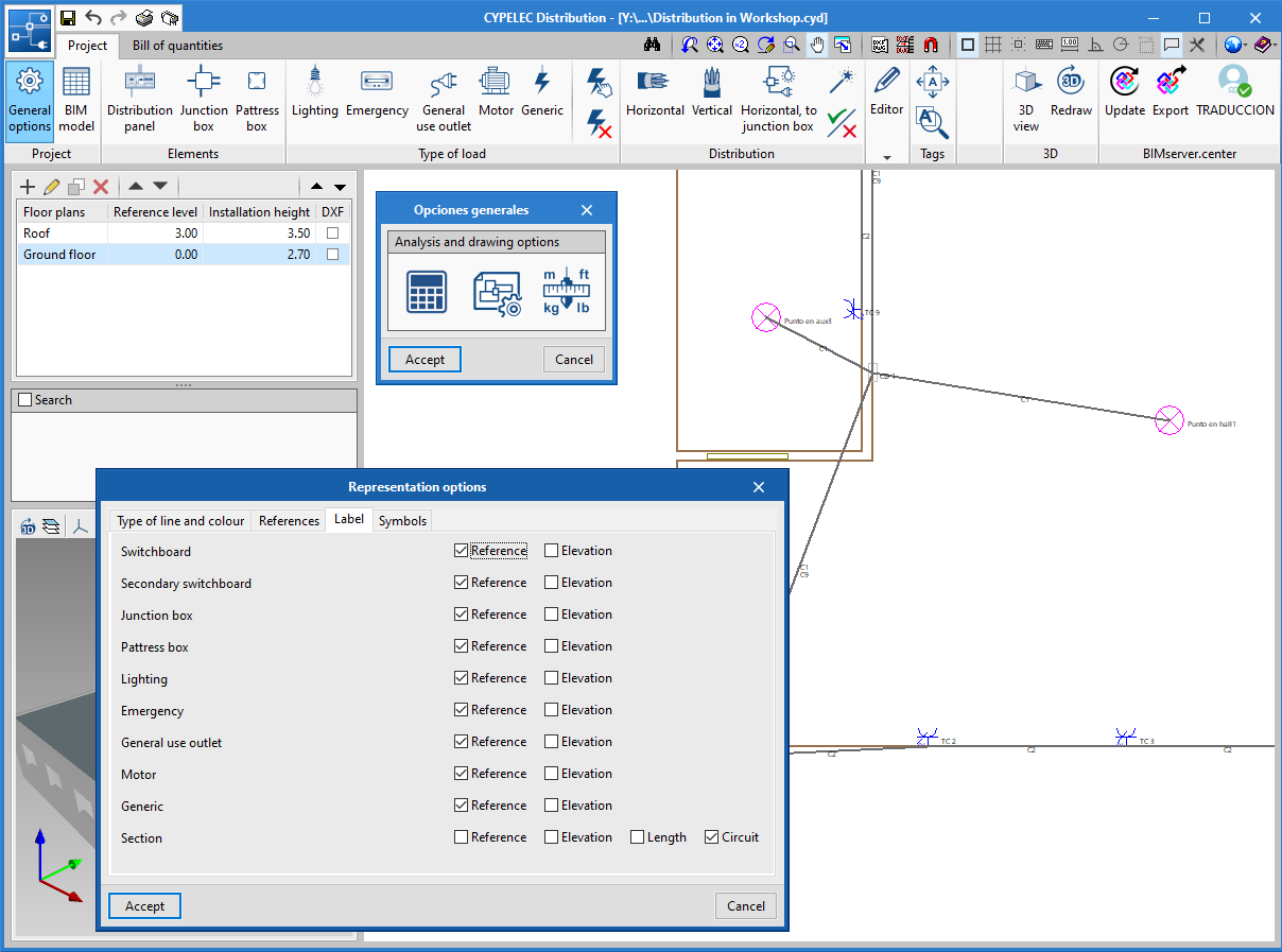
- Symbols. Allows users to edit customised symbols, which can then be assigned to different elements.
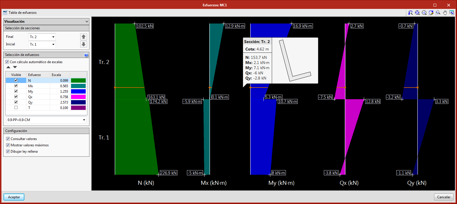
New panel for graphical representation of forces
New panel in which forces are represented graphically. When the "Forces" button is pressed, users access a panel that displays the combination force envelopes of the selected wall.
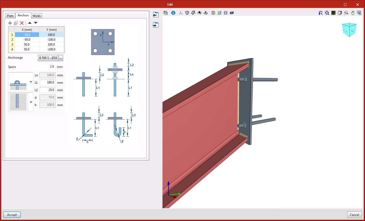
New types of connections
- Anchorage plate to vertical surface
This connection is applicable to I-sections or rectangular hollow sections. A vertically-oriented anchorage plate is generated at the selected end.
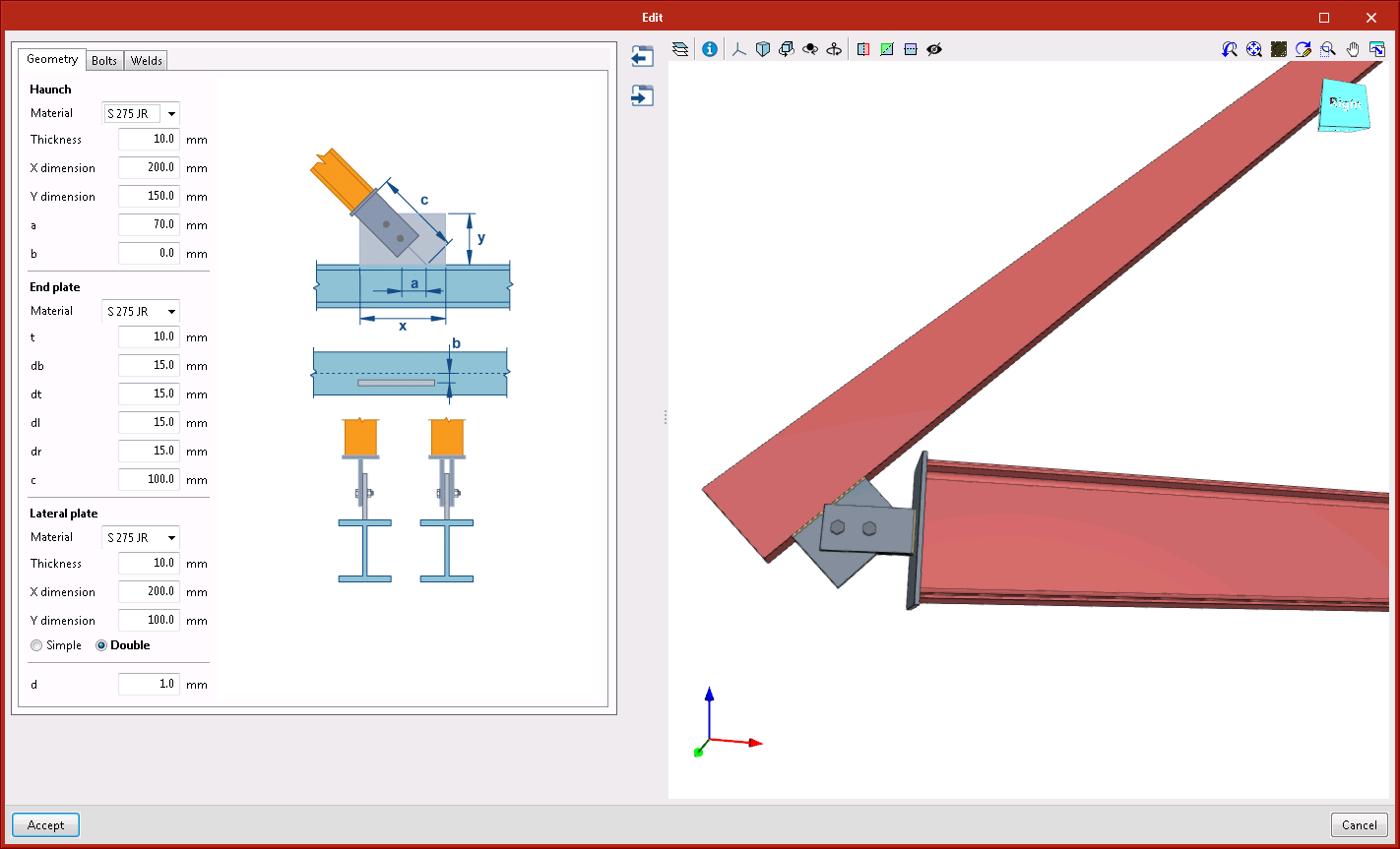
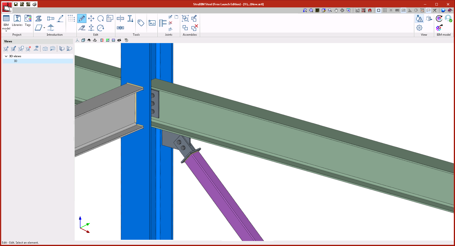
- Moment connection with reduced beam section
Beam to column moment connection, both with I-sections. With this connection, users can define trims in the flanges of the beam. Flanges are welded with single bevel butt welds, to do so, holes are also generated in the web of the beam, so they can be accessed more easily to perform the welds. The web can be connected using welds or bolted using a lateral plate.
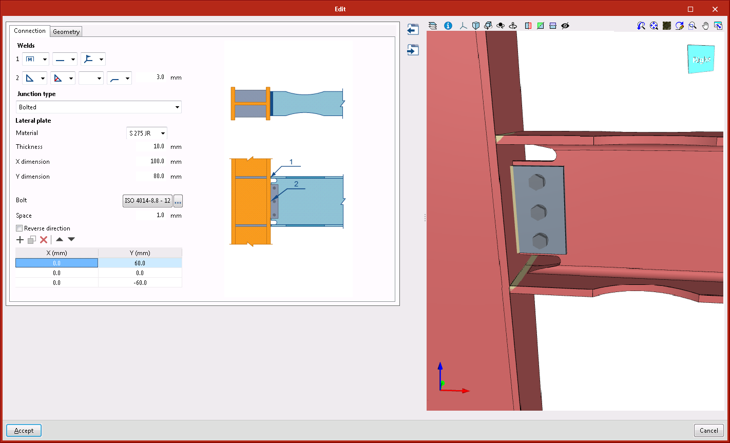
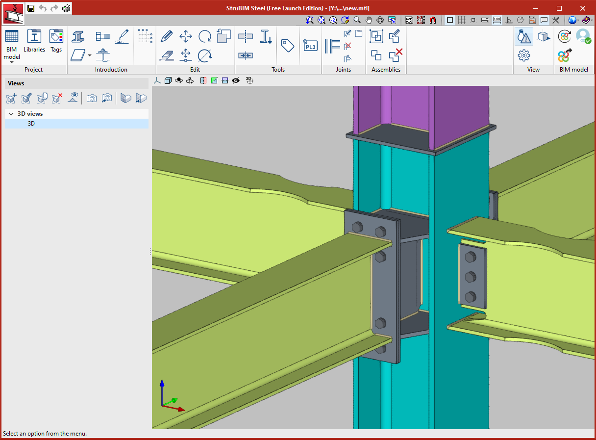
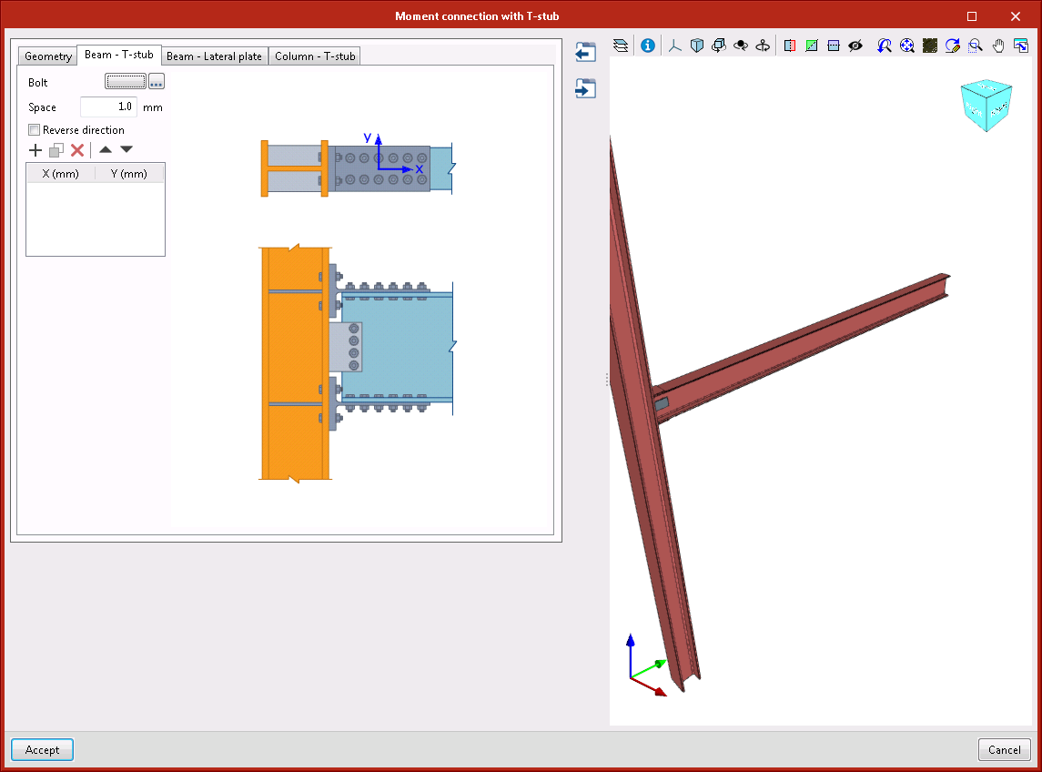
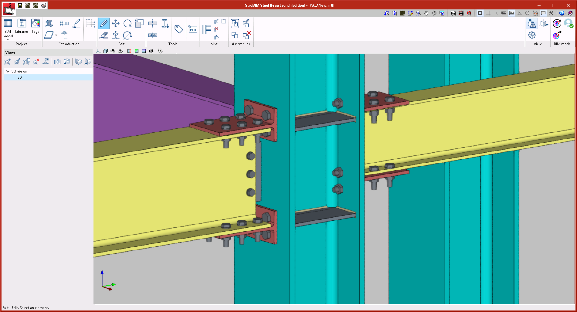
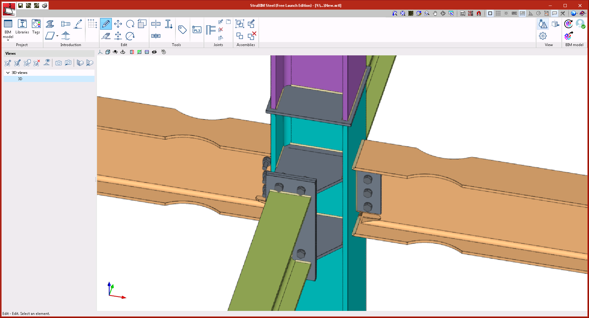
- Moment connection with double T-stub
Beam to column moment connection, both with I-sections. The flanges of the beam are connected to the column using bolted rolled steel T-stubs. The web of the beam is connected using a bolted lateral plate.
- Diagonal connected to the main section, with end plate
This connection can be applied to a main bar consisting of an I-section, basic U-section, rectangular hollow section, or a diagonal bar consisting of an I-section, rectangular hollow section or circular hollow section.
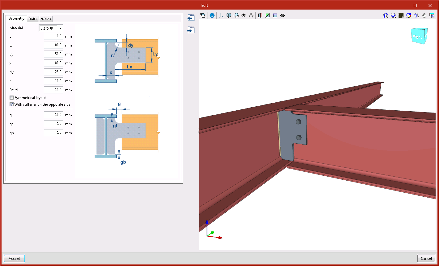
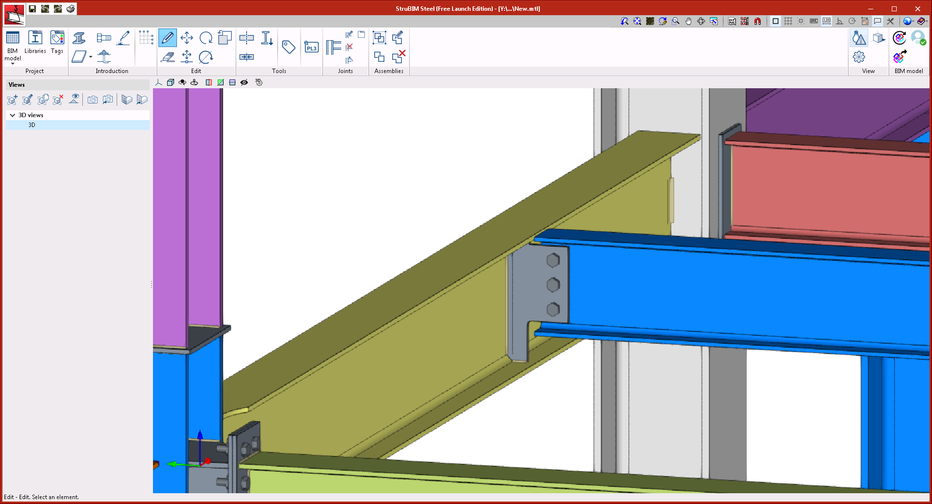
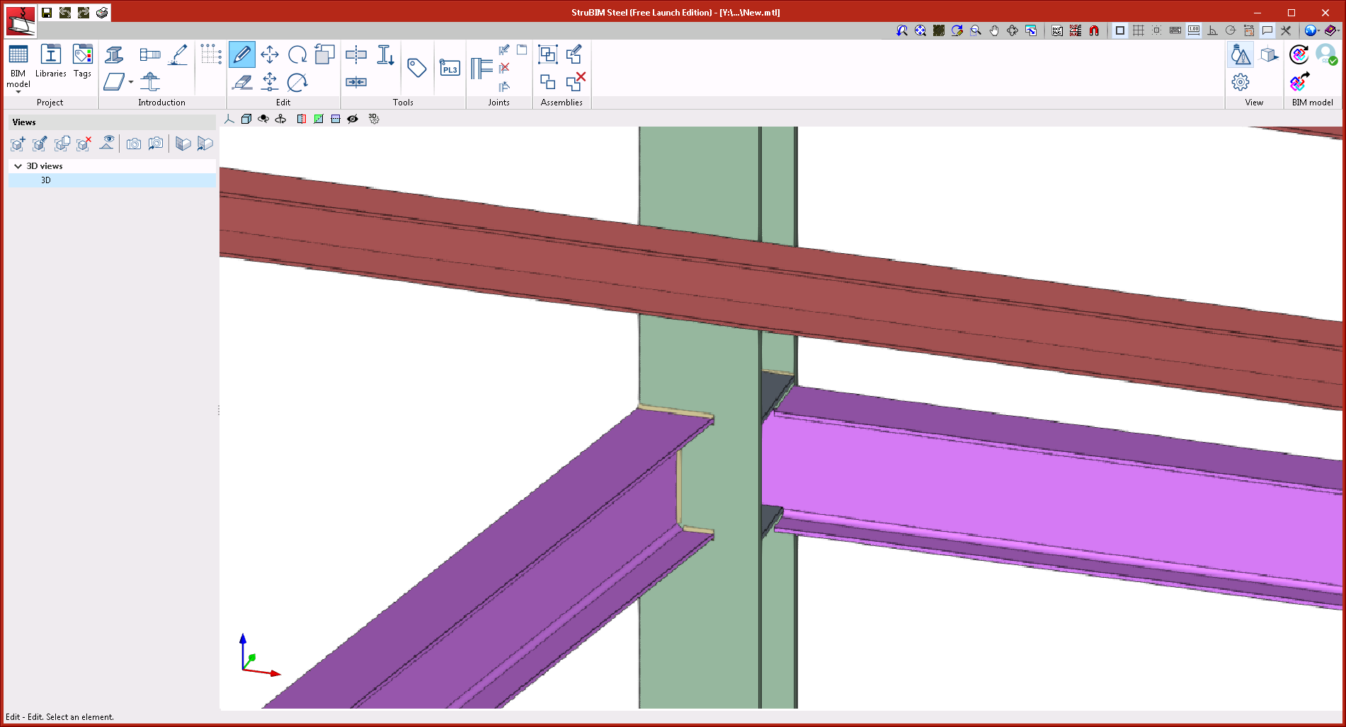
- Beam connected to the web stiffener of the main section
This connection can be applied to a main I-section beam or secondary I-section beam. The secondary beam does not have to reach the main beam perpendicularly. Users can also add a stiffener on the opposite side.
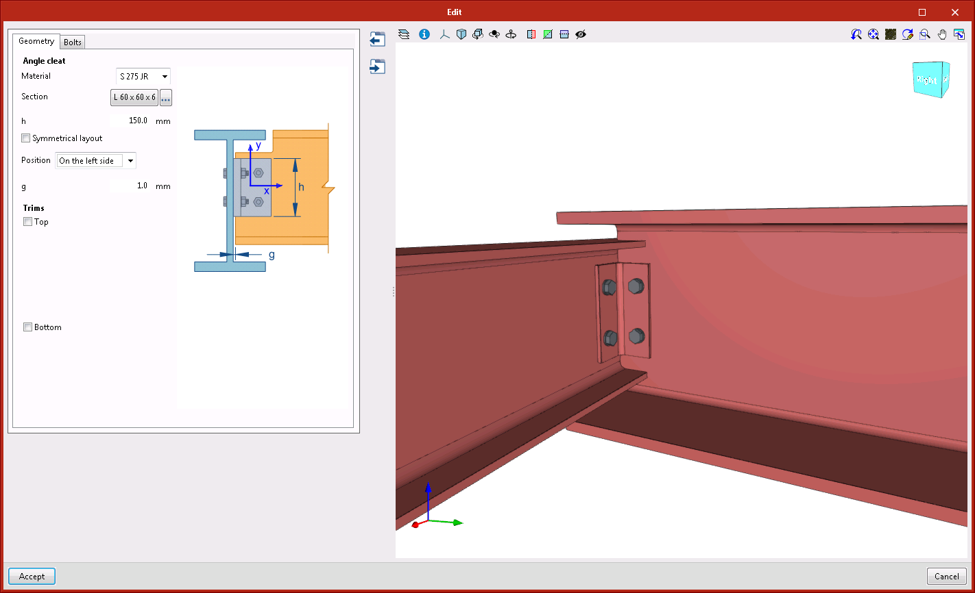
- Beam connected with angle flange cleats to the web of the main beam
This connection can be applied to a main beam or secondary beam with I-sections or U-sections. The secondary beam must be perpendicular to the main beam since the connection is carried out using angle flange cleats with a length that is defined by users.
Improvements in existing connections
The following joints: "Moment connection to the flange of the main section" and "Moment connection to the web of the main section" have been improved. As of the 2021.b version, the webs can be displaced and the beams can reach the column obliquely in the horizontal plane.
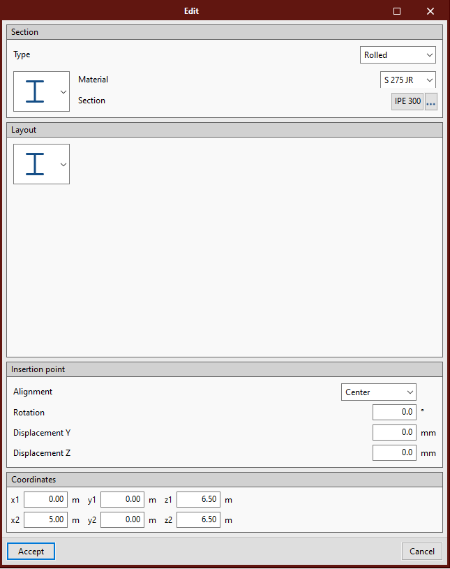
Edit section coordinates
The "Coordinates" section has been added in the edit sections dialogue box where users can consult and edit the coordinates of the initial and end points of the sections.
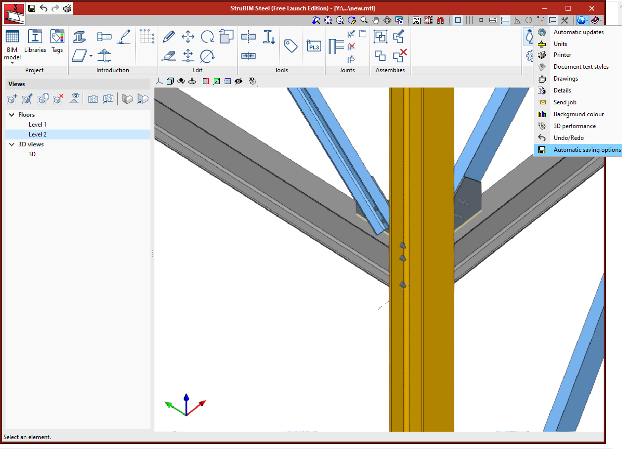
Automatic saving options
Within the "Configuration" menu, "Automatic saving options" has been added. Using these options, users can configure when the work will be saved automatically.
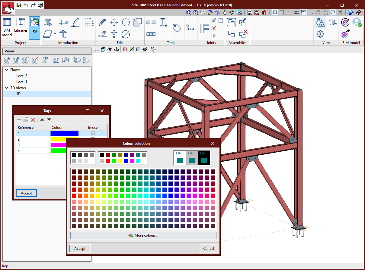
Assign colours by tag
Within the tags manager, each tag now has an associated colour. Elements will be represented in the 3D view, in the colour of the assigned tag. When an element has several tags assigned to it, it is represented in the colour that has been assigned to the first tag, in accordance with the order that has been established in the tags manager.
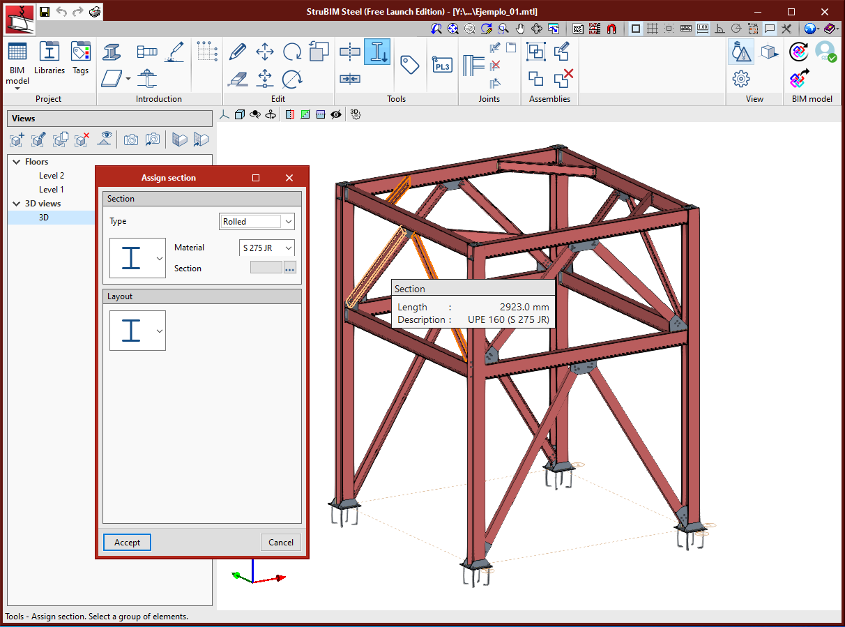
Assign section
A tool has been implemented to assign the type of section to a selection of bars.
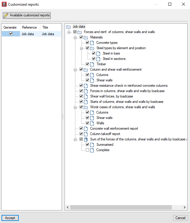
Customised reports
As of the 2021.b version, users can customise CYPECAD reports.
The "Customised reports" option allows users to select the reports that are to be generated. These reports must have been defined previously using the "Available customised reports" button.
These reports can be used in any project and can be used on another computer on which the 2021.b or later version is installed.
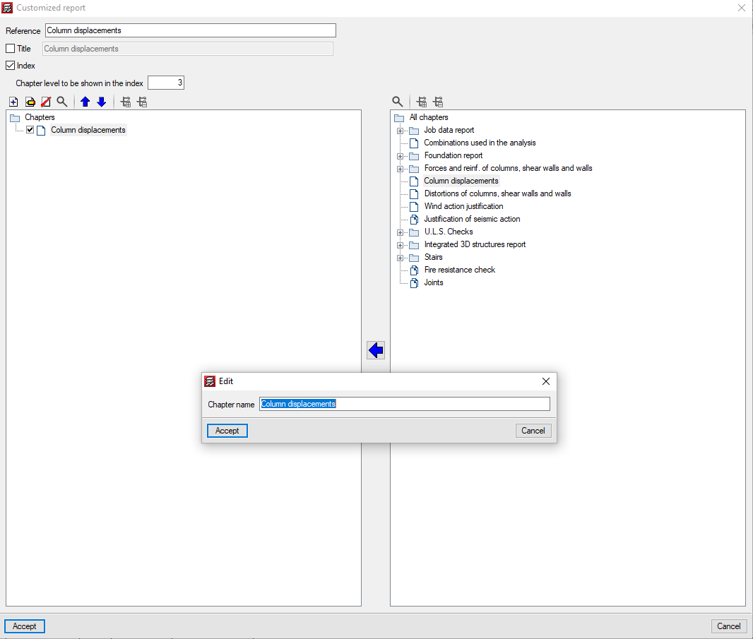
For customised reports, users can define their chapters as well as the title of the reports and whether their index and chapter levels are to appear.
The chapters that make up the report must be selected based on the chapters of the predefined reports that appear in the tree on the right. They can be grouped and organised as users wish. The name of the chapters can be modified, and users can add empty chapters to include the information later on.
For the time being, the chapters of 13 predefined reports can be used, but we continue to work to implement as many predefined reports as possible.
Project reports
In the 2021.b version, the "Reports" dialogue of the "File" menu can be configured by users. The appearance of the panel that is displayed when "Reports" is pressed has changed. It shows all the reports that are available in the program. The buttons that correspond to reports that cannot be displayed in the current project are disabled.
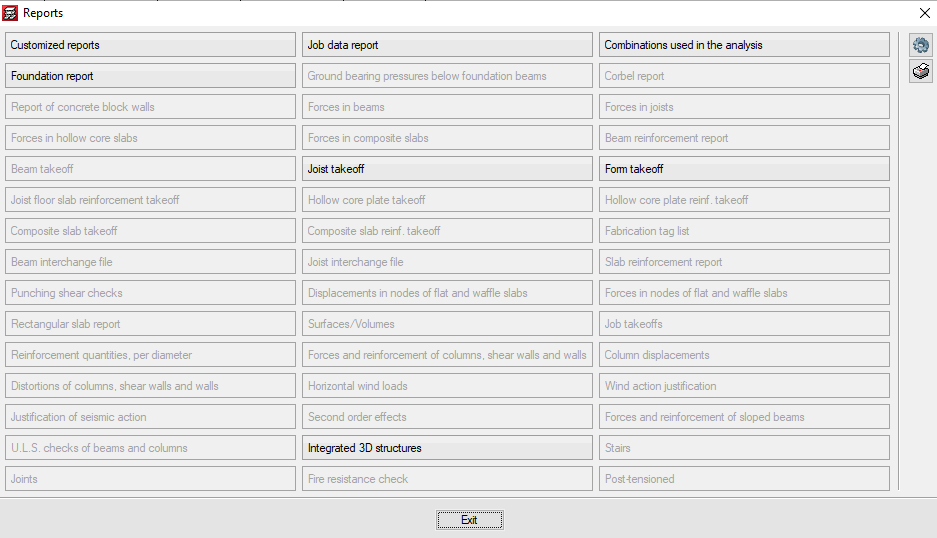
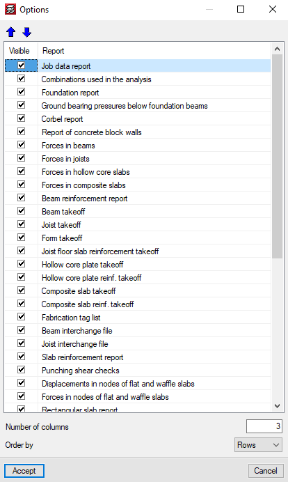
The "Options" button allows users to select which reports appear in the panel and the order in which they are displayed. This way, users can only show the reports that they usually use in the panel organised in accordance to their preference criteria.
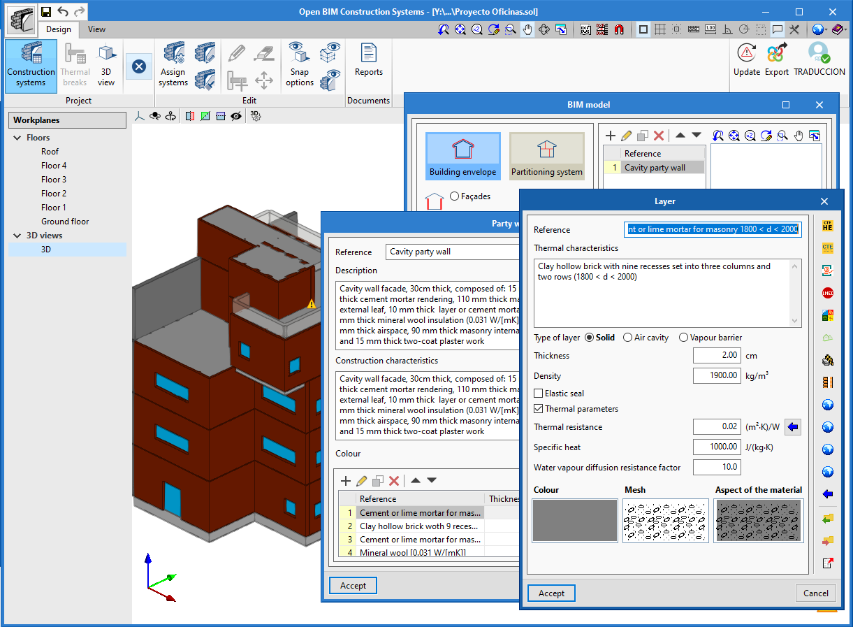
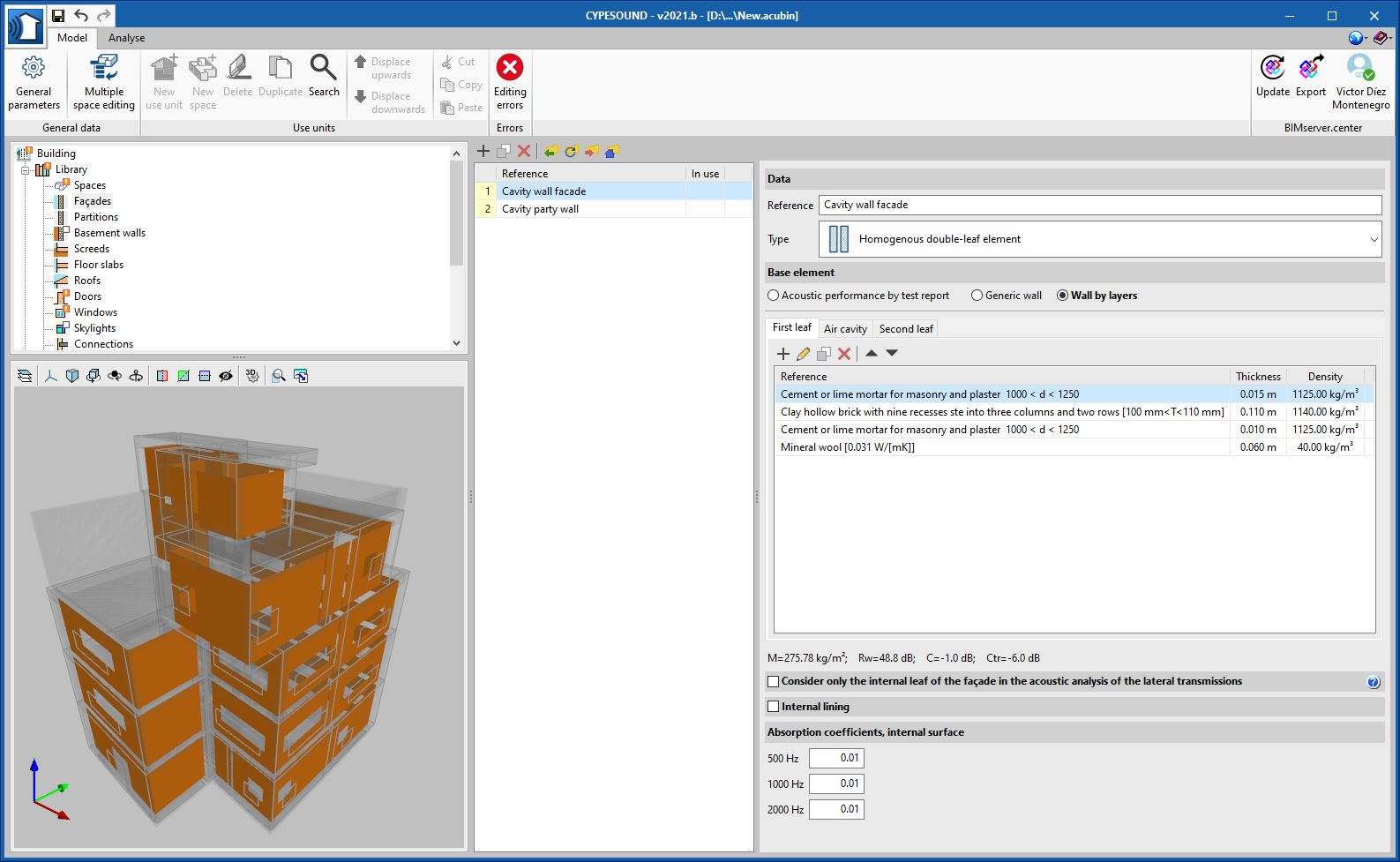
Export the definition of the construction solutions for thermal and sound analysis applications
As of the 2021.b version, CYPE Construction Systems exports the definition of the construction solutions, together with their link to the elements of the architectural BIM model, to the BIMserver.center project. This information can be interpreted by the different specialist BIM tools aimed at the thermal and acoustic analysis of the building.
In the event that there is an association of construction solutions in the BIM project, which has been carried out using CYPE Construction Systems, it will be used for the library of thermal or acoustic simulation programs instead of the types defined in the physical or analytical model. It should be noted that the layers that make up the system and their physical properties will be read, but they will not be modified when the BIM project is updated. This way, user changes are maintained within the specialist application, as well as the types that may be stored in ".bibgen" files.
Below are the current applications that are capable of reading and incorporating the construction systems of CYPE Construction Systems in their design model:
- Thermal simulation
- CYPETHERM HE Plus
- CYPETHERM EPlus
- CYPETHERM LOADS
- CYPETHERM RT2012
- CYPETHERM RT2012 CNOA
- CYPETHERM REH
- CYPETHERM RECS Plus
- CYPETHERM C.E.
- CYPETHERM COMETH
- CYPETHERM RTExistant
- Acoustic simulation
- CYPESOUND
- CYPESOUND CTE
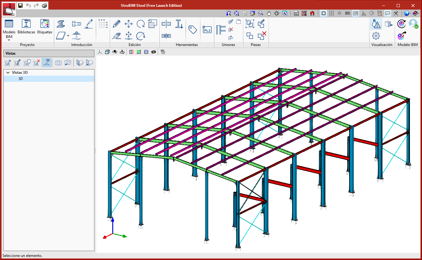
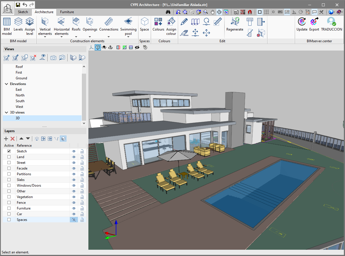
New project example
A new project example has been generated with all the new features of the program. In it, users can view spaces, tags, levels and the new building model painted with colours. We recommend users to open this new project if they wish to inspect the new features of the program.
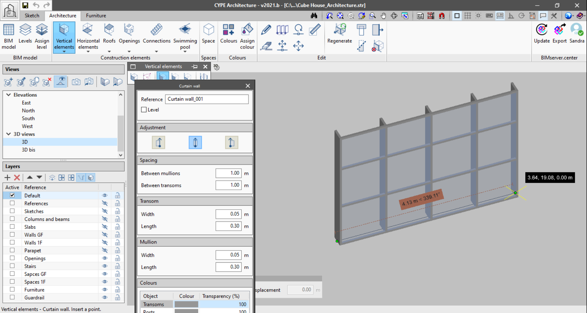
Improved "Curtain wall" functionality
The "Curtain wall" functionality now includes:
- Adjustments when drawing the wall
It can be drawn from the middle, right or left. - Generation of the curtain wall as it is developed
The previous version of the curtain wall only generated complete modules. With this version, the curtain wall is generated as users extend the second point. This way, split modules can be generated. - Preview of the curtain wall
Now, the curtain wall displays a preview of the wall with a fixed height of three modules, to allow users to preview the wall while they are entering it in the program.
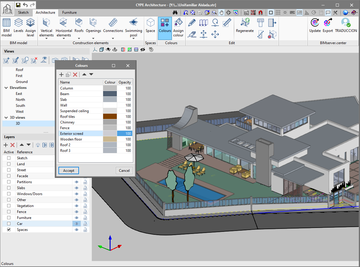
Apply colours to the architectural elements
All the elements of the "Architecture" tab allow users to define colours. There are two ways to define colours for an element.
There are two new buttons, "Colours" and "Assign colour" to define the colour of the more generic elements (walls, floors, columns, beams). The program, by default, creates a list of colours for the elements mentioned above. The default colours can be modified using the "Colours" button. Furthermore, users can create new colours using this button, which can be assigned later on to the elements of the "Architecture" tab.
To assign a colour, simply choose it from the drop-down list in the configuration panel when entering these elements.
To assign the same colour to several elements at the same time, use the "Assign colour" button with which multiple elements can be selected.
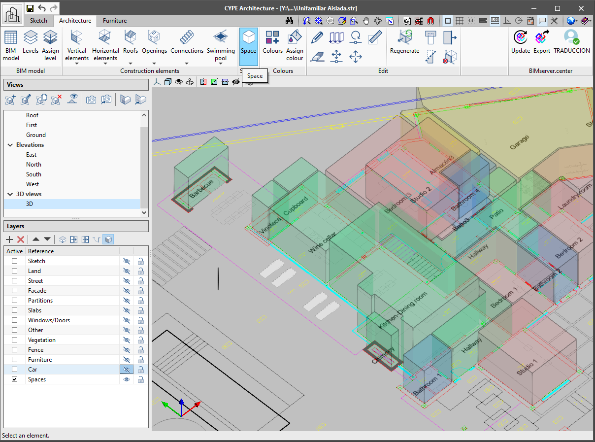
Assign spaces
Spaces allow users to delimit the different rooms of the architectural model. It is essential to define spaces in order to, for example, obtain measurements or perform thermal and acoustic calculations. Additionally, spaces are fundamental reference and representation elements in the Open BIM workflow.
Spaces are defined using a polyline and a height.
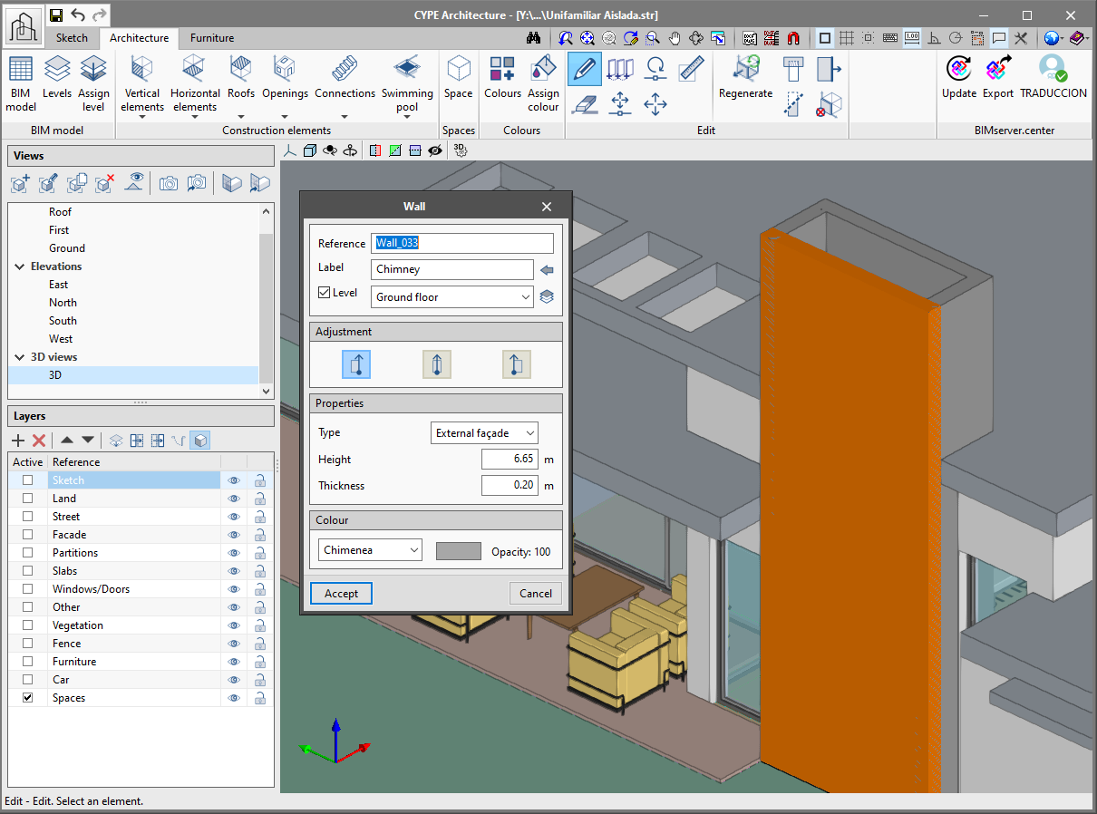
Tag elements
Tags allow users to group elements of the same type. Tags are fundamental for the architectural model to be read correctly in the other applications of the Open BIM workflow.
When elements are entered in our model, they must be assigned a tag, which will then allow users to view them grouped in the other Open BIM programs of the BIMserver.center platform.
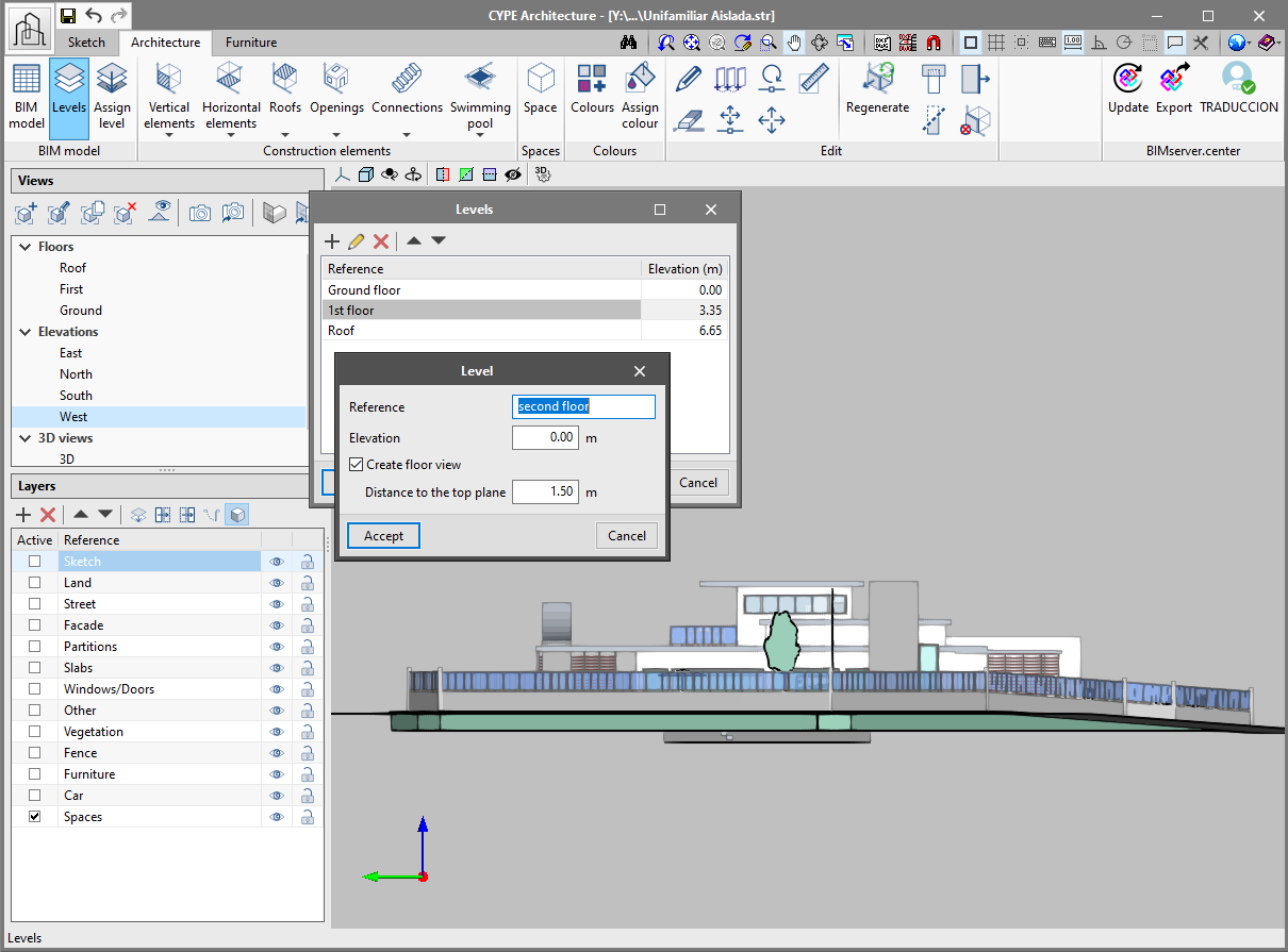
Include levels
The Program, CYPE Architecture, now has levels. The levels allow users to identify the main heights of the building, which are generally, the floor levels. The levels are fundamental for the architectural model to be read correctly in the other applications of the Open BIM workflow.
The levels are created in the "Architecture" tab using the "Levels" button. The main reference levels have to be added in the project using the "+" button. When a new level is created, the program asks if a view of the associated floor is to be created automatically.
A level can also be associated with a plan view from the "Views" panel. It is advisable to associate the levels with the plan views, this way all the elements that are placed in the view are associated directly with the level.
It is recommended to assign the corresponding level to all the elements of the "Architecture" tab.
Installation of CYPE programs
As of the 2021.b version, all CYPE programs are installed using download managers.
Download managers are files with ".exe" format which are downloaded from the "Store" section of the BIMserver.center platform or from the Download area of the CYPE website (depending on which program is to be installed). Each program has its own Download manager.
Using the download managers, users can download and install the chosen program in one of the languages to which the program has been translated, without having to decompress any files with "zip" file decompression software.
Furthermore, with the Download managers, BIMserver.center platform programs can be installed in languages with non-Latin alphabets, such as "CYPE Architecture" or "Open BIM Layout", which can be installed in Chinese.
The Download manager of the complete program package that is installed from the CYPE webpage (http://downloads.en.cype.com/) has been available since the 2014 version. Now, all CYPE programs, including those on the BIMserver.center platform, are installed using Download managers.