The "Updates" option has been implemented in the main CYPE Menu window. Thanks to this tool, multiple updates of installed applications can be carried out via the CYPE Menu.
When clicking on the “Updates” option, a window opens with a list of all installed applications. Select a set of them and, after clicking "Accept", the update process will start.
During this process, progress is displayed in the main CYPE Menu window indicating the current status of the update.
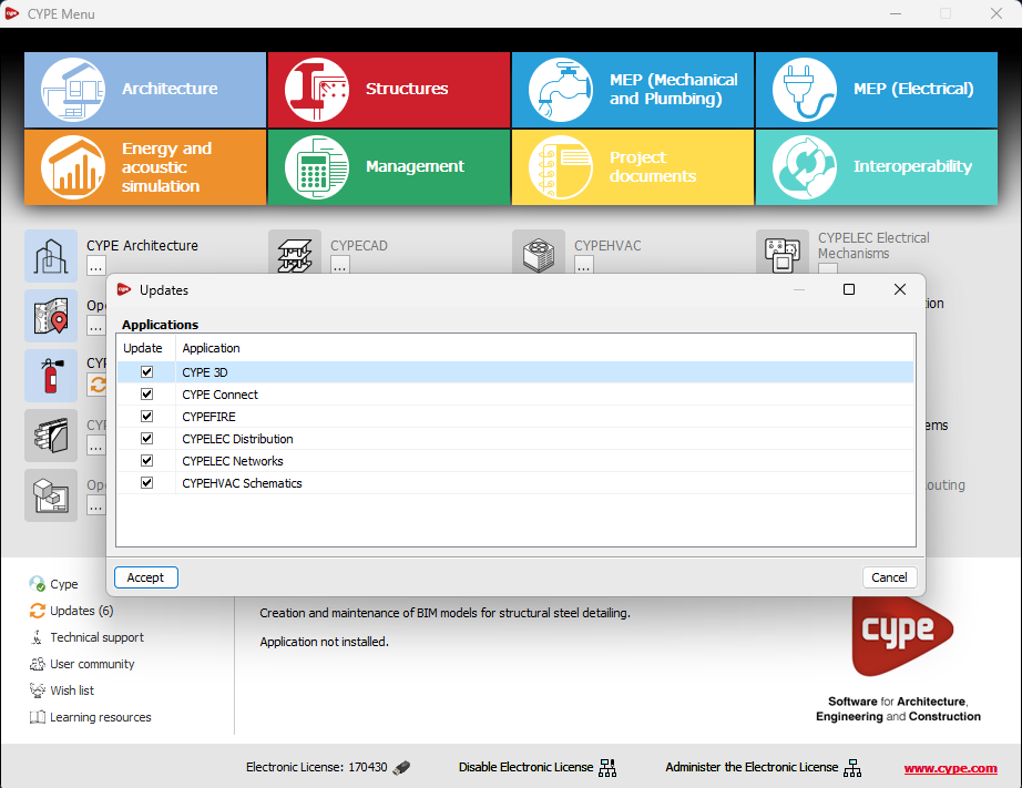
If an update is available for the CYPE Menu itself, it is shown below the list of applications to be updated. However, it is important to note that the update of the CYPE Menu is carried out on its own.
This new feature makes application maintenance easier, ensuring that the latest improvements are always available.
The following modifications have been made to the availability of the applications from the CYPE Menu.
New:
- CYPEHVAC Schematics
- ELODIE by CYPE (Only in the CYPE Menu in French)
Deleted:
- CYPELEC Core, CYPELEC REBT, CYPELEC NF and CYPELEC RETIE. They are joined together in a single program called CYPELEC.
- CYPESOUND CTE, CYPESOUND NRA, CYPESOUND RRAE, CYPESOUND DRAPDE. They are integrated into CYPESOUND.
- CYPEURBAN. Available for download and installation from the BIMserver.center platform.
- IFC Uploader. New contributions can now be created directly from the project page on the BIMserver.center platform.
- CYPEFIRE FDS Viewer. CYPEFIRE FDS can be used to view FDS simulations.
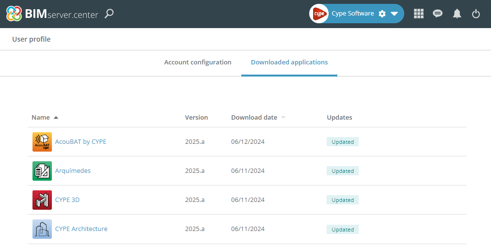
There is now an additional option in the main CYPE Menu window to “Log in” to BIMserver.center.
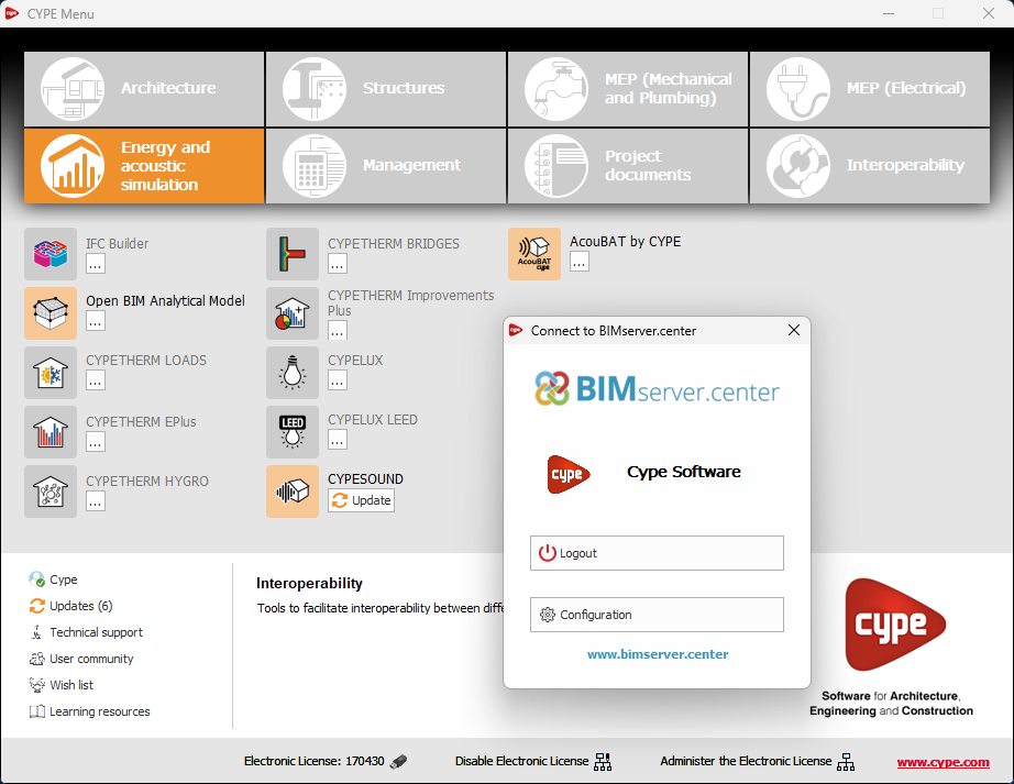
This way, downloaded applications also appear in the user's account on the BIMserver.center platform.
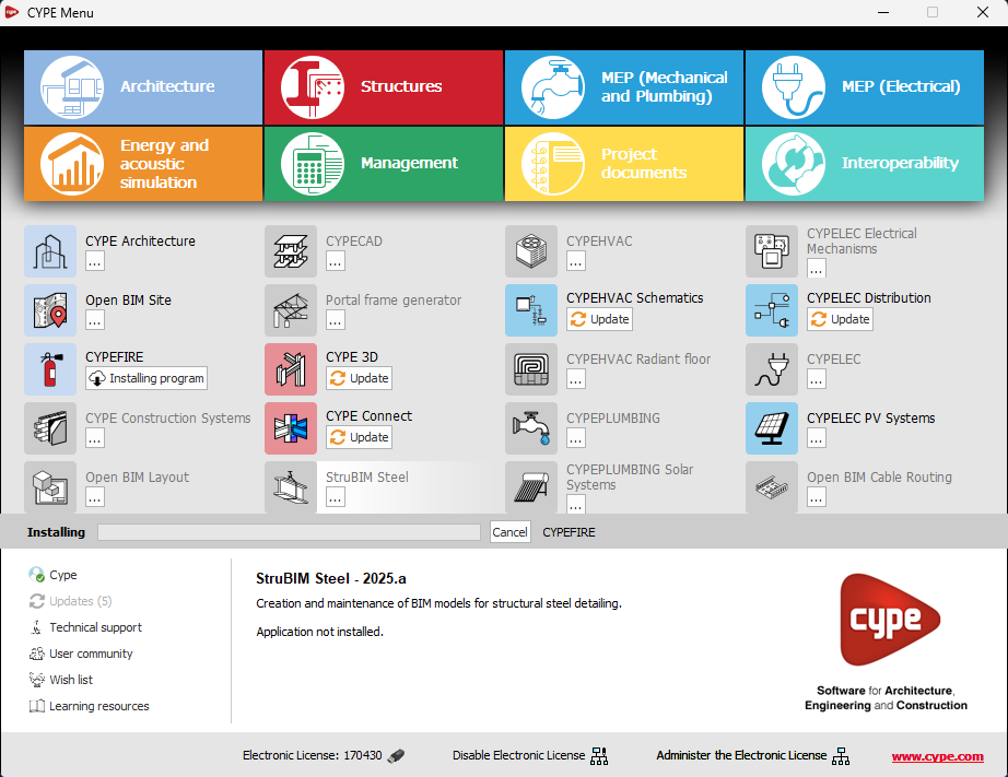
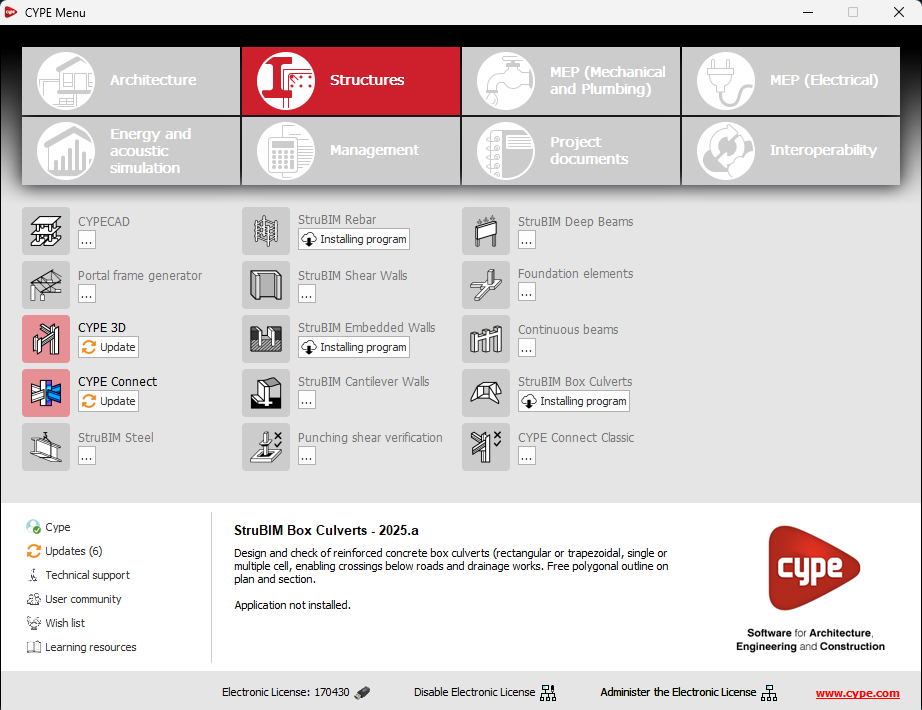
In the new 2025.b version of CYPE Menu, the background installation feature has been added. Users can now continue working on other tasks while applications are automatically installed in the background.
During the background installation process, the “Installing program” message is displayed next to the applications button in the main CYPE Menu window. Once completed, the message disappears and the application can be run.
This feature is designed to make applications easier to use and manage, improving productivity and the overall experience by minimising waiting time and interruptions during the installation of new applications or upgrades.
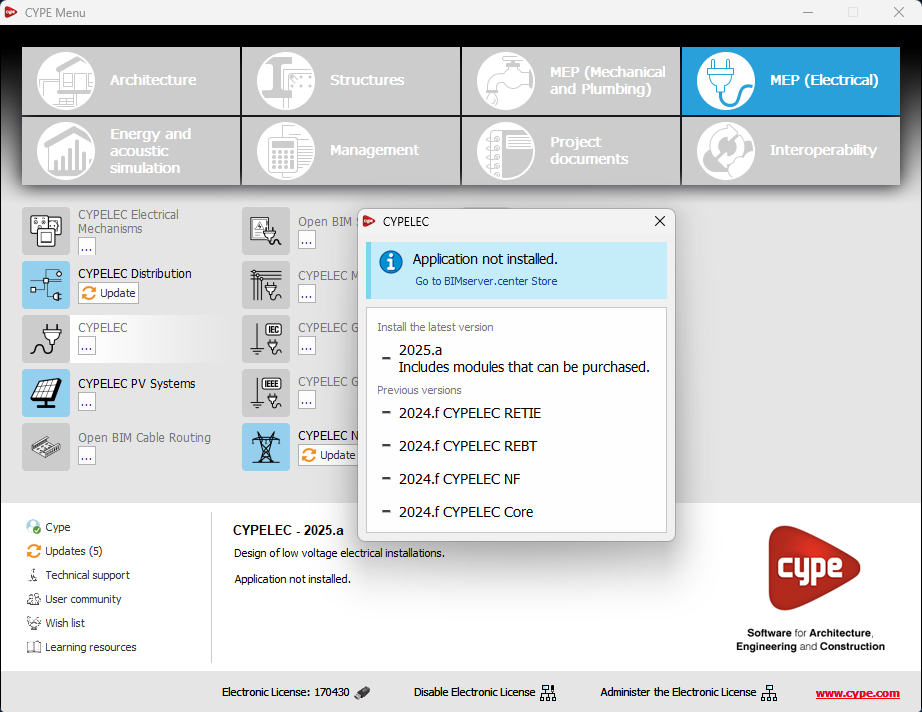
An information message has been incorporated into the installation button of the applications so that, before proceeding with the installation, users can identify which applications are free to use (free of charge) and which require licensing permissions (including paid modules).
This enhancement improves the user experience by providing clarity and transparency on the options available to the user based on their license model.
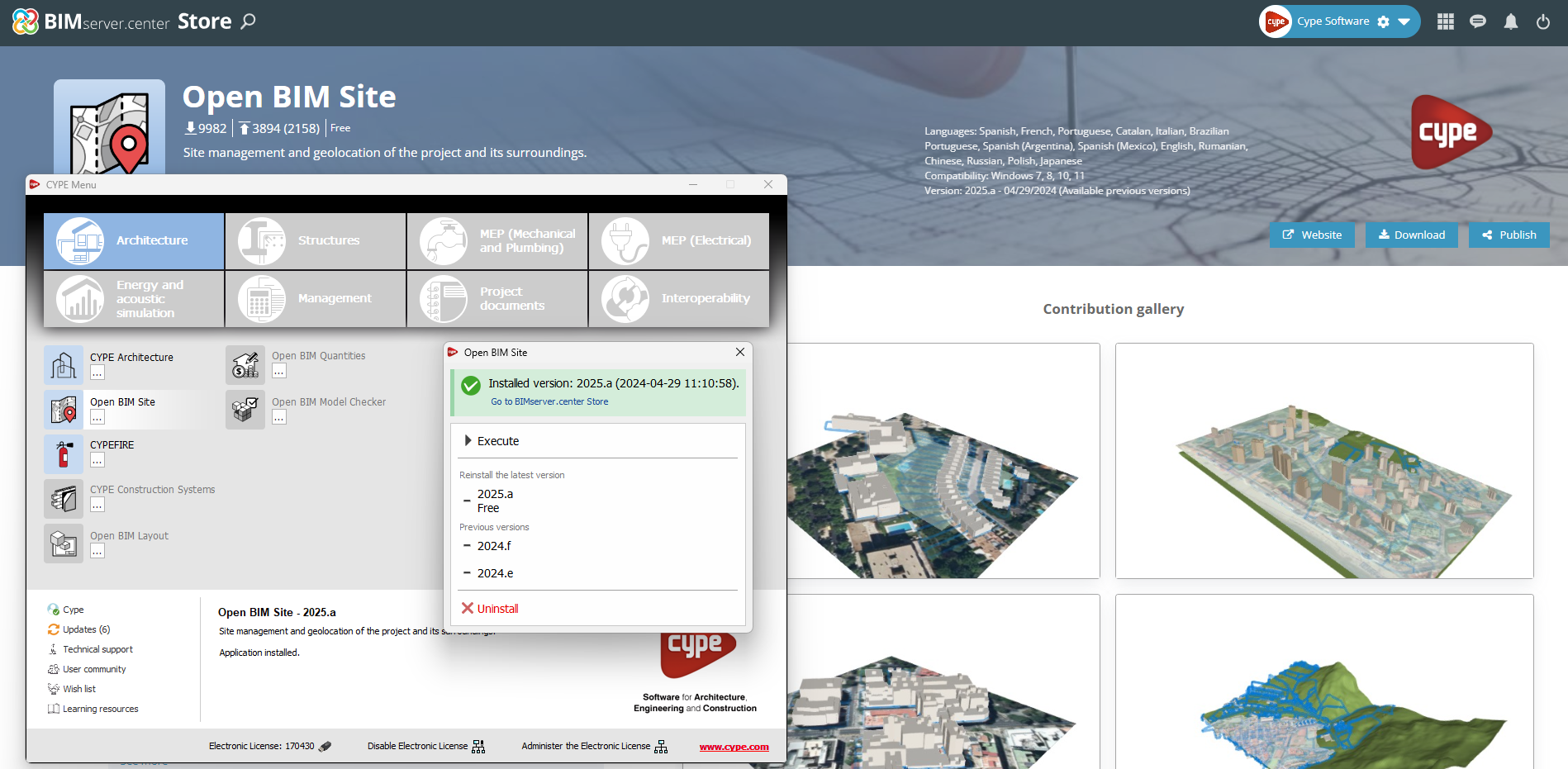
In the configuration panel for each application, a direct link to its page in the BIMserver.center web store has been included.
By clicking on the “Go to BIMserver.center Store” button, users are redirected directly to the corresponding page in the Store, where they can learn more about the application, view its features, read reviews from other users and see examples of real contributions.
This feature provides easy access to additional resources and support, enhancing the user experience by providing quick and easy access to all relevant information about the applications.
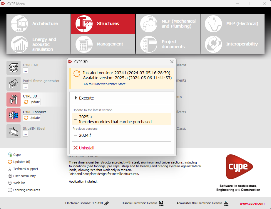
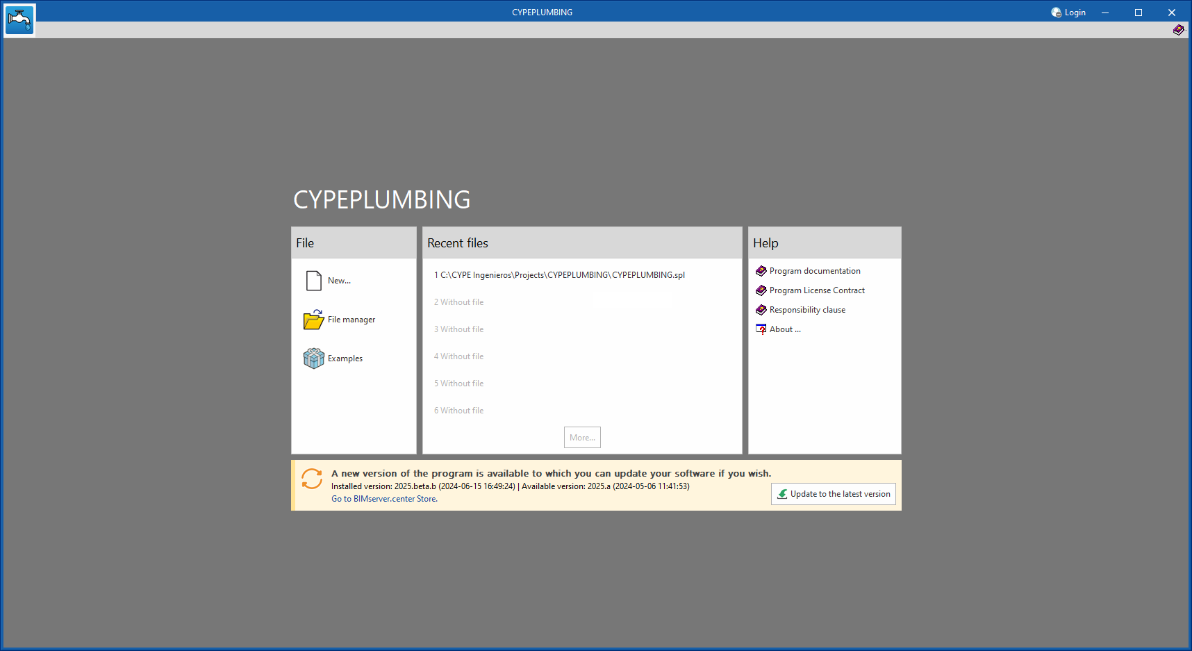
As of version 2025.b, applications now display a warning message in their initial window when a new update is available. This message provides information about the "installed version" and the "available version", together with a direct link to the Store page of the BIMserver.center web platform.
Clicking on the “Upgrade to the latest version” button automatically starts the download and installation process of the application. This feature ensures that the most current version of the program is always being used, thus benefiting from the latest improvements.
This method replaces the automatic notification and update process of a new version in the BIMserver.center programs available in previous versions.
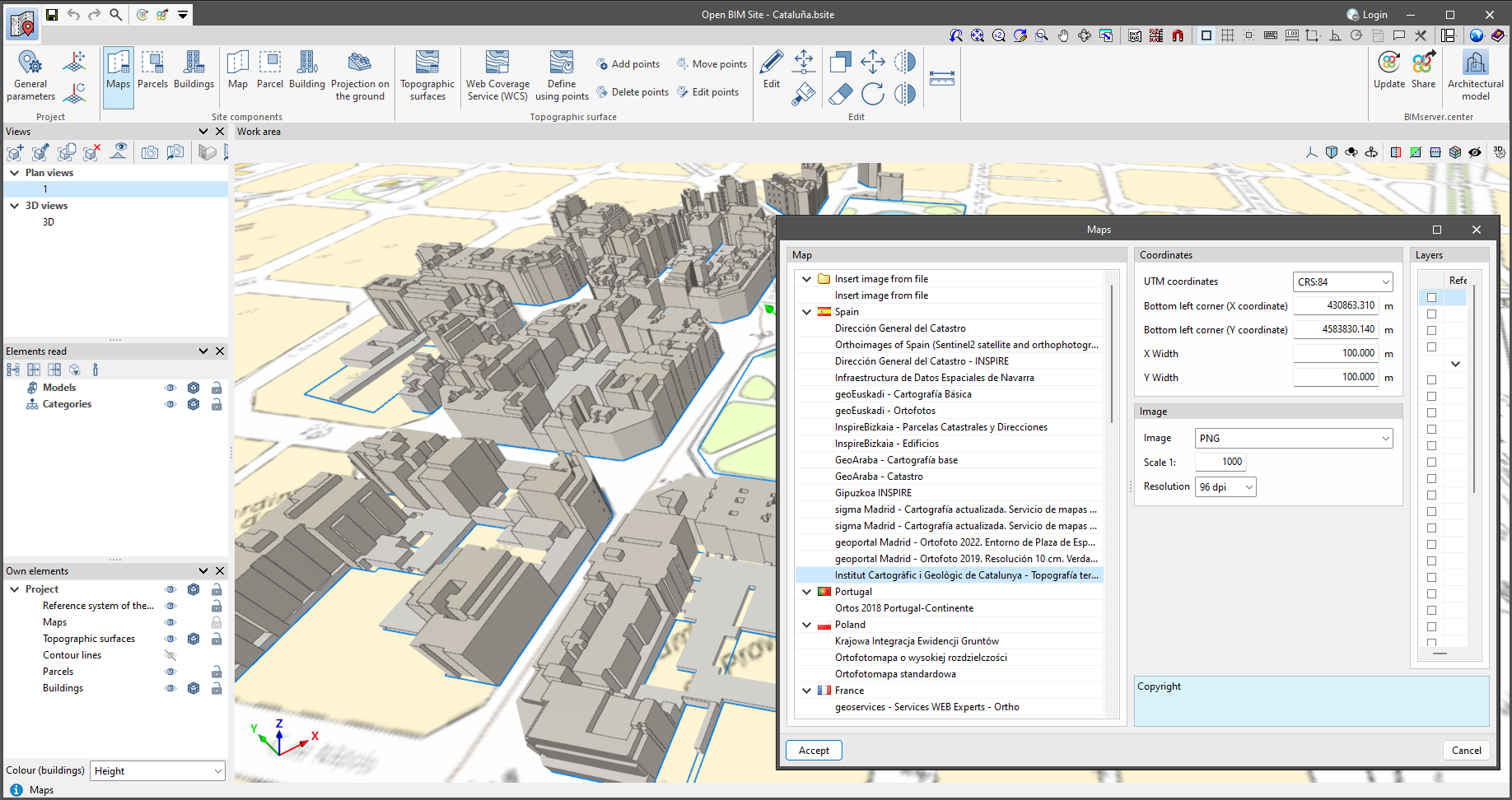
As of version 2025.b, Open BIM Site allows maps to be obtained via WMS services from the following data sources:
- Spain
- Institut Cartogràfic i Geològic de Catalunya - Topografia territorial.
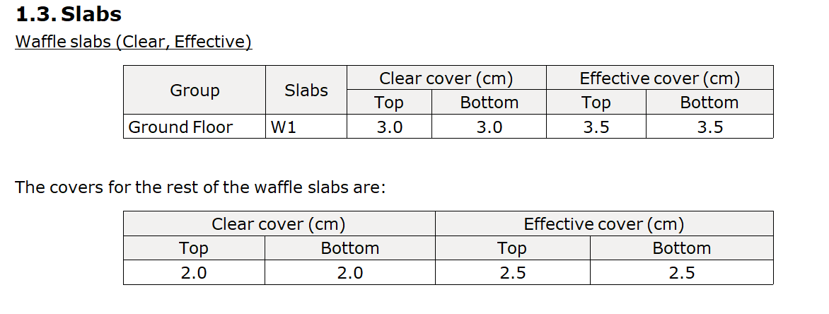
In CYPECAD version 2025.b, the possibility of assigning covers to panels other than those entered in the general data of the job has been implemented.
To do this, in "Beam Definition > Panels > Assign covers" users can select the "Specific for the panel" option.
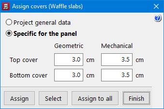
The option has been implemented for all types of floor panels that can have covers: waffle slabs, flat slabs, joist floor slabs, composite slabs and hollow core slabs.
In the job data report, in the "Covers" section, the different covers defined for the panels are shown, if applicable.
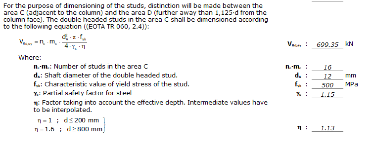
As of CYPECAD version 2025.b, the punching shear check according to the specifications of EOTA TR-060 (European Organisation for Technical Assessment) is implemented for punching shear studs from PEIKKO.
This implementation involves a modification of the checks carried out both on the critical perimeter and on the outer perimeter of the punching shear reinforcement when using bolts from manufacturers with ETA (European Technical Assessment) documents, as is the case with PEIKKO punching shear studs, which optimises their use and their resistance capacity together with the slab.
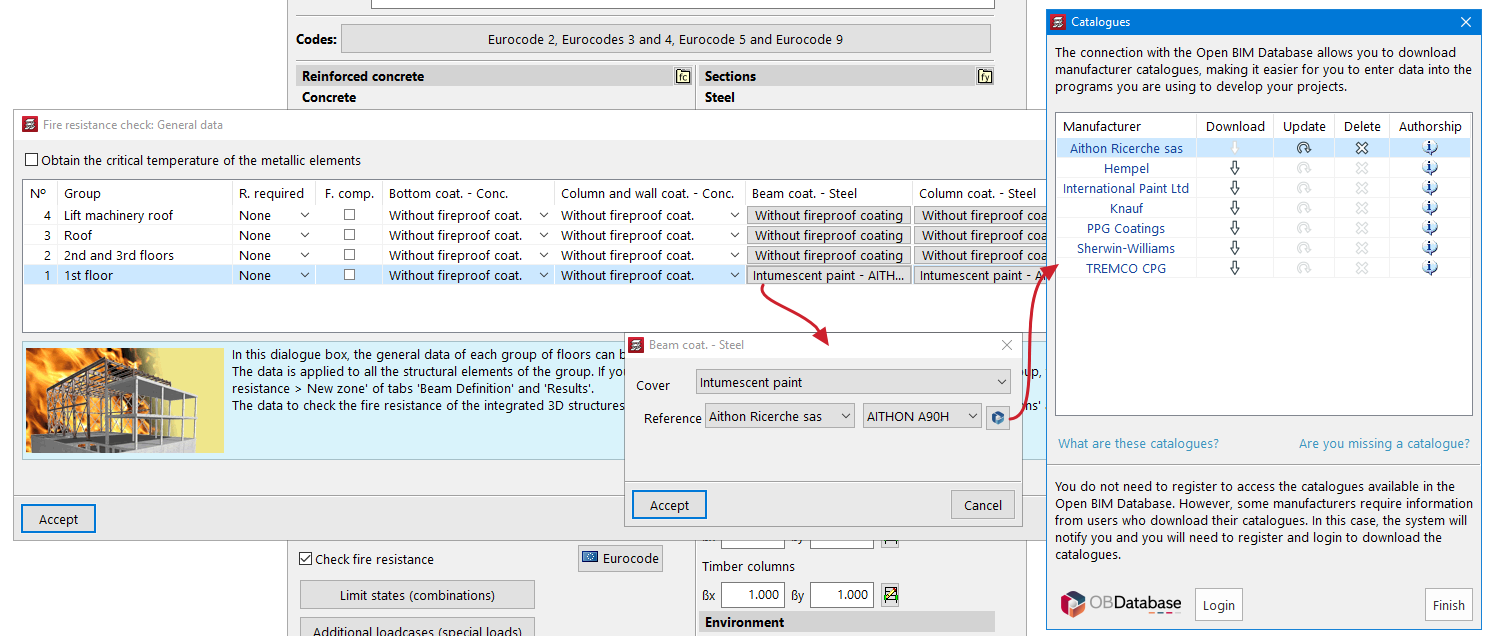
In CYPECAD version 2025.b, intumescent paints from manufacturers' catalogues have been incorporated.
In "Job > General data > Check fire resistance", users can select the type of protective coating for the steel beams and columns on the individual floors of the job. By selecting "Intumescent paint", the available catalogues can be used.
The thickness of intumescent paint required to protect each of the steel elements is obtained from the selected catalogue, based on the calculated critical temperature, the form factor, the number of exposed faces and the type of structural element (column or beam).
The form factor is calculated from the exposed section surface and its area. For columns, the entire surface is considered to be exposed. For beams, their exposed area is obtained by considering the position in the floor slab.
As of version 2025.b, CYPE 3D features a new dockable window system that replaces the main screen user interface. As a result, users can now customise the workspace to suit their needs.
Dockable windows can be moved and resized. They can be either floating windows, pinned to a location within the application's main dialogue box, dragged outside of it, or even moved to another monitor.
More information on Dockable windows can be found in the link to the new feature from version 2023.e.
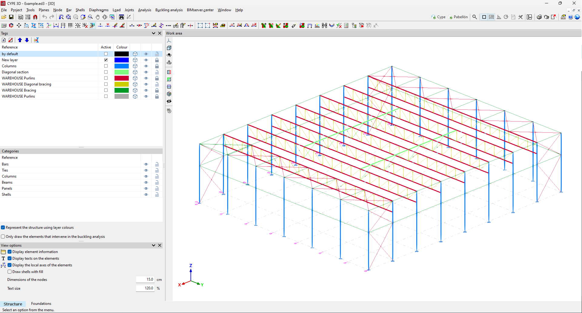
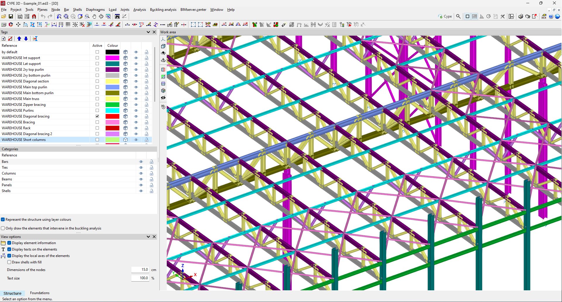
In previous versions, the program had display layers. With the "Layer management" tool, users could create layers and define their configuration, and each element could have one or more layers assigned to it.
As of version 2025.b, this tool is now called "Tags" and will be one of the dockable windows that users can keep on screen (more information on the new CYPE 3D version 2025.b dockable window environment). This window is divided into several sections: the list of tags, the list of categories and other drawing options.
While defining and analysing the model, users often need to show or hide certain elements and enable or disable elements that can be snapped (for deleting, editing, etc.). This implementation gives users direct access to this tool. One of its main advantages is being able to activate/deactivate the display and/or snapping of elements according to tags or categories with a click of the mouse.
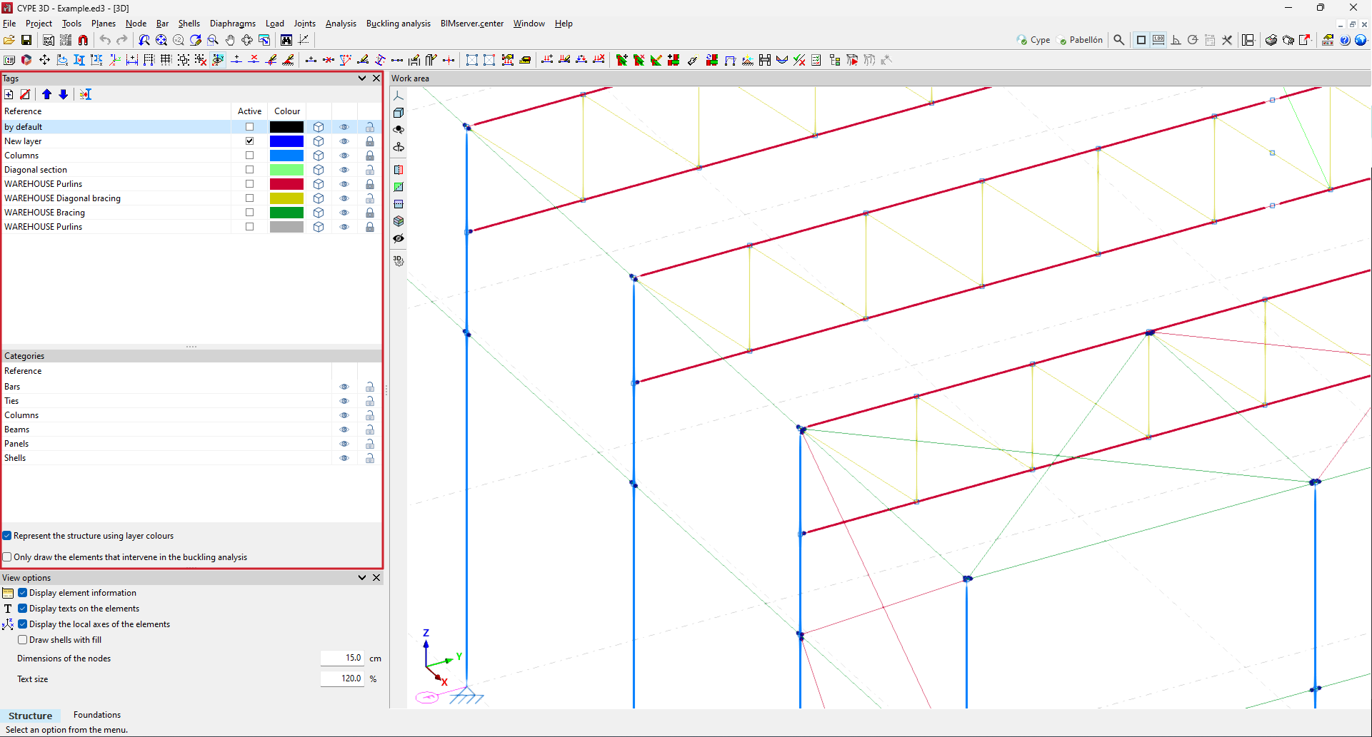
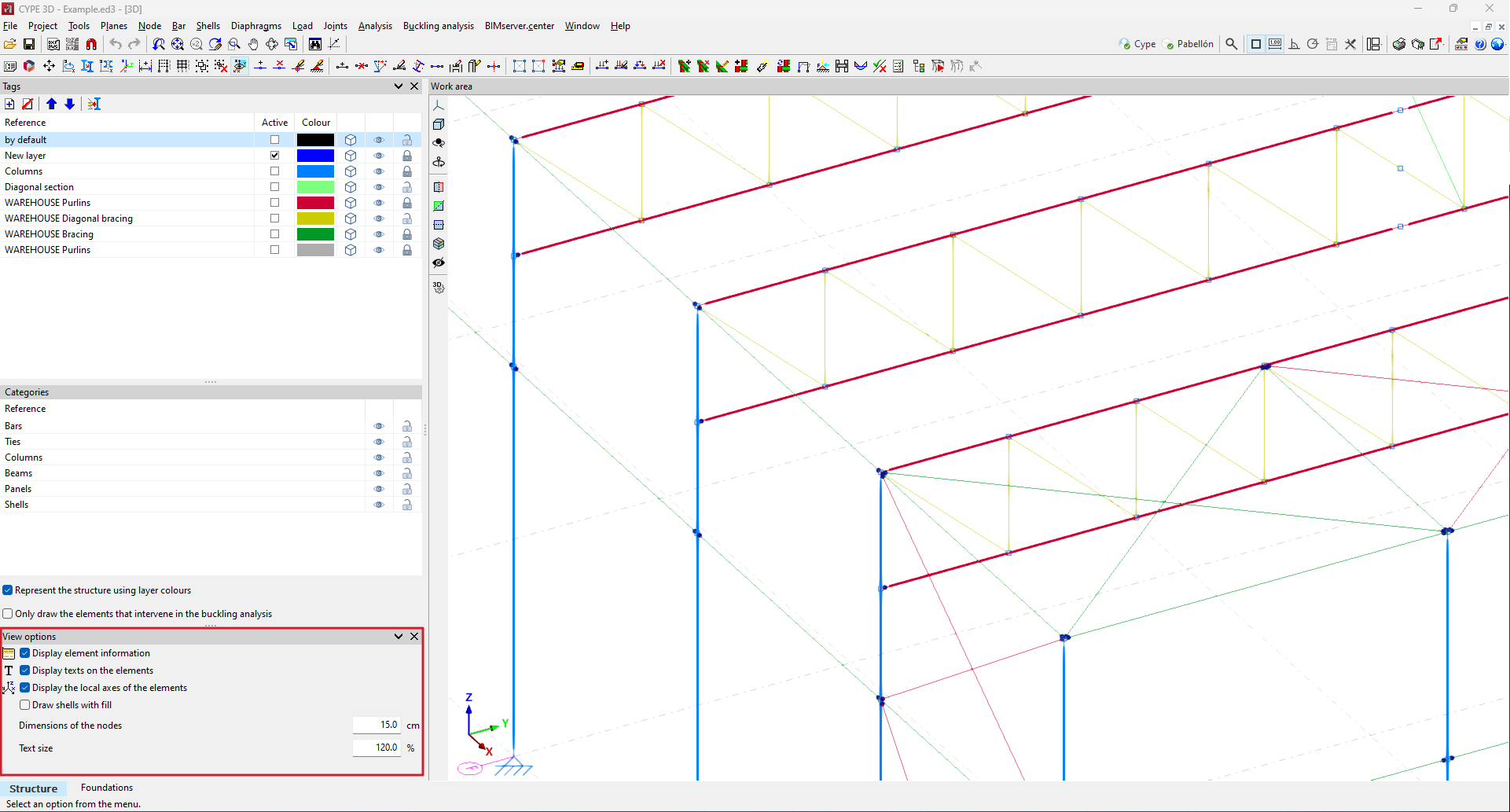
As of version 2025.b, the "Drawing preferences" window, which was located in the "Job" menu, has become a dockable window with the name "Display options".
These options, which are very common when using the program, have been placed within the program's main dialogue box to provide users with direct access to them.
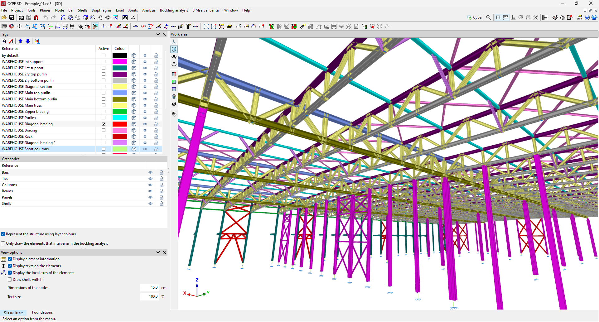
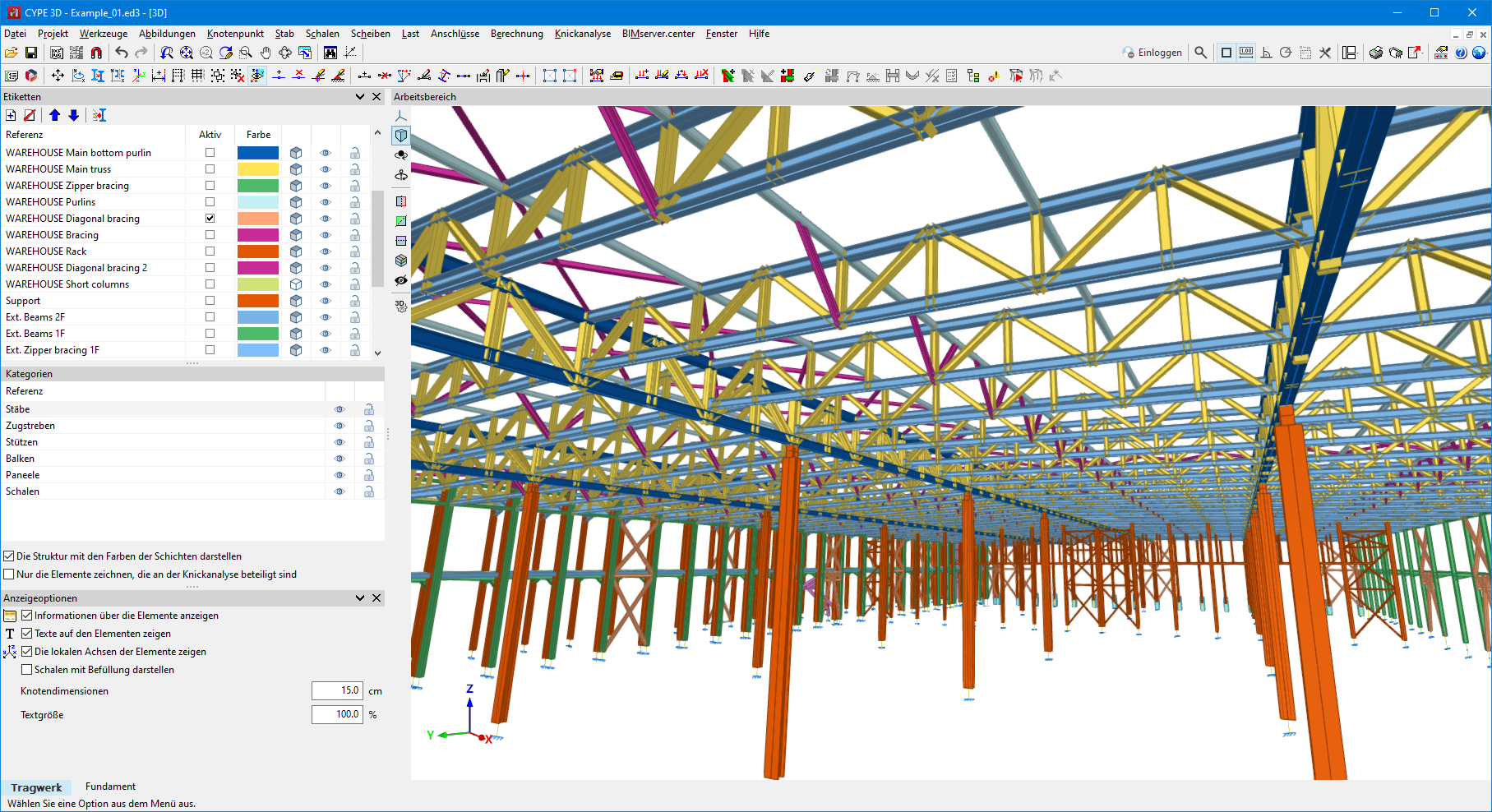
In version 2025.b, the drawing of 3D elements has been implemented.
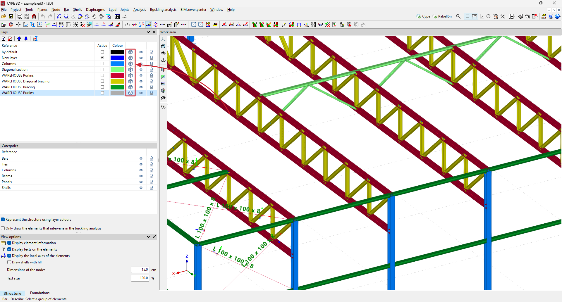
Up until now, bars were drawn schematically as one-dimensional elements and shells as two-dimensional elements.
As of version 2025.b, users can choose how elements are drawn, schematically or in 3D. This selection can be made independently for each tag (in the new "Tags" dockable window from version 2025.b).
When the 3D representation is selected, the bar texts are not represented to improve the display.
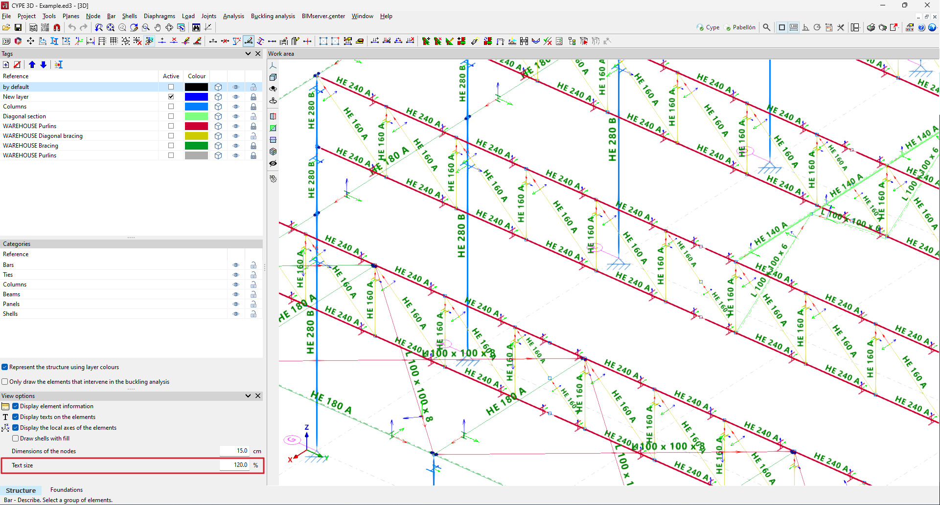
As of version 2025.b, the size of the texts displayed on the screen in the work area can be edited.
The "View options" window includes the "Text size" section, where users can vary the size using a percentage, with 100% being the default size.
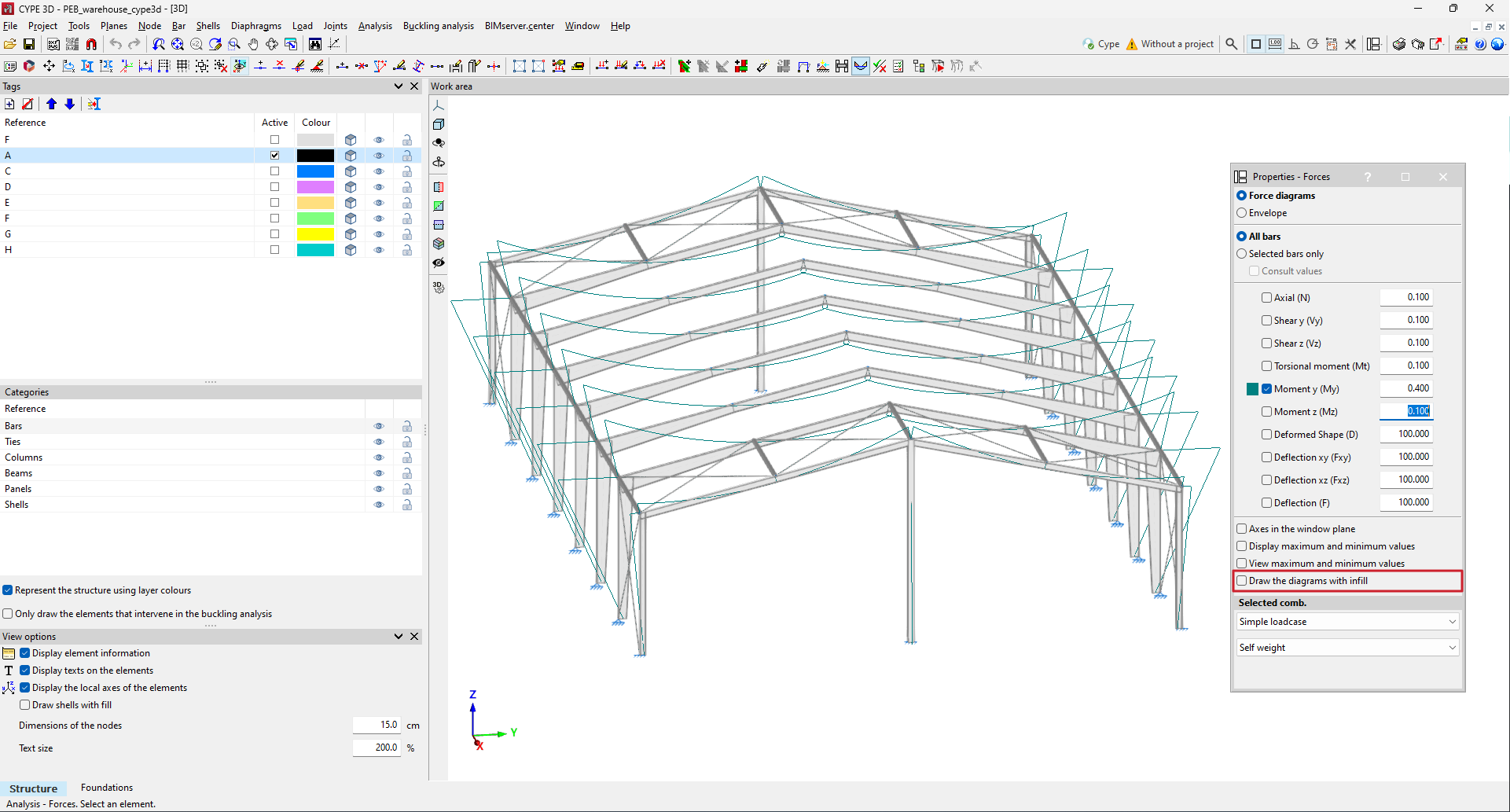
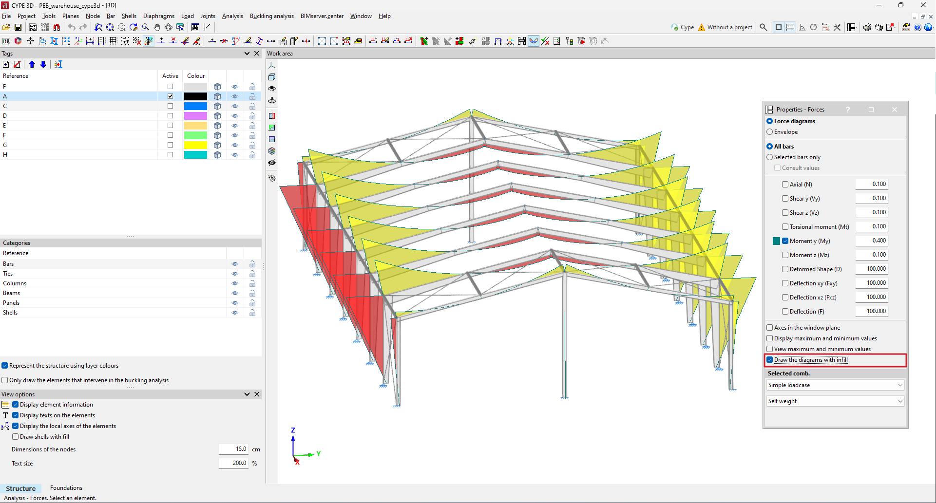
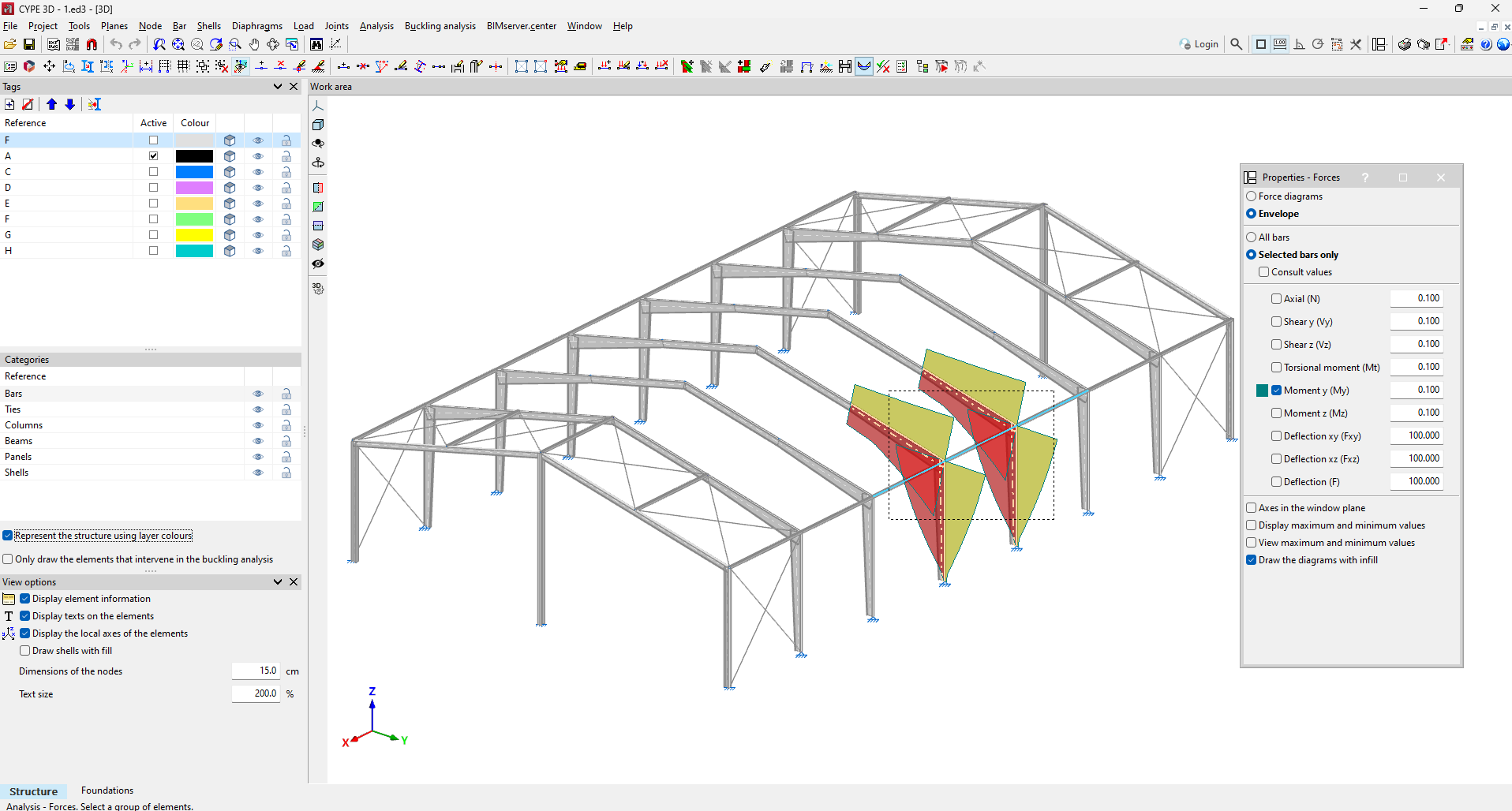
In version 2025.b, the option to draw filled force diagrams has been implemented.
In the "Forces" window, by activating the new "Draw the diagrams with infill" option, the drawing of the force diagrams will be filled with yellow and red colours for negative and positive values.
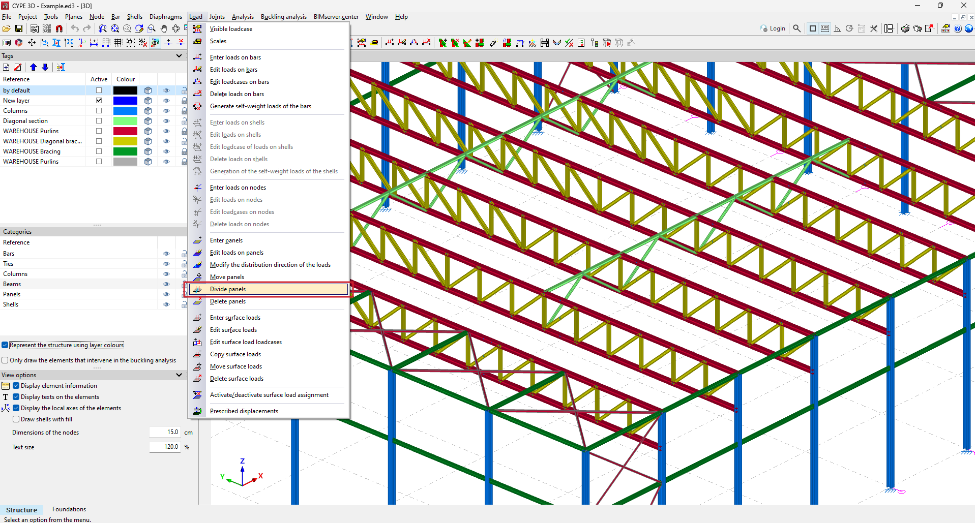
In CYPE 3D version 2025.b, the "Divide panels" tool has been implemented. This tool allows a panel to be divided in two by a straight line.
As well as dividing the panel, all surface loads associated with the panel are also divided. To split a panel, select the two points on the panel outline that define the splitting segment.
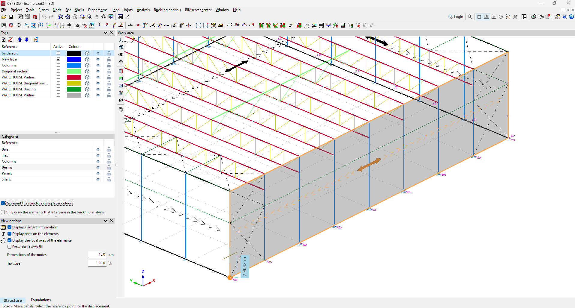
Until version 2025.b of CYPE 3D, when moving the vertices of a panel with the "Loads > Move panels" tool, the surface loads associated with the panel remained in their original position, forcing the user to move the surface loads as well.
As of version 2025.b, the surface loads will be automatically adjusted to the new position or geometry of the panel.
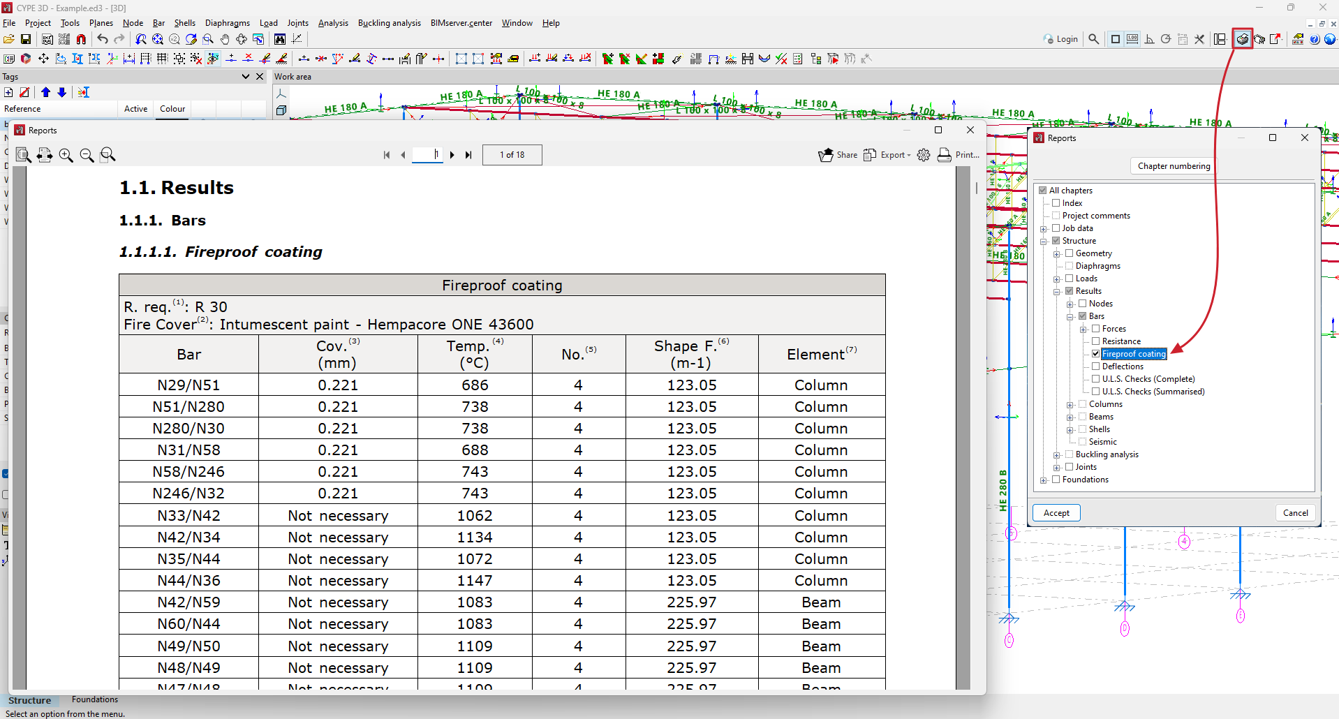
In CYPE 3D version 2025.b, a new report is implemented showing the fireproof coatings assigned to each bar.
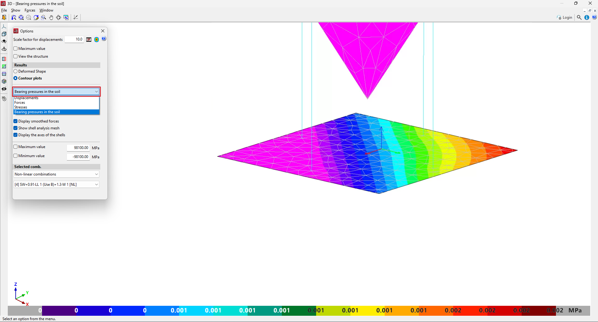
In CYPE 3D version 2025.b, the representation of contour plots of bearing pressures in the soil is implemented in the shells that have assigned subgrade modulus in their local z-axis.
As of version 2025.b, it is now possible to enter "Ibarra-Medina-Krawinkler" type plastic hinges in CYPE 3D. This hinge allows users to model a behaviour of strength and stiffness reduction after yielding by means of a Backbone type curve.
The "Plastic hinges" option in the "Bar" menu defines the plastic hinges' relative position and their properties, as well as the degrees of freedom of rotation on which they act. Up to version 2025.b, "Elastic-linear Hardening" plastic hinges could be defined. From now on, the new "Modified Ibarra-Medina-Krawinkler" type can also be selected.
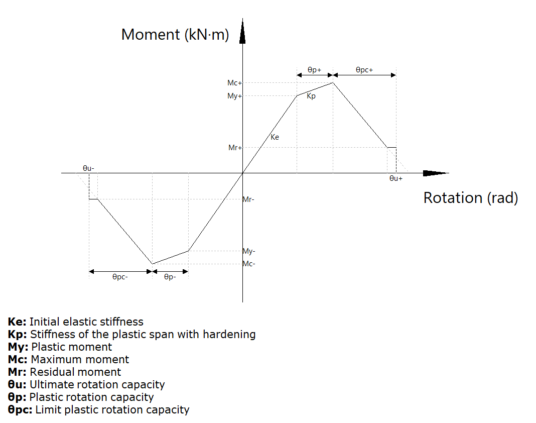
The data required to define the behaviour of a plastic hinge for a given degree of freedom of rotation are shown in the following image.
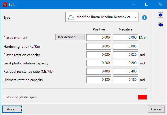
In the entry panel for the "Ibarra-Medina-Krawinkler" plastic hinge, there is an aid for visualising the behaviour curve and a legend of the symbols used in the curve.
In the stress display, plastic hinges that have reached the yielding point in the selected combination will be highlighted with an increase in size and a colour change.
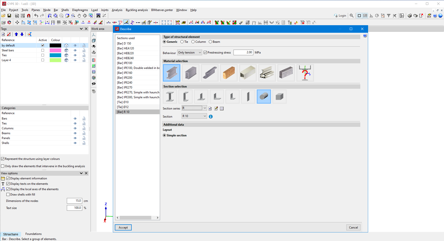
As of version 2025.b, a prestressing stress can be entered in CYPE 3D for bars only in tension.
This stress can be entered in the bar description panel.
As of version 2025.b, when displaying the forces of a selection of bars, the selection by rectangle of a set of bars is permitted as well as by bar.
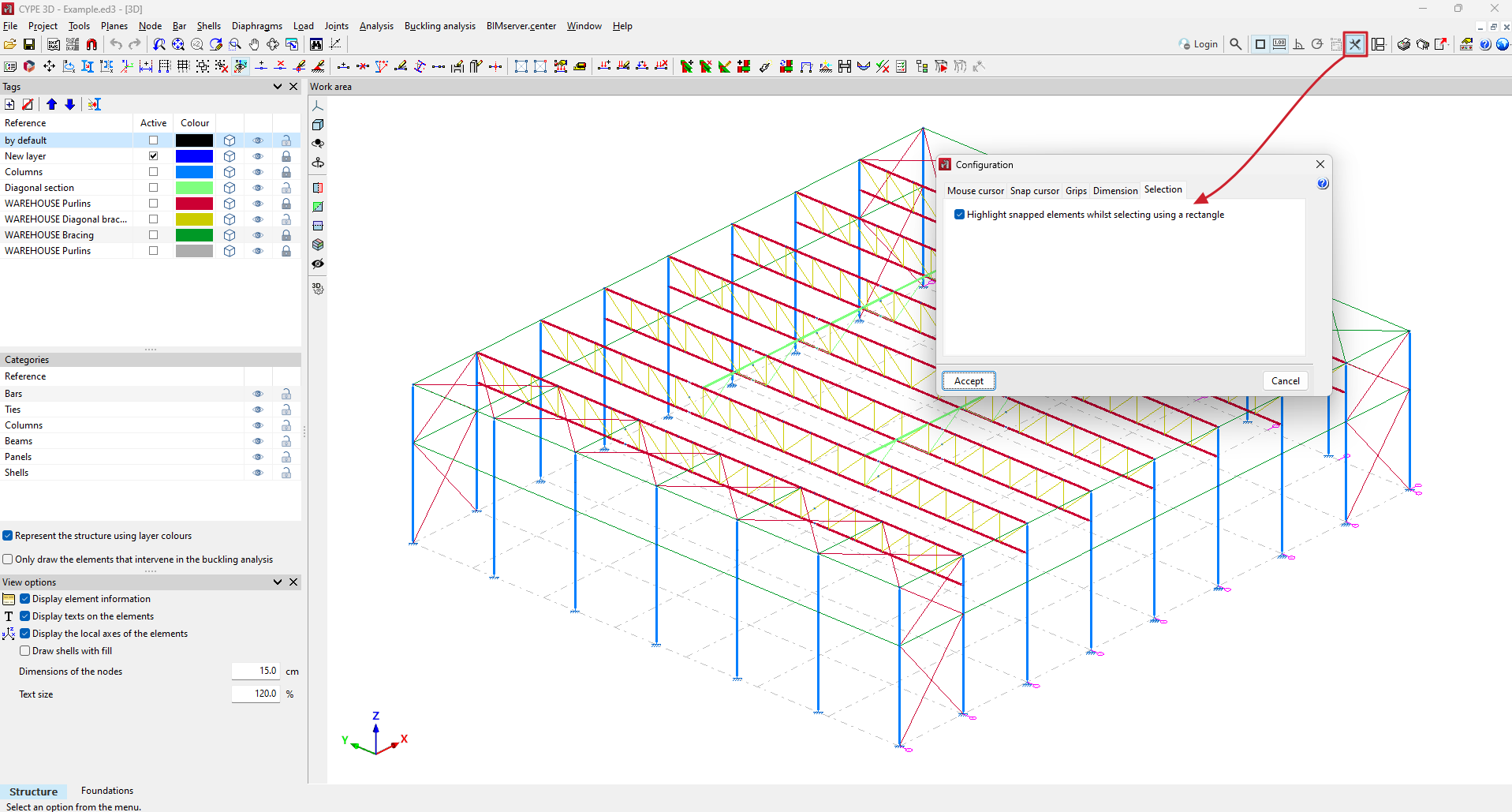
In version 2025.b, the option for highlighting or not highlighting objects when selecting using a rectangle has been implemented.
This option shall be activated by default. If the selection using a rectangle does not work smoothly when highlighting objects, it can be deactivated by the user.
As of version 2025.b, CYPE 3D can also be installed in German. The languages in which this application can be installed are now as follows:
- Bulgarian
- Catalan
- English
- French
- German
- Italian
- Polish
- Portuguese
- Portuguese (Brazil)
- Romanian
- Russian
- Spanish
- Spanish (Argentina)
- Spanish (Mexico)
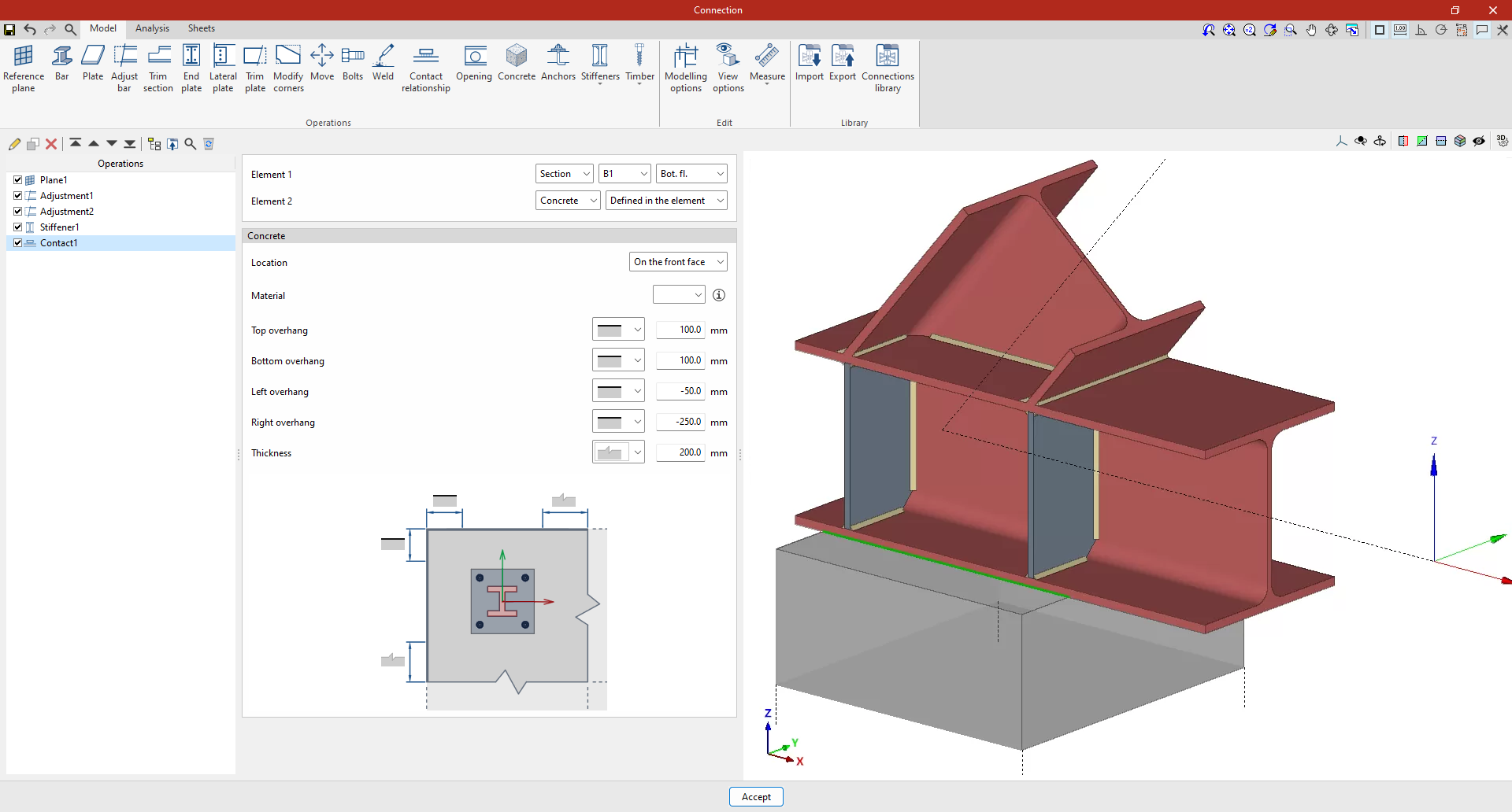
In version 2025.b the new "Contact relationship" operation has been implemented. This operation defines contact relationships between steel surfaces or between steel surfaces and concrete elements.
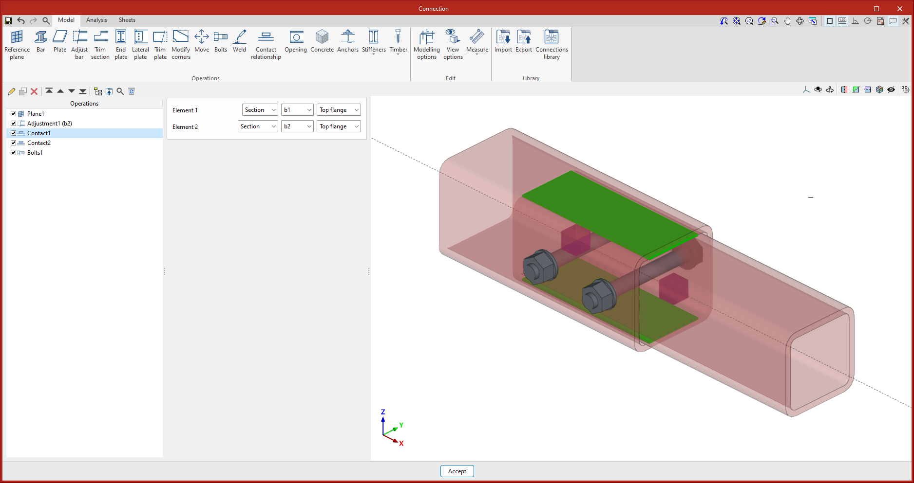
When bolting plates together, the program already establishes these contact relationships automatically, as when anchoring a plate to a concrete element. This new operation can also be carried out without the need to add bolts or anchors. In the design model, non-linear relationships are established between the nodes of the mesh of the plates, which only work in compression.
This operation is represented in the 3D view by a green surface between the elements selected in the operation. When selecting contact between a plate and a concrete element, users will be allowed to select an existing concrete element or a new element defined in this operation.
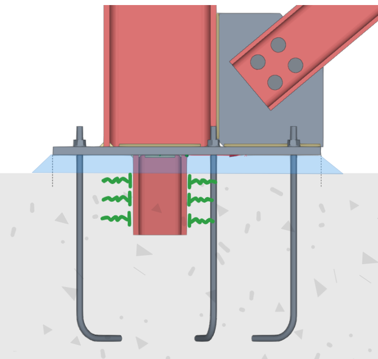
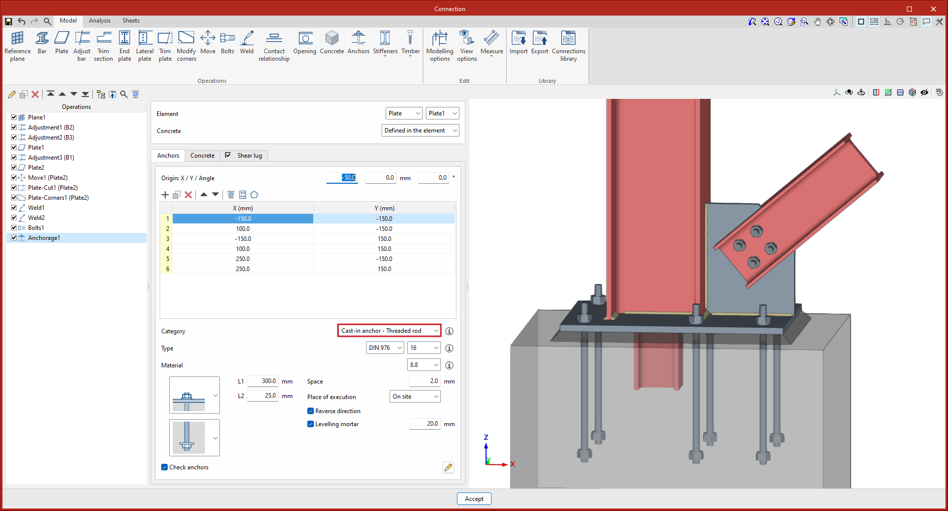
In version 2025.b, an option to include shear lugs to baseplates has been implemented in the "Anchors" operation.
In baseplates, particularly when shear forces are considerable and users prefer not to transfer them to the foundation via the bolts, a shear lug is often installed. This element consists of a steel section, welded to the bottom of the plate, embedded in the foundation, the purpose of which is to transmit shear forces directly to the foundation element and thus free the bolts from transmitting this force and working exclusively in tension.
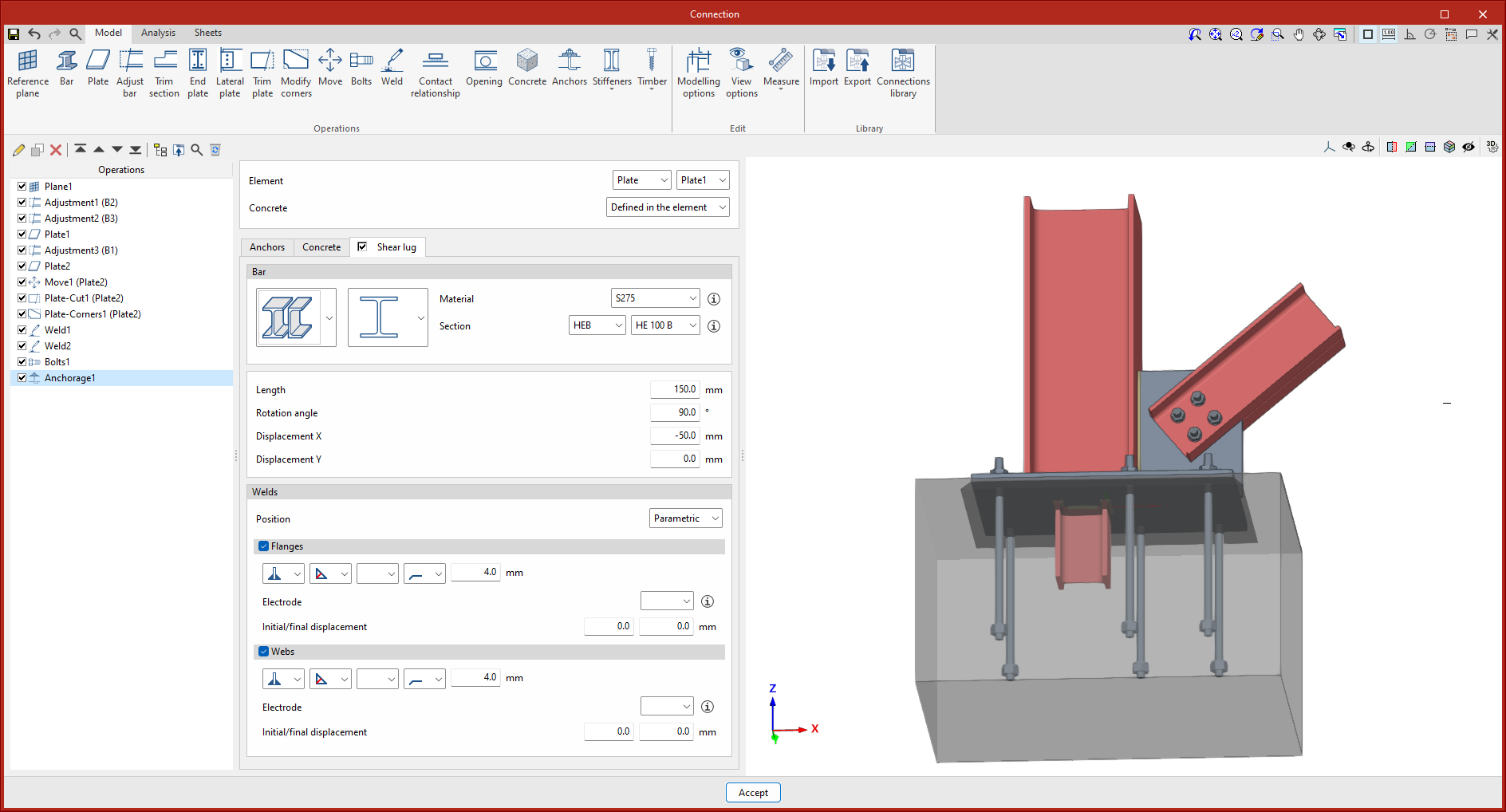
The verification of the strength of the concrete element for shear lugs is carried out by means of the compressive strength on the lug faces.
Users must check whether the concrete element has enough reinforcement to withstand the forces transmitted by the shear lug.
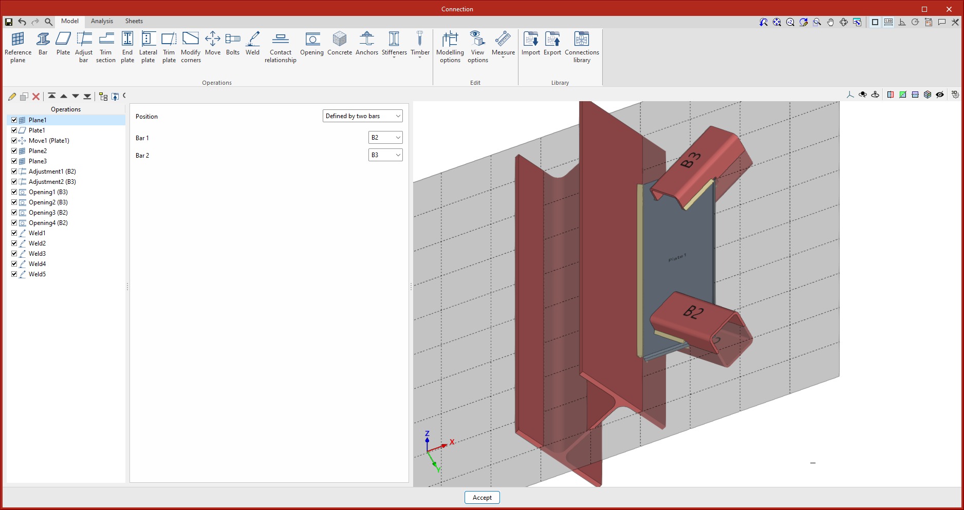
In version 2025.b, a new reference plane positioning option has been implemented: "Defined by two bars".
With this option, if the two selected bars are contained in the same plane, the reference plane will be created in the plane formed by the two local 'x' axes. When the bars are not contained in the same plane, the reference plane will be created at the midpoint of the origin of both bars.
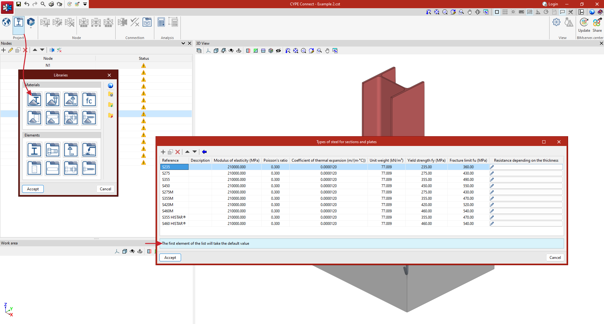
In versions before 2025.b of CYPE Connect and StruBIM Steel, the selection of library elements (sections, materials, bolts, anchors, etc.) worked with two buttons. One contained the data to be used and could be modified; the other (represented by three dots) was used to obtain the library data. This method made it possible to modify or edit the data directly, but once defined or imported, they were not related to the library, so if changes were made in the library, they were not reflected in these elements. Furthermore, the library selection was not direct, a new panel was opened, forcing the user to click the mouse several times to select an element.
As of version 2025.b, the selection of library elements or materials is simpler and faster, as it is done directly from a drop-down button. An information button showing the selection data is also included. If data is modified in the library, it is also modified in all the elements that have that selection.
The default value of each drop-down button will correspond to the first element in the library lists. For example, if users want material S275 to be the default value in the "Types of steel for sections and plates" panel in the material library, it must be placed in the first position of the table.
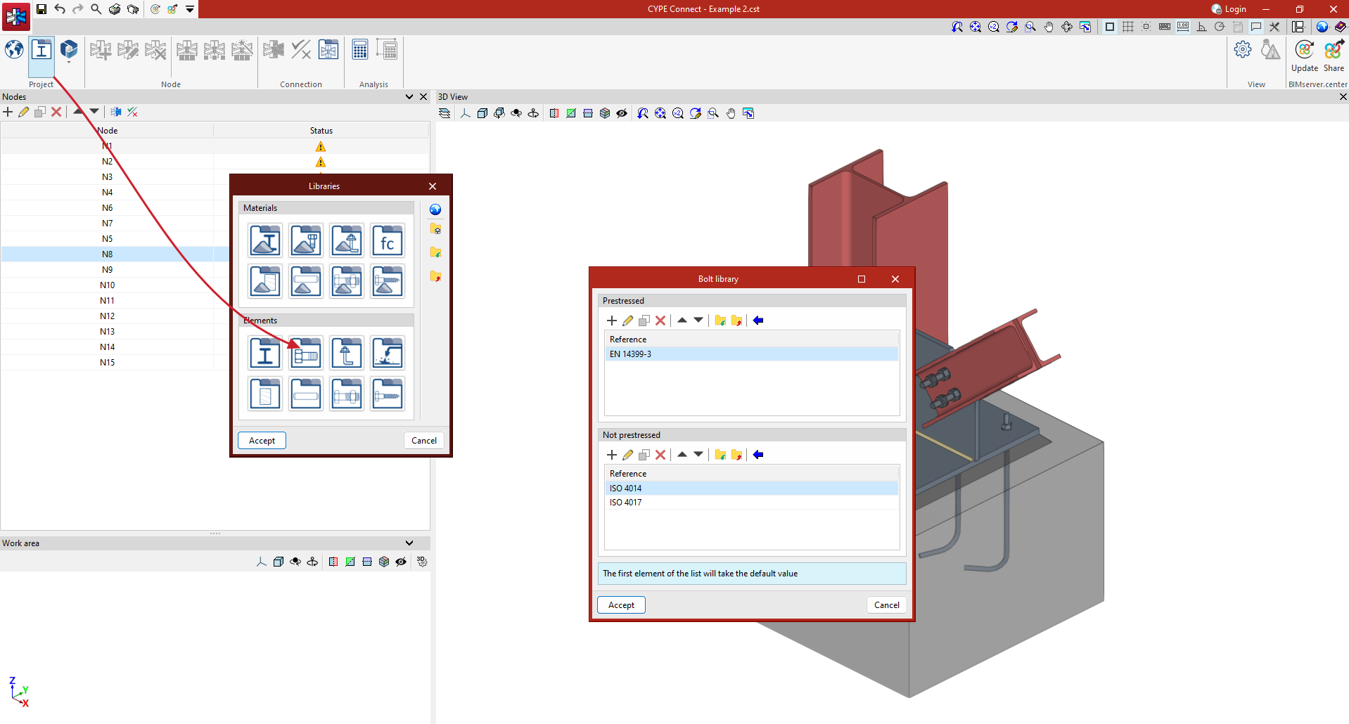
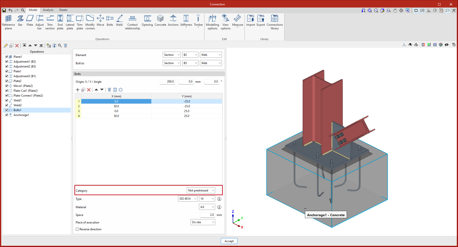
The bolt and bolt material libraries are divided into two libraries, one for prestressed bolts and one for non-prestressed bolts.
The selection of bolt types will also include the category selection, prestressed or non-prestressed.
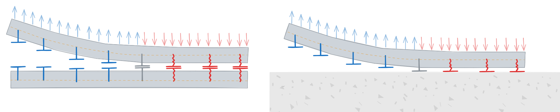
In versions before 2025.b, baseplates or sections with anchors on one of their faces had to be fully supported over their entire surface.
As of version 2025.b, connections where the slab is partially supported by the concrete element can be designed.
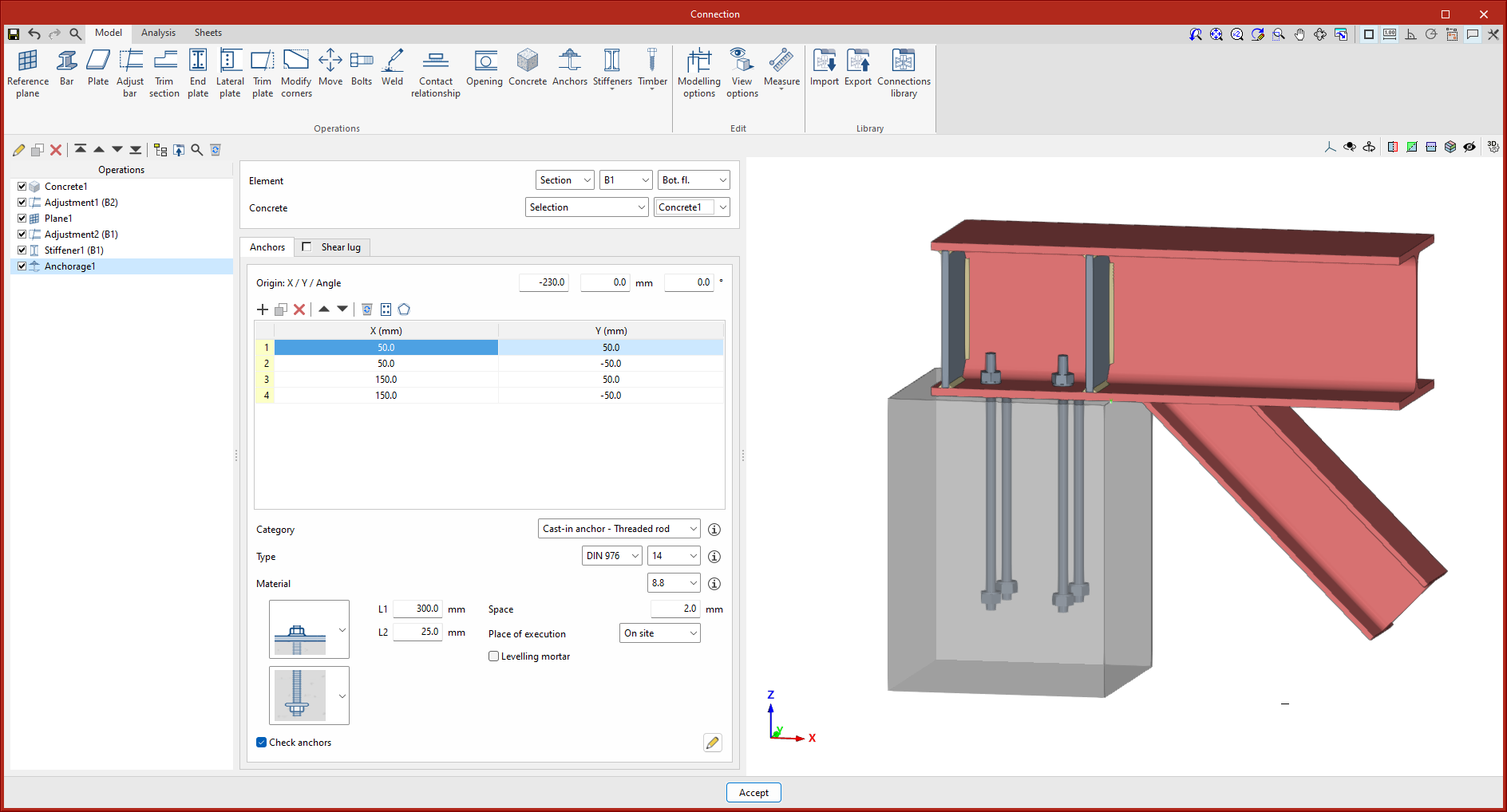
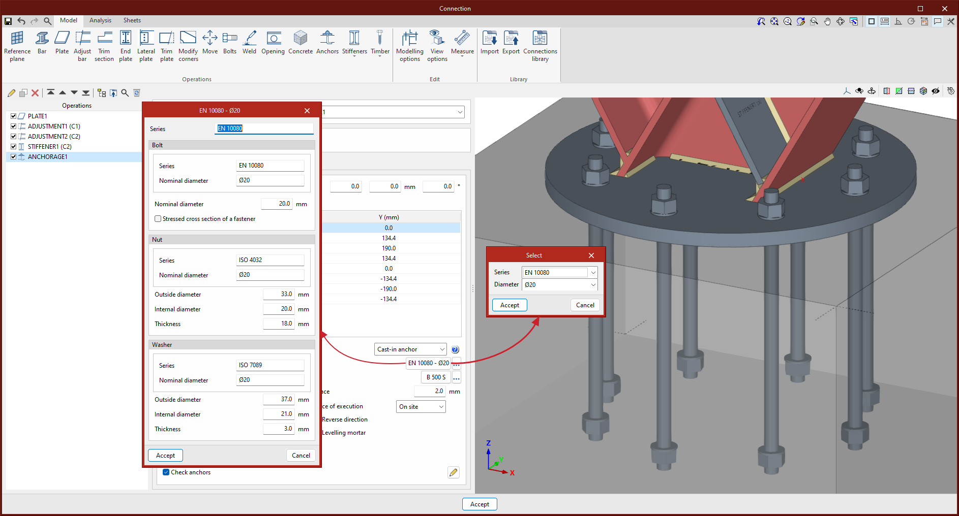
New types of headed anchors have been implemented. Corrugated bars and smooth bars can be finished with a square or circular plate welded on the end. For threaded rods, ends with a stop nut and plate, with or without a locknut, have been implemented.
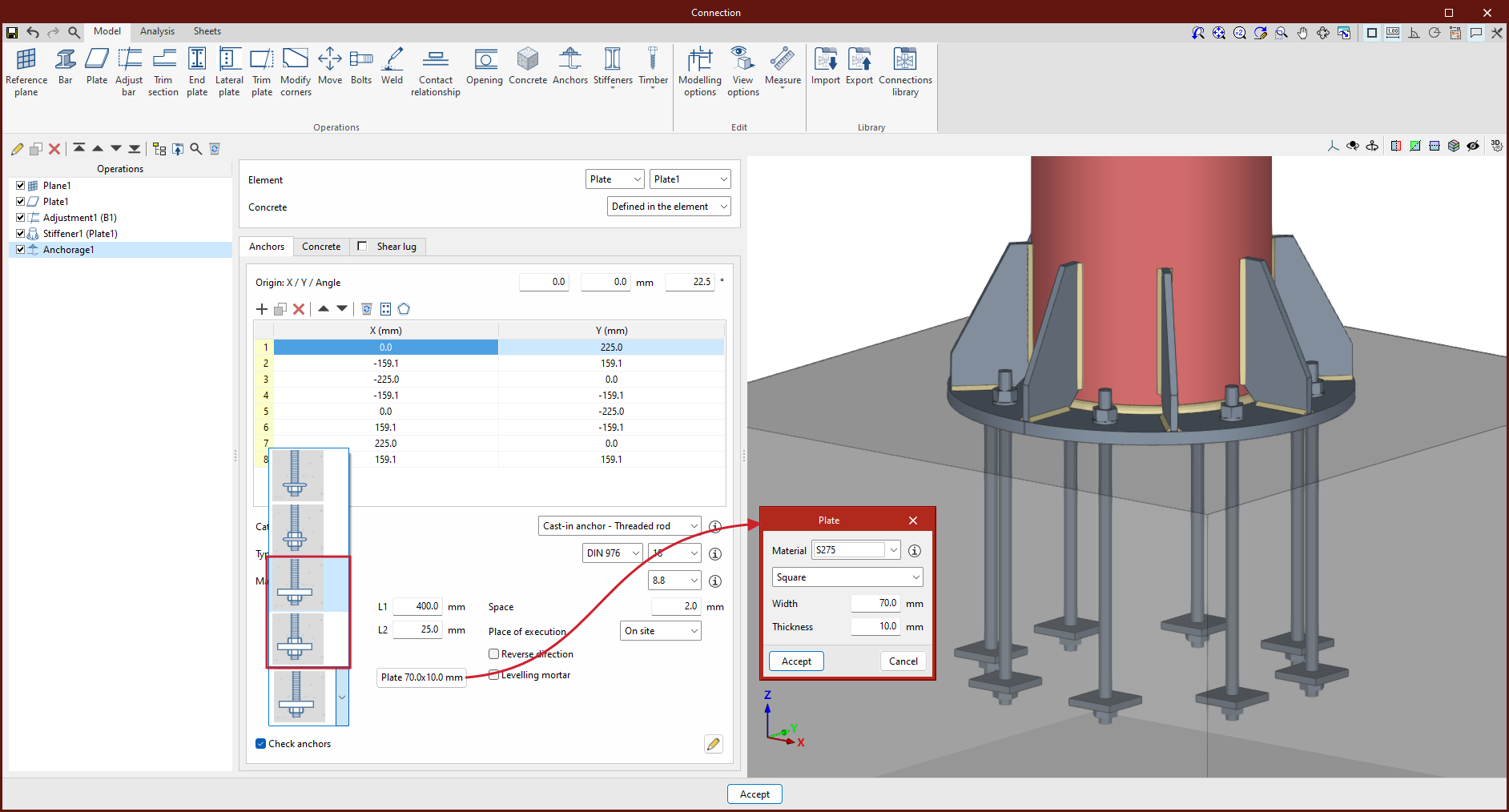
The head area is considered in the corresponding checks and the sheet is not added to the finite element model.
In version 2025.b of CYPE Connect and StruBIM Steel, a section with optional checks for anchors has been added to the "Check anchors" panel.
This way, users can select which checks they need to carry out for the connection to be analysed.
This new feature is available for all concrete codes that are implemented in both programs.
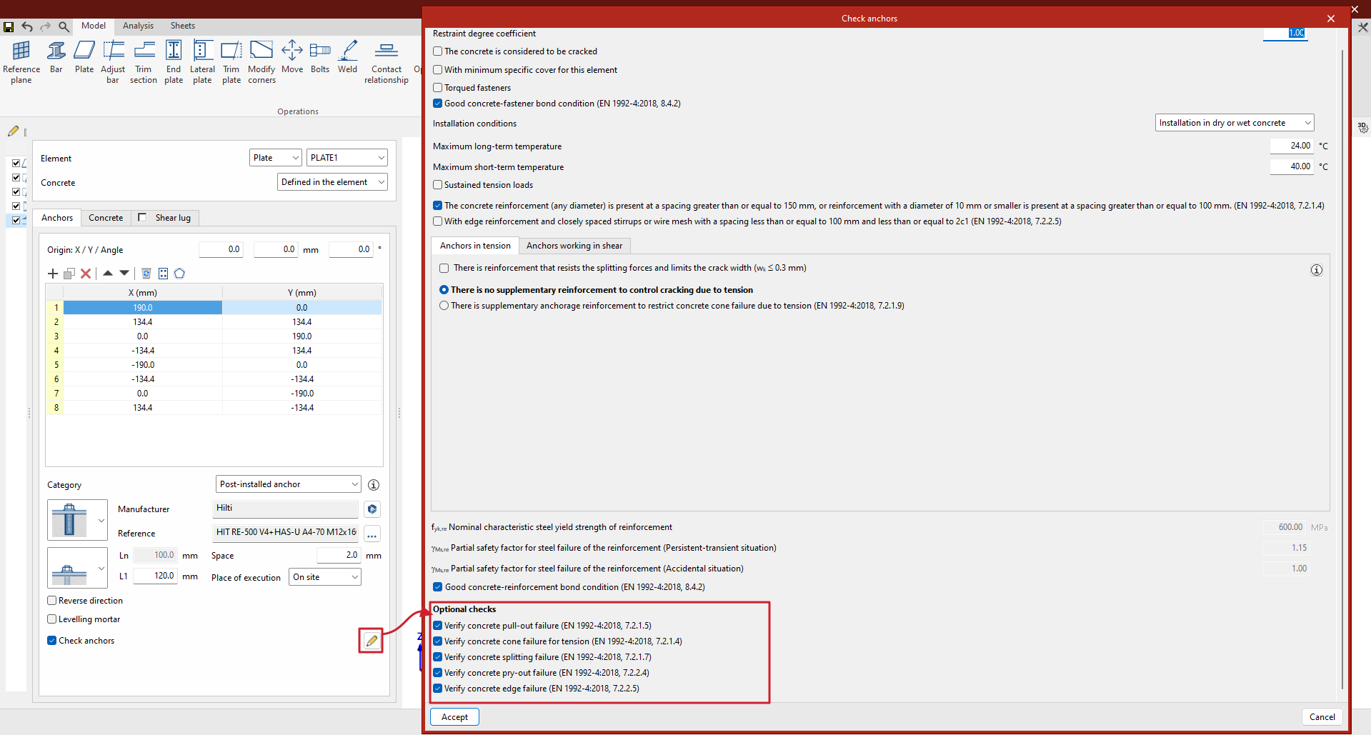
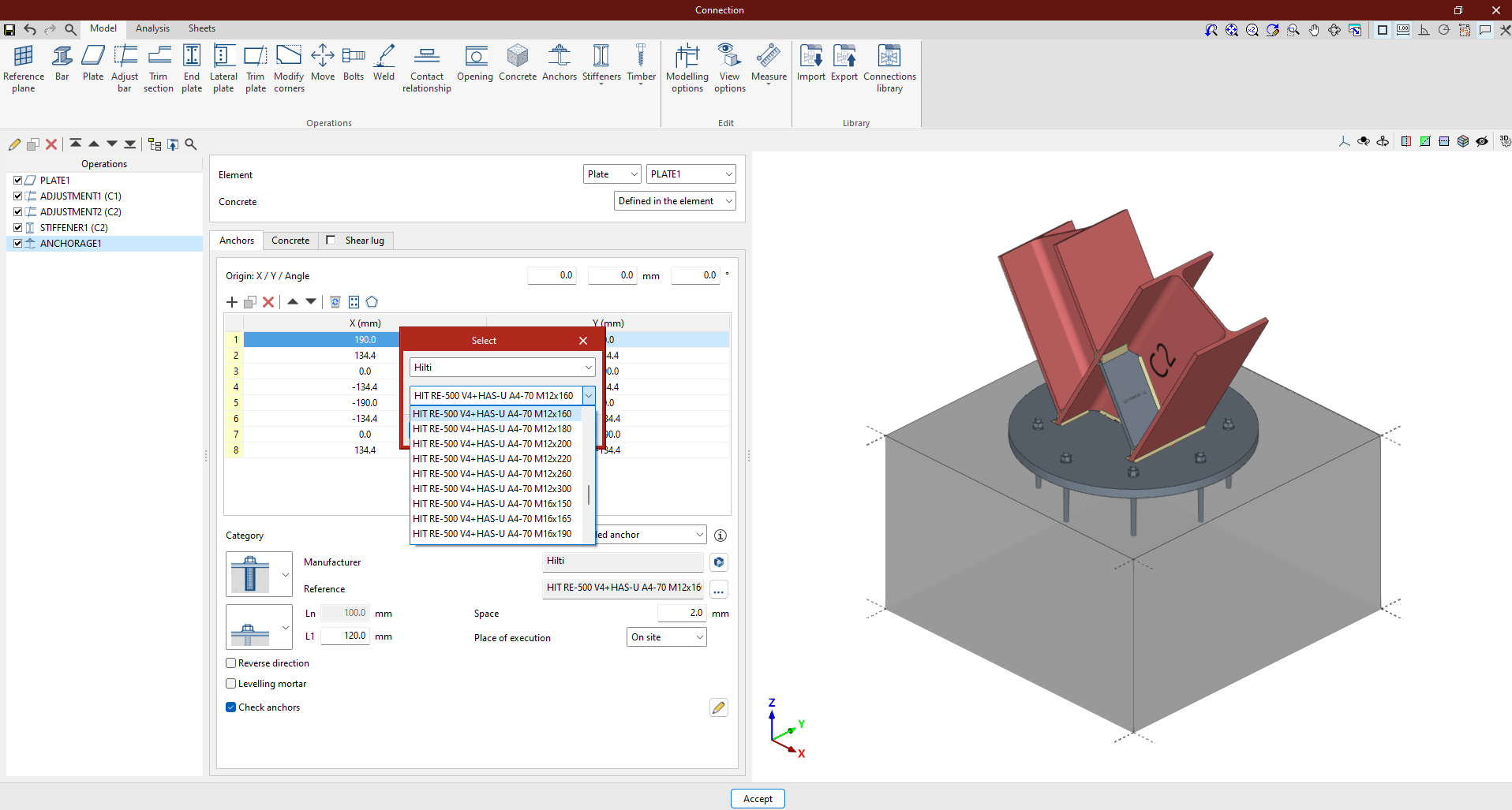
In version 2024.d, HILTI brand chemical and mechanical anchors for concrete fixings were incorporated into CYPE Connect and StruBIM Steel. Now, in version 2025.b, the catalogue of HILTI anchors has been extended with the addition of HIT RE-500 V4 post-installed chemical anchors, with HAS-U A4 anchor rods.
These elements are checked according to the criteria of EN 1992-4:2018, based on the data provided in the ETAs (European Technical Assessment) of these anchors.
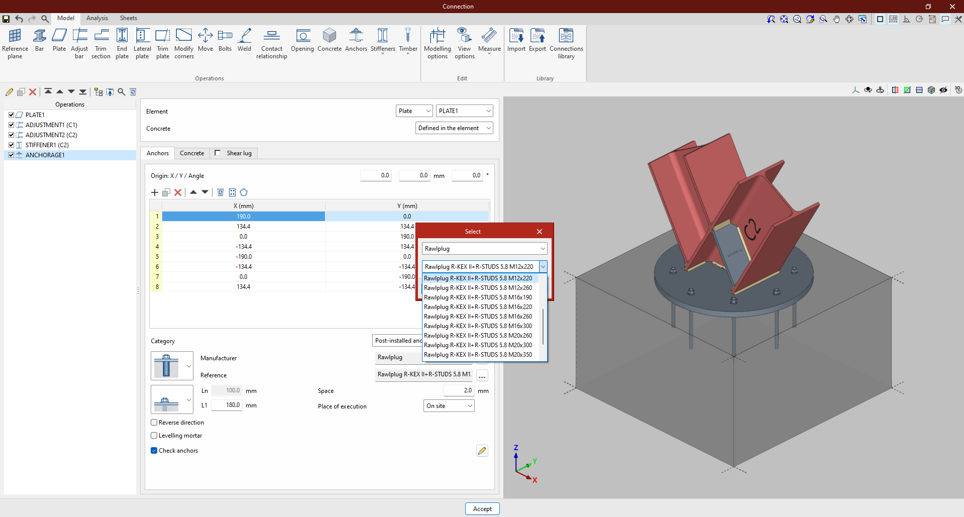
In CYPE Connect and StruBIM Steel version 2025.b, there is now the possibility to use post-installed RAWLPLUG branded chemical anchors as concrete fixing elements in baseplates.
These elements are checked according to the criteria of EN 1992-4:2018, based on the data provided in the ETAs (European Technical Assessment) of these anchors.
The post-installed anchors incorporated in version 2025.b are the following:
- Chemical fixings
- Torque-controlled expansion anchors
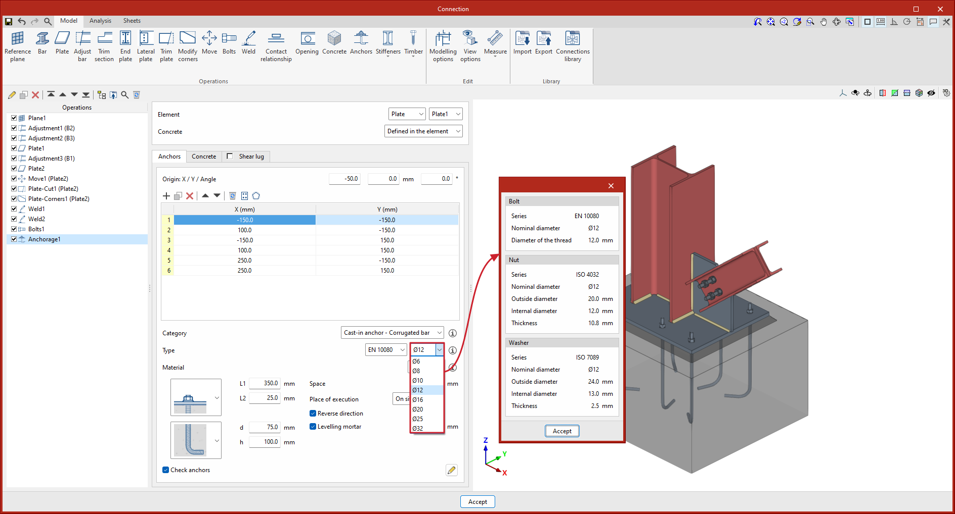
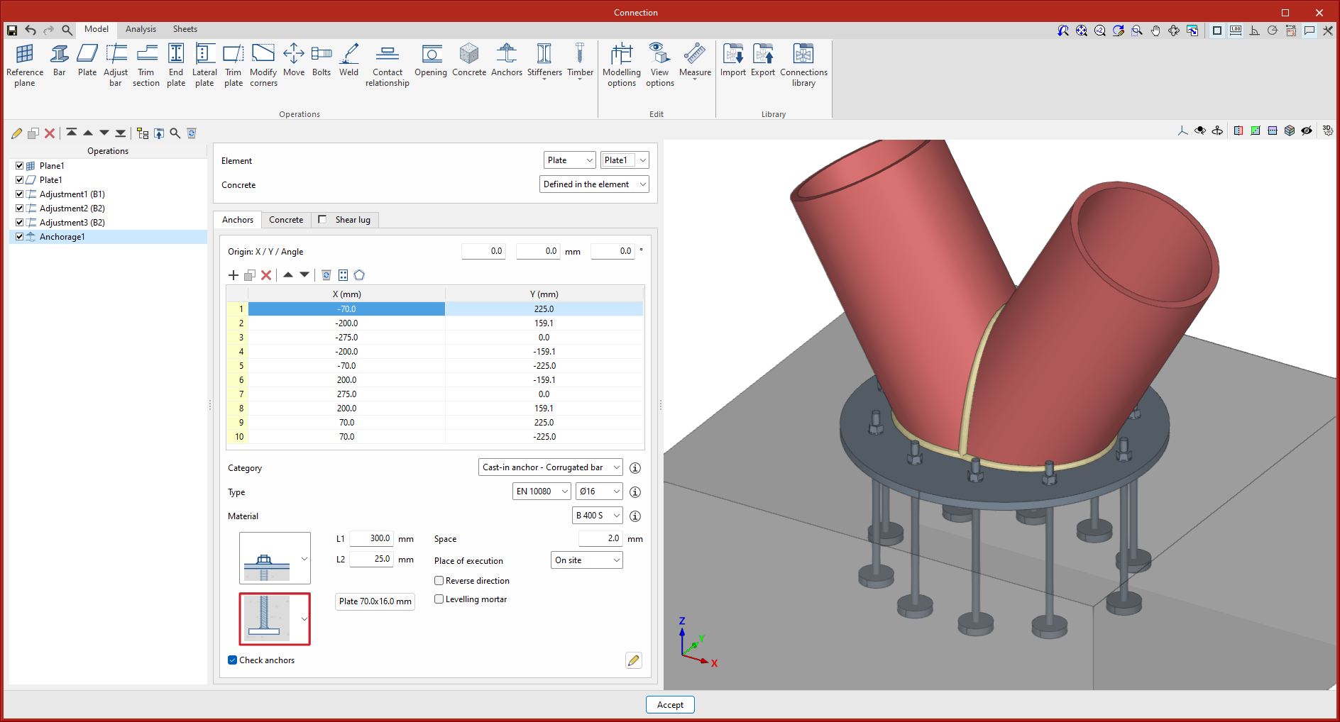
In versions before 2025.b, the program had a library of anchor series and a library of anchor materials. These libraries did not specify the type of bar (corrugated bar, threaded rod, smooth bar, etc.). When the program checked straight anchors or anchors with 90° bends or 180° bends, these anchors were considered as corrugated bars directly.
As of version 2025.b, the libraries of anchors and anchor steel types are divided into three libraries, one for corrugated bars, one for threaded rods and one for smooth bars. The anchor selection will also include the type of bar. The type of anchor determines the type of bar selected. For example, threaded rods and bent-bar anchors may not be selected.
This improvement allows users to guide data entry and makes it easier to select compatible options.
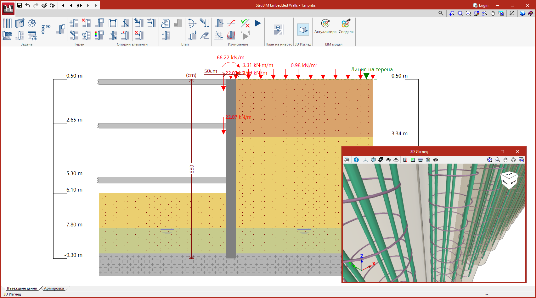
As of version 2025.b, StruBIM Embedded Walls can also be installed in Bulgarian, and StruBIM Cantilever Walls can be installed in Bulgarian and Russian. The languages in which both applications can be installed are now as follows:
- Bulgarian
- Catalan
- English
- French
- Italian
- Polish
- Portuguese
- Portuguese for Brazil
- Russian
- Spanish
- Spanish for Argentina
- Spanish for Mexico
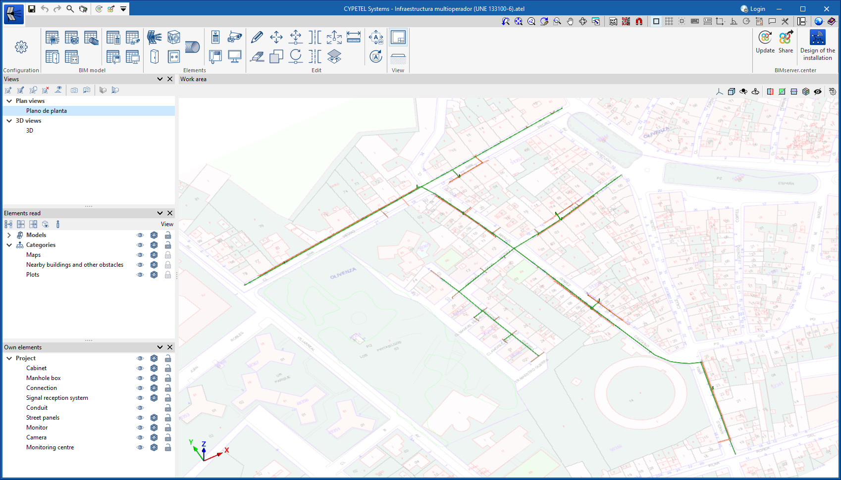
The new job “Infraestructura multioperador” has been included.
This job shows the design of a multi-operator telecommunications infrastructure, according to the UNE 133100-6 standard, in order to allow a municipality to install telecommunications networks.
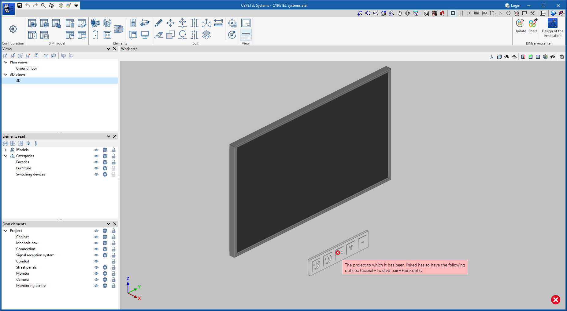
As of version 2025.b, CYPETEL Systems can read the telecommunications mechanisms defined in CYPELEC Electrical Mechanisms.
CYPETEL Systems requires a definition of the outlets in the spatial position where they are located in the project.
To use this feature, when creating a job in CYPETEL Systems, users will need to link to a BIM project and import the contribution with the information from CYPELEC Electrical Mechanisms.
For faster linking, CYPELEC Electrical Mechanisms features an option to access CYPETEL Systems directly.
The process of importing a BIM model when the job is linked to a BIMserver.center project has been updated.
Now the first steps in the import process are the selection of codes and the downloading of manufacturer's catalogues in order to have an optimal configuration of all the elements needed to carry out the hydraulic design and analysis.
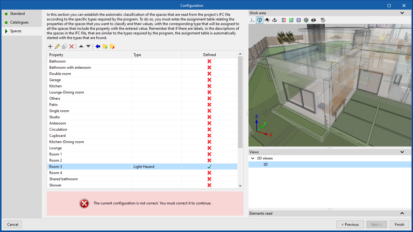
Finally, the necessary spaces are imported in order to carry out this design. To do this, all the spaces of the architectural model are imported, grouping them in the easiest way for the user according to the different entities defined in the .ifc.
Once all the spaces have been imported, the risk equivalent to the imported code is assigned. On the right, the enclosures that are being worked with can be seen in the 3D model of the building.
All the spaces imported into CYPEFIRE Hydraulic Systems are considered as spaces where the fire protection design is to be carried out, therefore, all those that should not have the system should not be imported. When reading the old job, an error will appear for the imported spaces that do not have this system; they should be deleted or the hydraulic system design should be carried out.
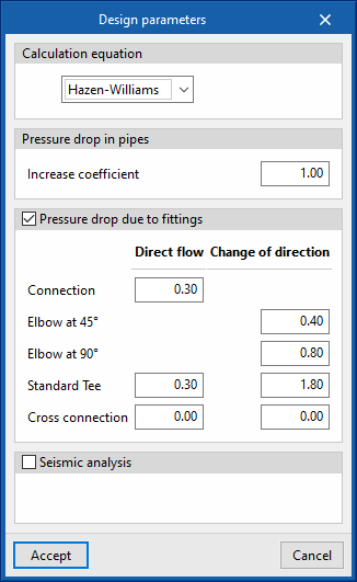
The creation and measurement of fittings (elbows, tees, junctions, crosses) has been optimised.
Up until now, these fittings could be entered automatically or manually by entering the losses in the corresponding pipes and, based on their losses, the quantities of these fittings were generated.
As of version 2025.b, the 3D representation of the individual fittings in the "Design parameters" panel will be available and the correct angle of the pipes or the number of connections will be checked for each of them.
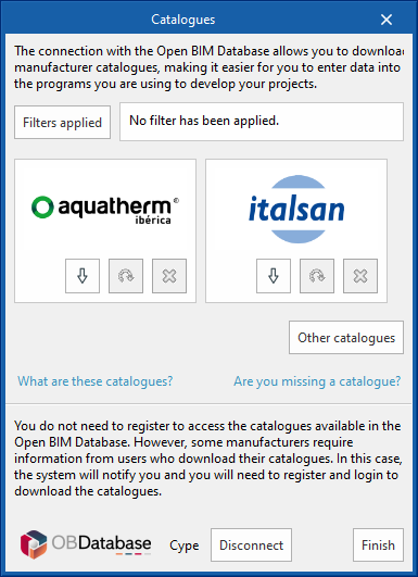
In earlier versions, in the “Project” menu, there is a "Catalogue management" option for downloading manufacturer products.
New types of manufacturer products are added in this version, from the following available categories:
- Sprinklers
- Pipes
- Booster sets
- Fire hose reels
The generic catalogues have also been moved within the same menu to the “Library of generic elements” option, which allows users to continue to include the required units.
When starting a new project, the option for incorporating the catalogue of some of the available manufacturers appears. If none are downloaded, the application includes the generic catalogues that are missing in order to start a system with all the necessary elements.
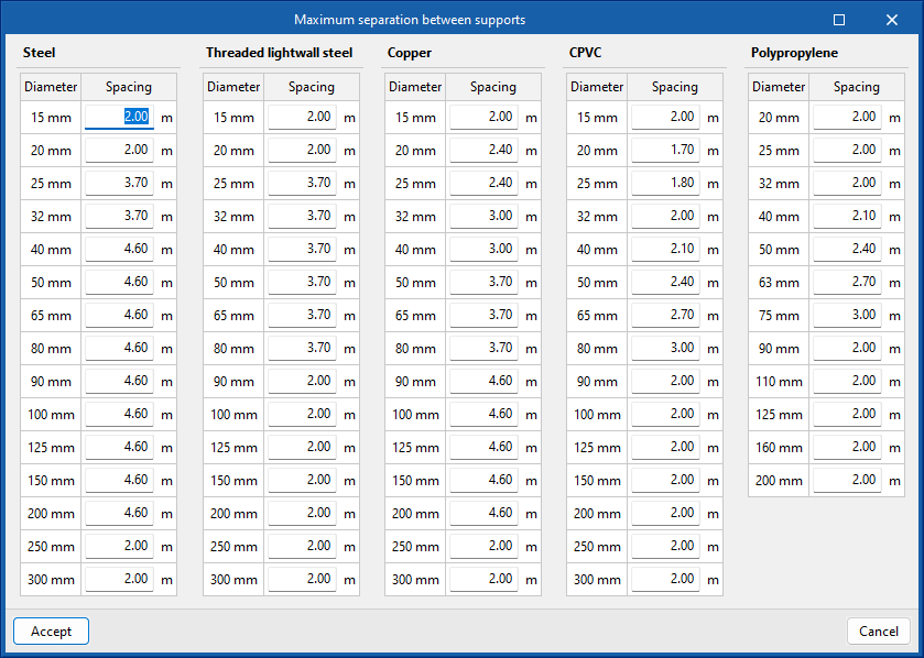
Up until now, entering supports for the pipe system has been a tedious process. As of version 2025.b and thanks to the latest changes to the application, this process of determining the quantities of supports is now completely automatic.
This is managed from the “Generate the support quantities” panel, accessible from "General options > Pipe options" in the main interface.
From now on, the support quantities will be generated automatically according to the pipe diameters entered and the maximum spacing specified.
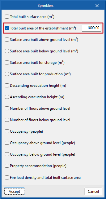
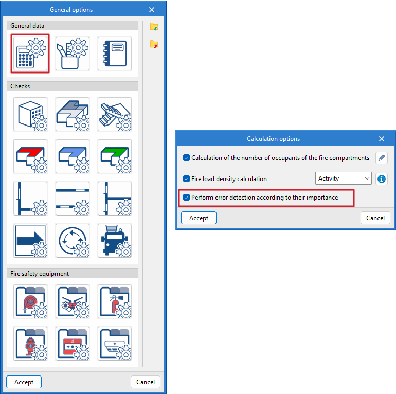
In the CYPEFIRE code configuration, each piece of fire safety equipment (fire extinguishers, hydrants, detectors, alarm buttons, etc.) can be requested according to different parameters such as the surface area of the compartment, ascending evacuation height, etc.
As of version 2025.b, CYPEFIRE now includes the possibility of requesting any of the equipment depending on the total surface area of the establishment where the fire compartment is located.
The existing codes have also been updated with this new check.
CYPEFIRE displays errors according to the level of severity defined in the program, allowing them to be solved in stages by focusing on only one part of the problem at a time.
However, this may not be a beneficial solution for some users, and for this reason, it is possible to deactivate this option and display all the errors of the work simultaneously. This option can be found under "General options > Design options".
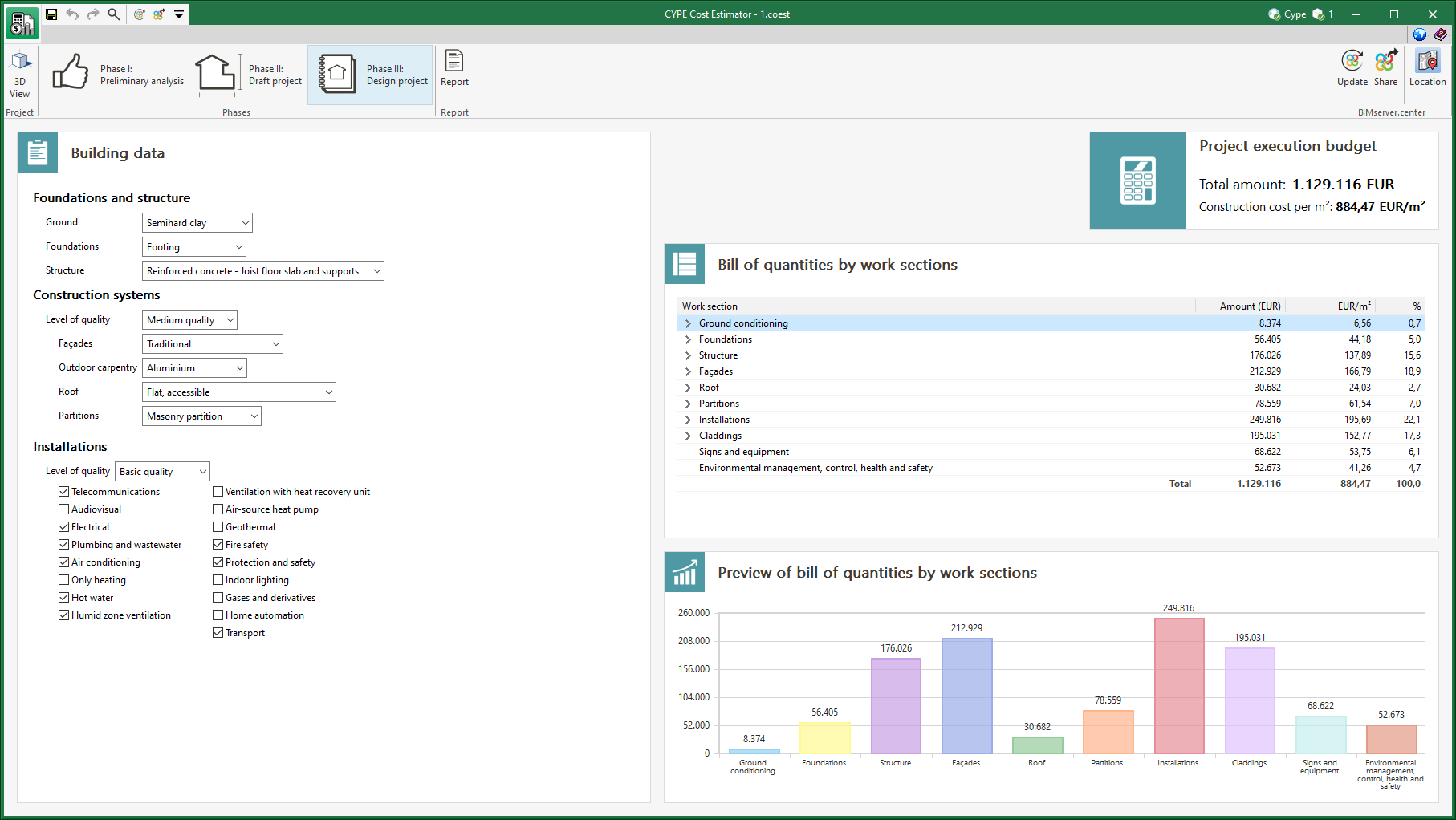
The price database used by the application to determine the total construction cost has been revised and updated.
Projects created with earlier versions of the program will be automatically updated when they are opened with version 2025.b.
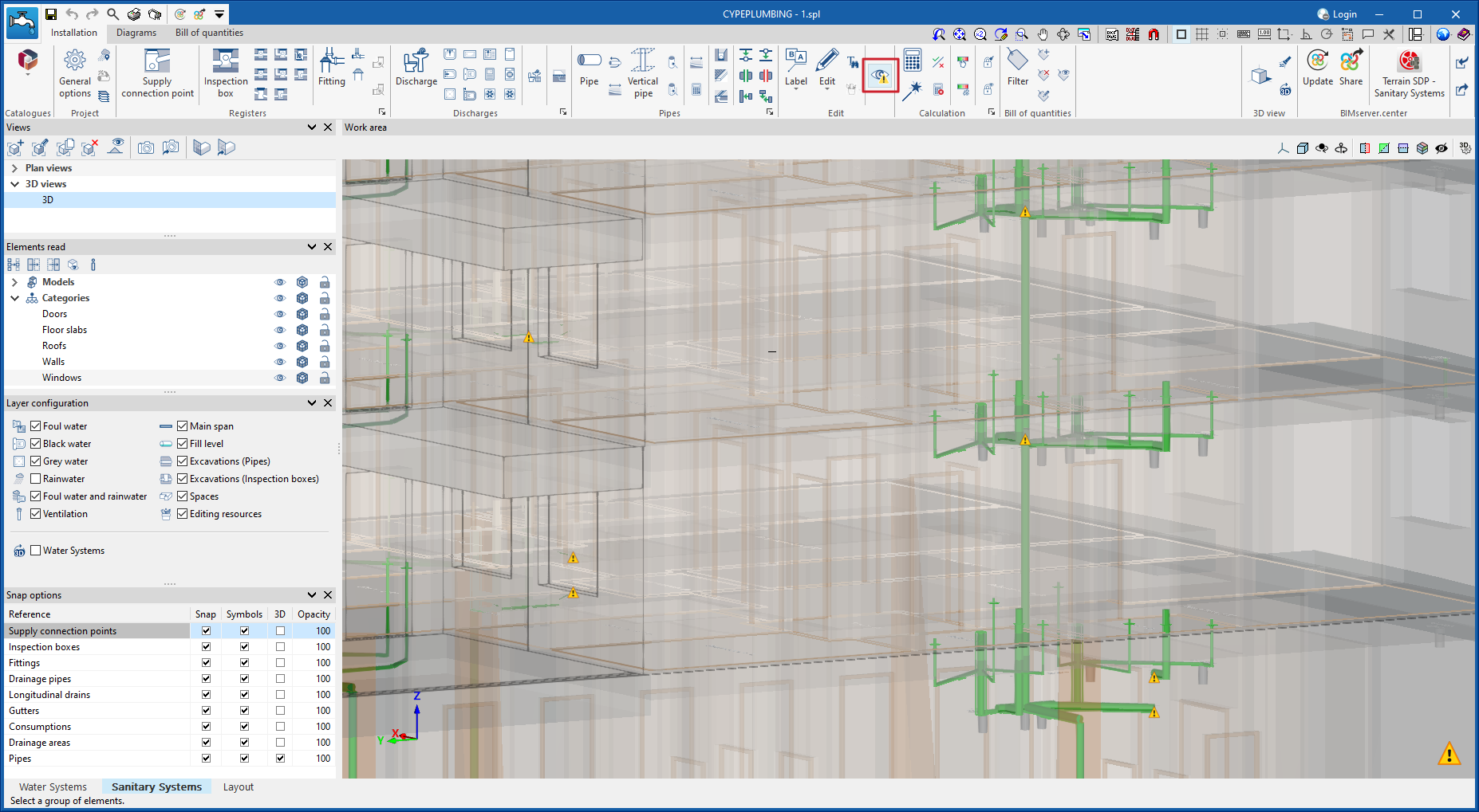
In the "Water Systems" and "Sanitary Systems" tabs of "CYPEPLUMBING", a new feature has been implemented that allows users to review the installation paths when they are being designed.
In previous versions, this review was performed when starting the analysis, which meant that the information on connection errors appeared when all the installation paths had already been entered.
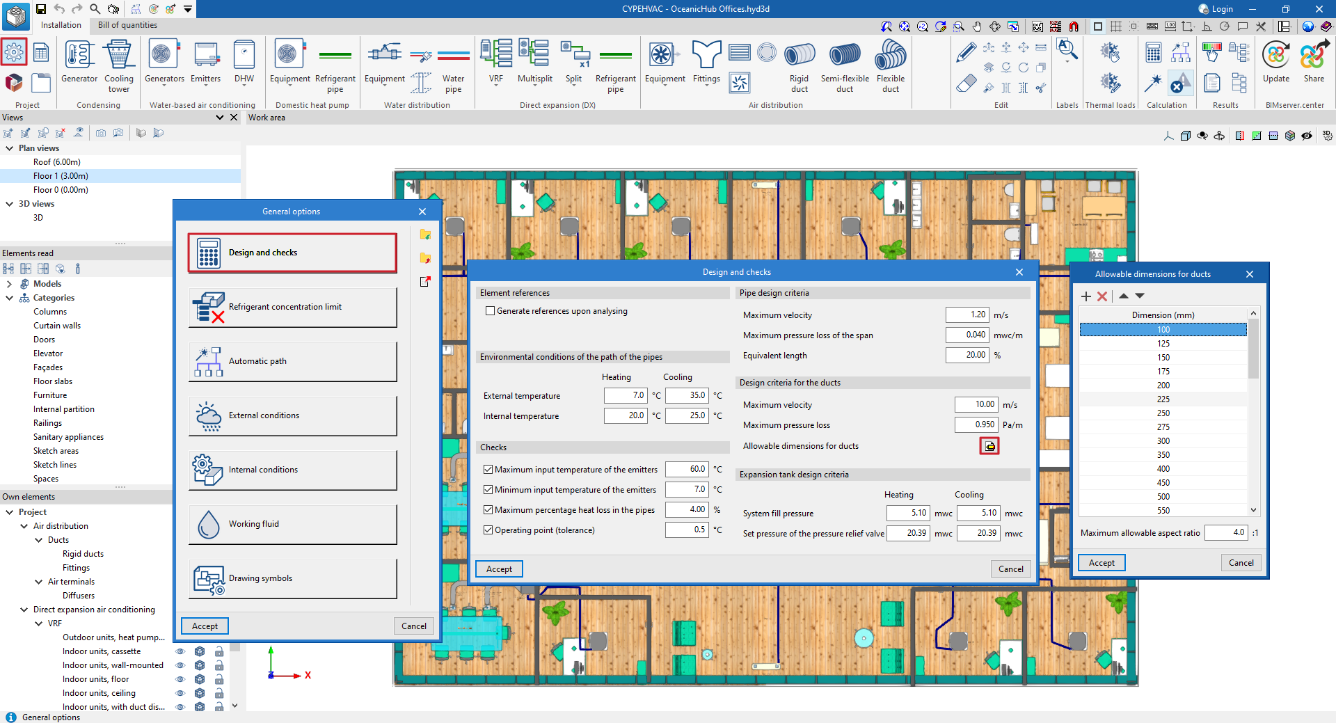
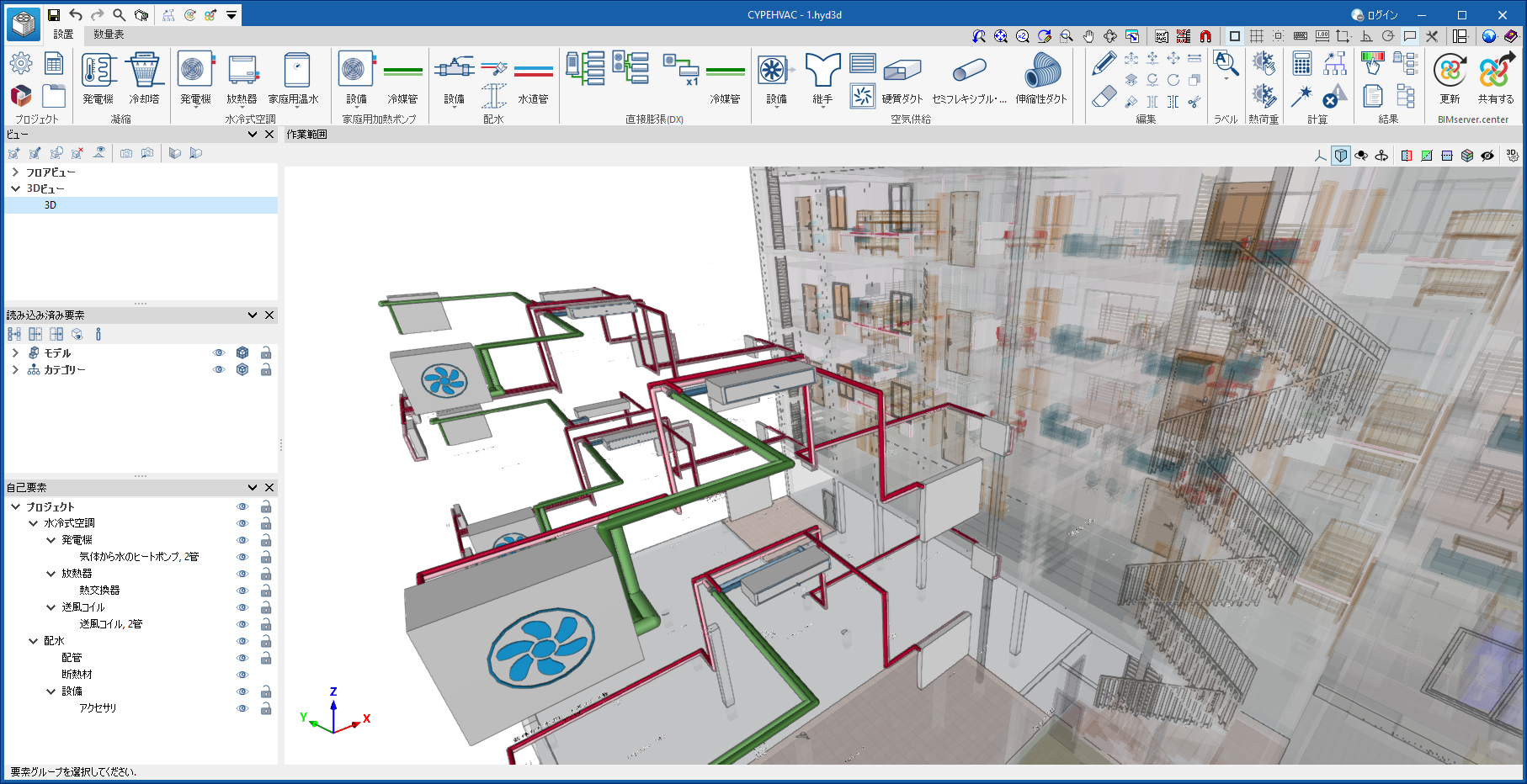
The definition of air ducts has been improved. Now, in CYPEHVAC version 2025.b, they are classified as rigid ducts, semi-flexible ducts and flexible ducts.
For rigid ducts, users can choose customised rectangular ducts (specifying their width and height), rectangular section ducts or circular section ducts. For semi-flexible and flexible ducts, users can select ducts with rectangular or circular sections.
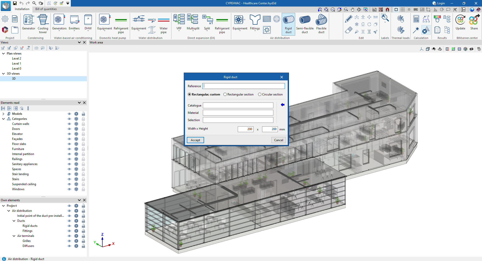
When designing the job, the program checks whether the selected ducts meet the criteria for duct design indicated in "Design and checks". If, instead of analysing the system, it is designed, the program selects the ducts with the smallest section that comply with this criteria. For customised rectangular rigid ducts, the program selects the smallest dimension (width and/or height) of the admissible duct dimensions indicated in "Design and checks".
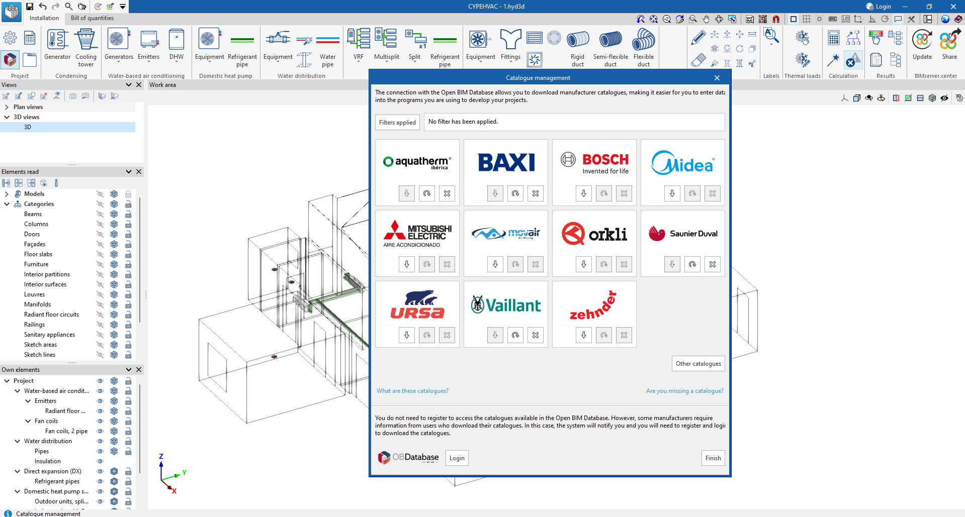
Since previous versions, in the "Project" menu, there is a "Catalogue management" option for downloading manufacturer products.
In this version, rigid, semi-flexible and flexible ducts from different manufacturers have been added. Furthermore, the generic catalogues are still available in the "Library of generic elements", where it is possible to continue to include the necessary conduits.
With the "Catalogue management" option, the Baxi, Bosch, Daikin, Fujitsu, Midea, Mitsubishi Electric, Saunier Duval, Saunier Duval and Vaillant fan heater system catalogues can be downloaded.
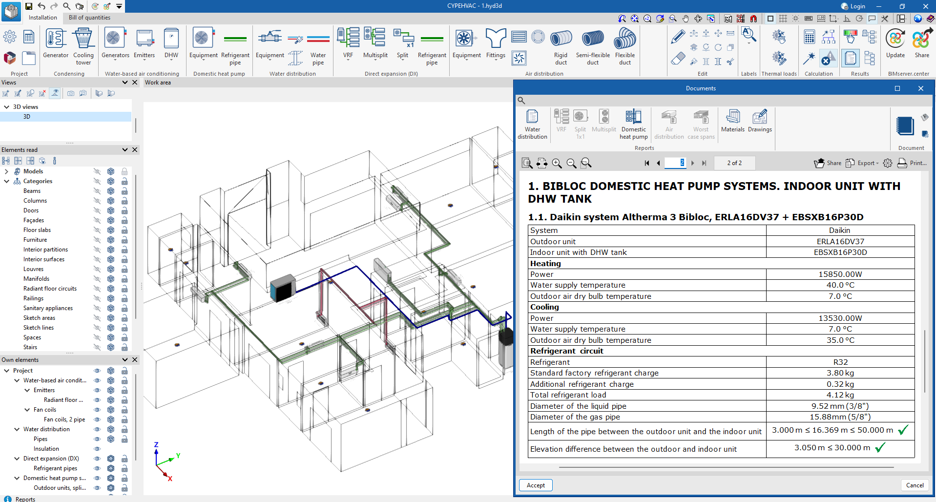
In version 2025.b, these products are available under the "Equipment" button in the "Air source heat pump" section of the toolbar, and monobloc and bibloc air source heat pump systems are also available.
The Daikin ground source heat pump system catalogue has also been included. This equipment can be used in the system via the "Water to water heat pump" button ("Generators" button in the "Water-based air conditioning" section).
The "Air source heat pump" report includes the result of the calculation of the additional refrigerant charge for each of the bibloc air source heat pump systems in the installation, according to the specifications of the selected manufacturer.
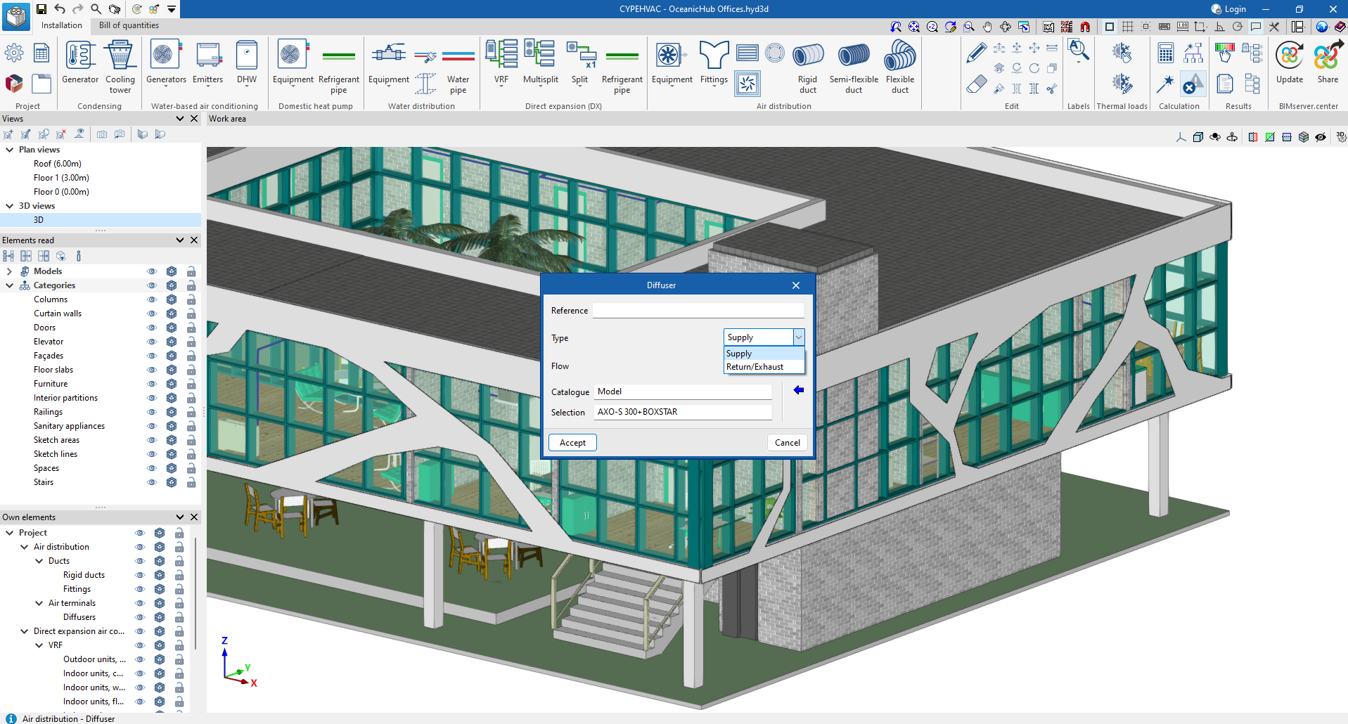
In version 2025.b, both supply and extract/return diffusers have been included in duct systems, so both supply and extract/return diffusers can now be inserted in CYPEHVAC.
Also, from the "Catalogue management" option, different diffuser manufacturer's catalogues can be downloaded. These new catalogues, which have been incorporated in this new version, contain a 3D view of the diffuser geometry, as well as the spigots and their design data.
Users can add these elements to the system by clicking on the "Diffuser" button in the "Air distribution" section.
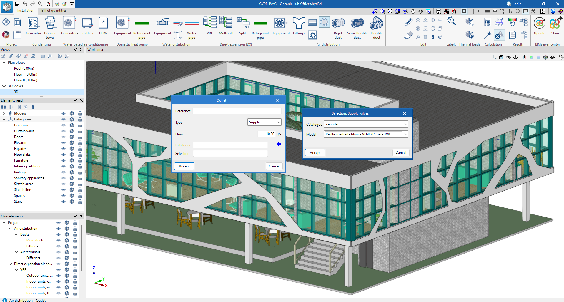
In this new version, the air terminals available in CYPEHVAC have been extended with the addition of supply and exhaust valves.
These elements are mainly used in controlled mechanical ventilation (CMV) systems.
Users can incorporate these elements into the system from the "Outlet" option in the "Air distribution" section, available once a manufacturer's catalogue has been downloaded via the "Catalogue management" button.
As of version 2025.b, CYPEHVAC can also be installed in Japanese. The languages in which this application can be installed are now as follows:
- Catalan
- Chinese
- English
- French
- German
- Italian
- Japanese
- Polish
- Portuguese
- Romanian
- Russian
- Spanish
- Turkish
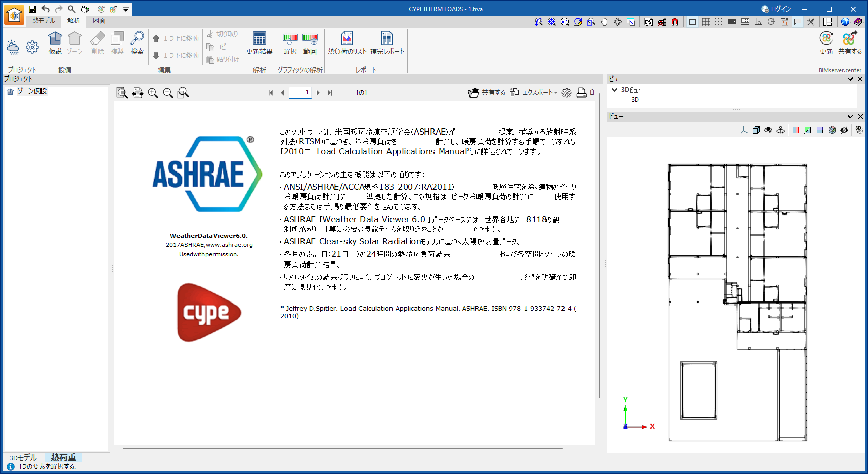
As of version 2025.b, CYPETHERM LOADS can also be installed in Japanese. The languages in which this application can be installed are now as follows:
- Catalan
- Chinese
- English
- French
- German
- Italian
- Japanese
- Polish
- Portuguese
- Portuguese for Brazil
- Romanian
- Russian
- Spanish
- Spanish for Argentina
- Spanish for Mexico
- Turkish
The "Type of design" field has been added to the "Columns" configuration panel with the following options:
- Detail all values. This option adds a row for each element that meets the conditions defined in the ‘Selection’. This is the default value and the behaviour that columns had in previous versions.
- Group. Groups the elements that have the same value for that column in a row.
- Match to minimum value. Obtains the minimum value of the parameter associated with the column for each of the selected elements in the row.
- Match to maximum value. Obtains the maximum value of the parameter associated with the column for each of the selected elements in the row.
- Calculate the total value. Adds the values of the parameter associated with the column for each of the selected elements in the row.
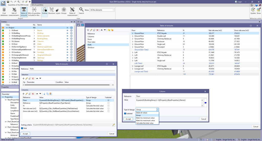
To generate subtotal lines, the “Subtotal” field has been added to the "Columns" configuration panel. When checked, a subtotal line is added to the table each time the column value changes.
In the “Table of amounts” configuration panel, the “Total” option has been added. When checked, a total line is added at the end of the table.
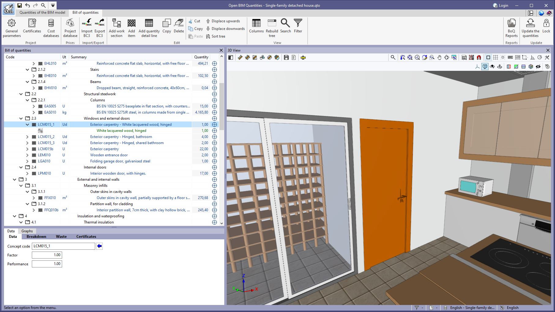
As of version 2025.b, Open BIM Quantities can use variables in the “References” of the items, in a similar way to other fields such as the “Detail line“ and “Tags“.

When changing the reference of the items, it is important to note that the codes must also be different.
Open BIM Quantities will automatically manage this when using “Update the quantities“ in the “Bill of quantities“ tab. The ‘Code’ indicated for the “Item“ in the “Rule of measurement“ will be used as the base code, adding a suffix for each different reference.
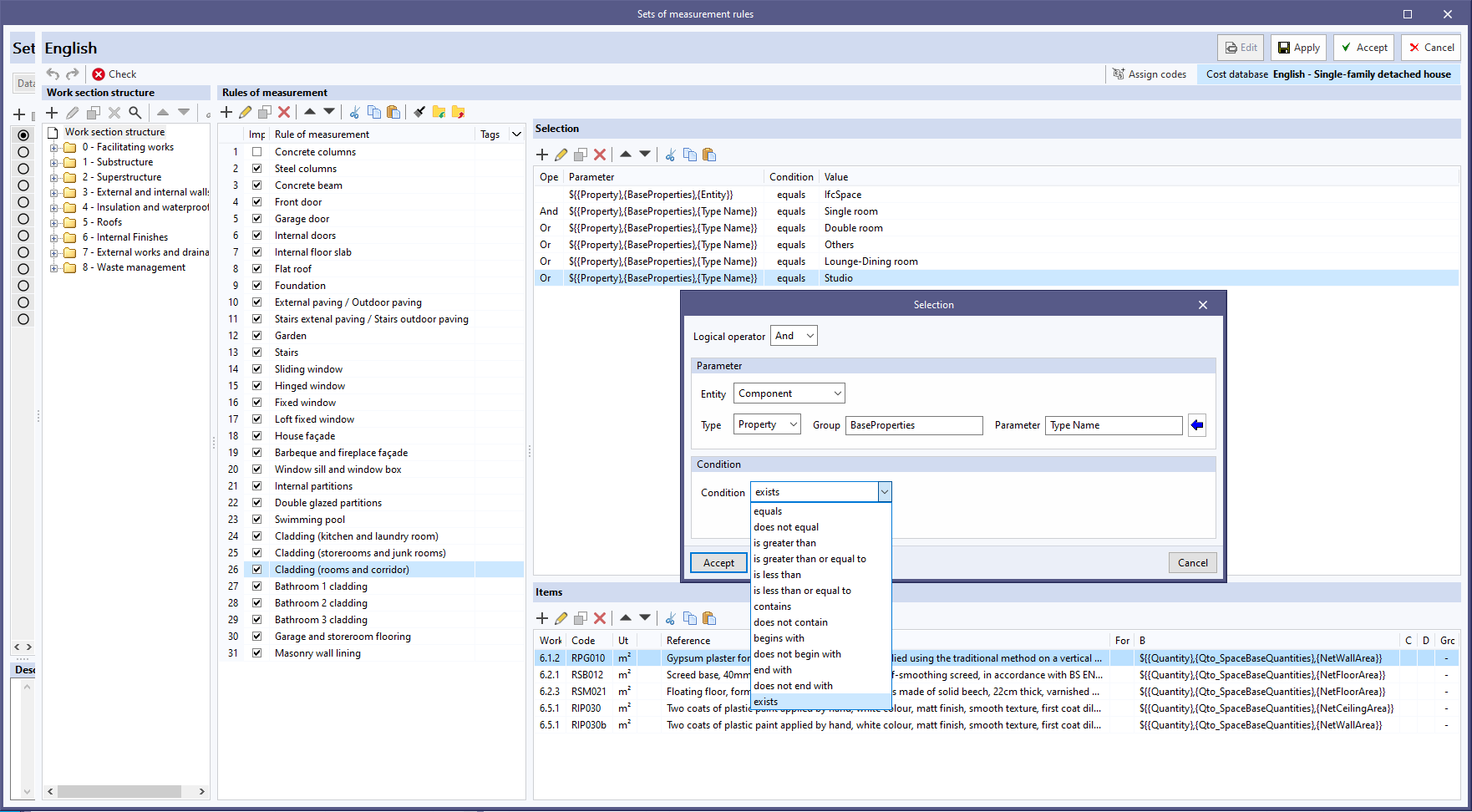
The “exists” condition has been added to the “Selection” setting of a “Rule of measurement”. By using this condition, only the “Parameter” is checked to ensure that it exists in the BIM model, without checking the content of the field.
Unlike the other available conditions, there is no need to indicate an associated “Value” when selecting “exists”.
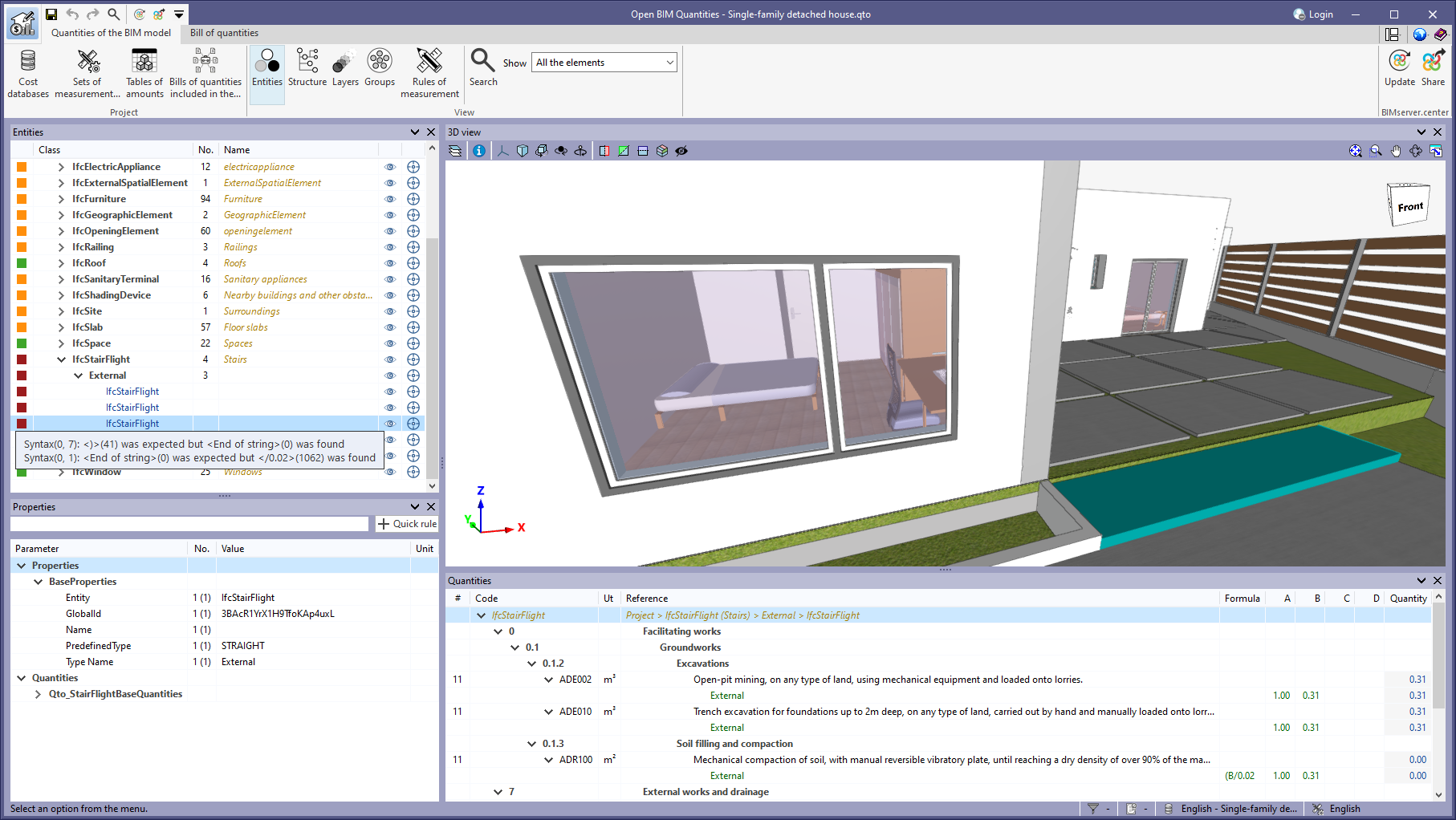
As of version 2025.b, Open BIM Quantities includes an automatic check of the syntax of the formulas used in the definition of the "Items" of a "Rule of measurement".
This check is carried out both in the configuration window of a "Set of measurement rules" and in the "Entities" tree of the "Quantities of the BIM model" tab.
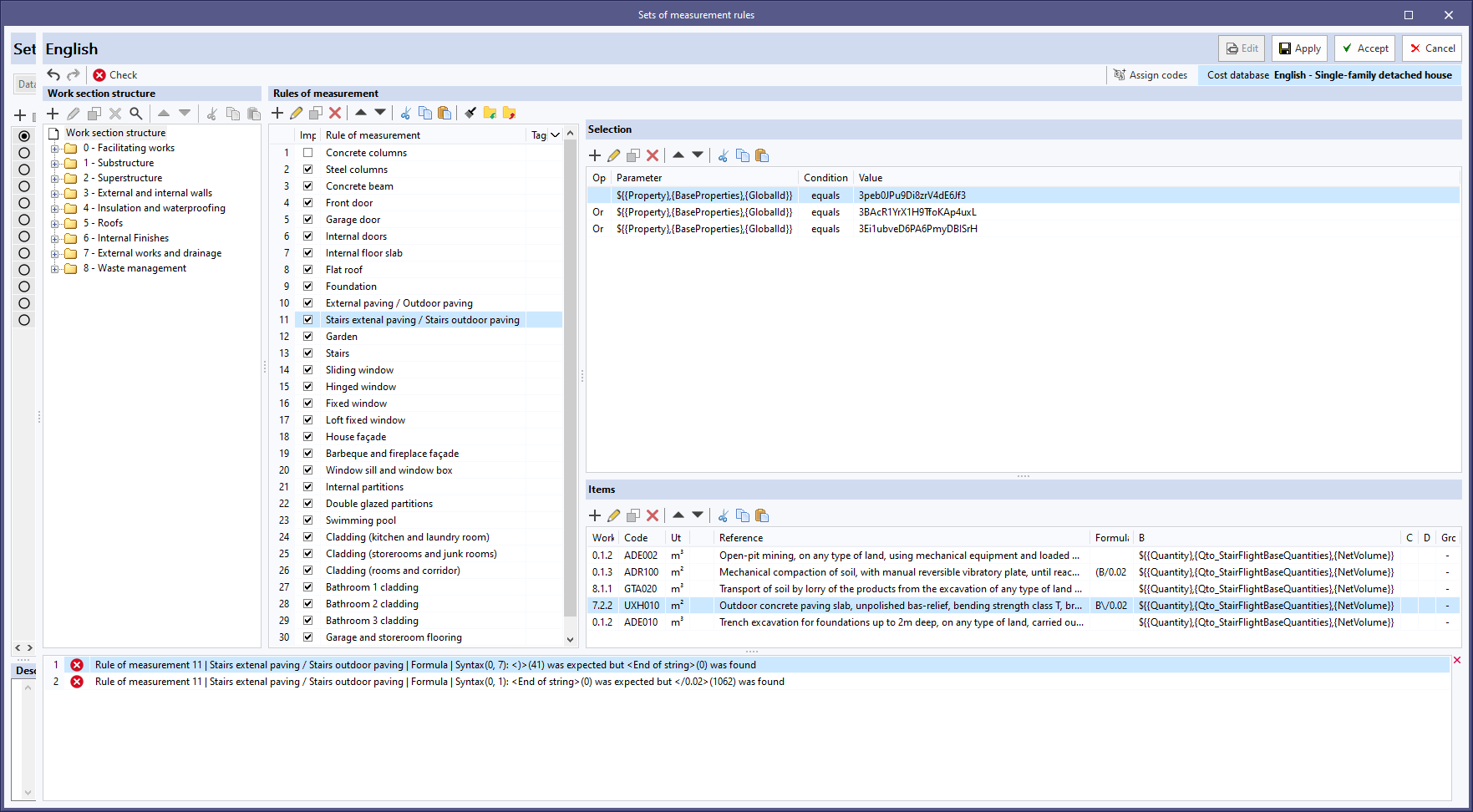
If a problem is detected in the syntax of a formula, the application displays a warning detailing the type of error.
This feature helps to quickly identify and correct errors in formulas, ensuring accuracy and consistency in BIM model quantity calculations.
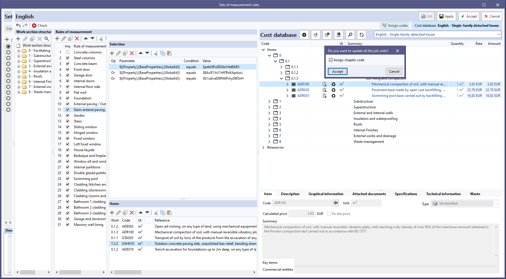
In version 2025.b, the “Sets of measurement rules” window includes a new option when using the ”Assign all” feature for a “Cost database”.
Users can now indicate whether they want to assign the cost database work section codes to the concepts of the rules of measurement.
When clicking the “Assign all” button, a window with the “Assign work section code” option appears. If this option is unchecked, the original work section codes from the set of measurement rules will be retained instead of assigning the new codes from the cost database.
This tool increases flexibility and control over the organisation and structure of work sections in projects, allowing users to maintain their own coding or adopt the cost database's coding according to their needs.
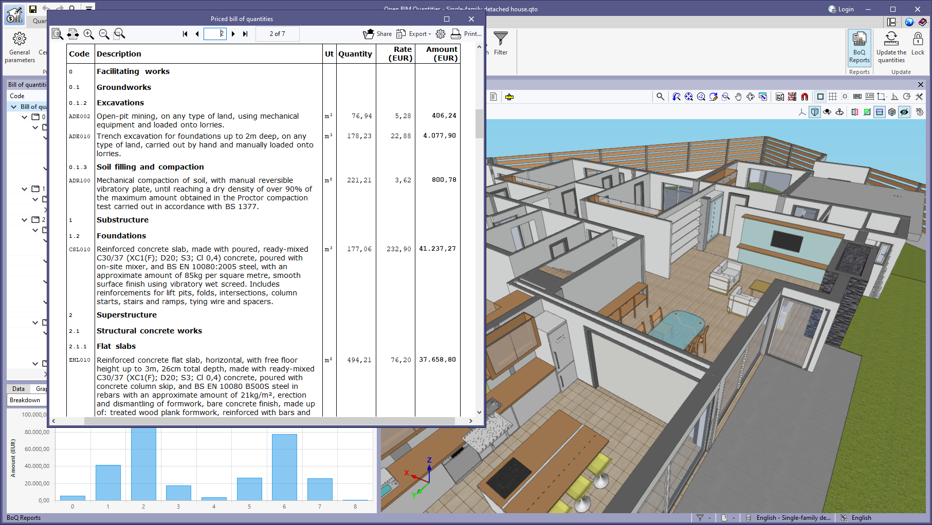
A new report called “Bill of quantities (Table)” has been added to the “BoQ Reports” available from the toolbar in the “Bill of quantities” tab.
This report includes all the concepts defined in the project in a table with the following columns:
- Code
- Description
- Unit
- Quantity
- Price
- Amount
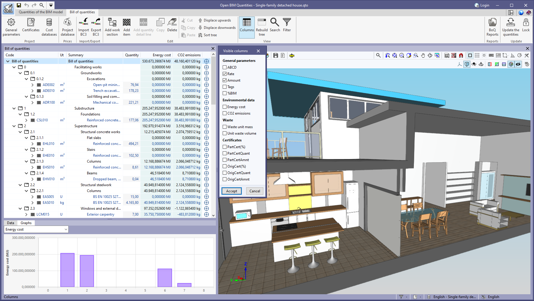
As of version 2025.b, Open BIM Quantities allows users to set the visibility of the “Price” and ”Amount” columns in several windows, including the ”Bill of quantities” table, the ”Project database” and the ”Cost databases”.
This configuration is done from the "Columns" option of the "Visualisation" group in the toolbar. Users can choose to hide or show these columns according to their needs, resulting in a more personalised interface focused on the relevant information for each type of project.
This feature is particularly useful for bills of quantities without prices.