Code implementation. ABNT NBR 6118 Projeto Junho 2013 (Brazil)
Projeto de estruturas de concreto - Procedimento.
This document is a project revision of the ABNT NBR 6118 2007 code, which is currently not in force, however it is foreseen that it will substitute the current standard.
It has been implemented in CYPECAD (including Strut3D) and Metal 3D.
Code implementation and improvements in its application. Eurocode 2 (EU, France, Portugal)
- Eurocode 2 (EU)
Design of concrete structures. EN 1992-1-1:2004/AC 2008 - Eurocode 2 (France)
Calcul des structures en béton. NF EN 1992-1-1:2005/NA: Mars 2007 - Eurocode 2 (Portugal)
Projecto de estruturasdebetão. NP EN 1992-1-1:2010/NA
These codes were already implemented as of previous versions. They were also included, in previous versions, in the group of codes which use CYPECAD’s advanced beam editor (which implies that as well as the advantages obtained from using this editor, detailed Ultimate Limit State reports and reinforcement tables can be automatically generated).
Now, as of the 2014.d version, when the selected concrete code is Eurocode 2 (EU), Eurocode 2 (France) or Eurocode 2 (Portugal), beams are edited using CYPECAD’s advanced beam editor. This implies important improvements in the application of these codes:
- Detailed U.L.S. and S.L.S. check reports for concrete beams (including check for failure due to torsion)
- U.L.S. and S.L.S. reports for steel beams
- Graphs and numerical values of the required and effective reinforcement areas
- Bar bending diagrams and reinforcement detailing configurations for frame drawings
- Design of dropped beams with a variable section
- And generally provides a graphical interface to edit the resistance elements of the frame (reinforcement, steel sections, lattices etc.) that is quick and easy to use.
More information can be found in the “Advanced beam editor” section on the webpage dedicated to concrete beams in CYPECAD .
If an analysis with seismic loads is carried out, each one of the Eurocodes; Eurocode 2 (EU), Eurocode 2 (France) and Eurocode 2 (Portugal), has a corresponding set of seismic codes with which it is compatible, and allow for CYPECAD’s advanced column and beam editors to be used, taking into account their capacity design criteria to design concrete beams and columns:
- Eurocode 2 (EU)
- Eurocode 8 (EU)
EN 1998-1. Eurocode 8: Design of structures for earthquake resistance. Part 1: General rules, seismic actions and rules for buildings.
- Eurocode 8 (France)
NF EN 1998-1/NA (2007) Eurocode 8: Calcul des structures pour leur résistance aux séismes.Partie 1 : Règles générales, actions sismiques et règles pour les bâtiments Annexe nationale à la NF EN 1998-1:2005.1
- Eurocode 8 (Portugal)
NP EN 1998-1 (2010). Eurocódigo 8 - Projecto de estruturas para resistência aos sismos. Parte 1: Regras gerais, acções sísmicas e regras para edifícios.
- Eurocode 8 (Belgium)
NBN-ENV 1998-1-1: 2002 NAD-E/N/F Eurocode 8: Conception et dimensionnement des structures pour la résistance au séisme. Partie 1-1: Règles générales. Actions sismiques et exigencies générales pour les structures
- PS 92 (France)
Règles de Construction Parasismique - Règles PS applicables aux bâtiments – PS 92.
- PS 92 (version révisée 2010) (France)
Règles de Construction Parasismique - Règles PS applicables aux bâtiments – PS 92 (version révisée 2010).
- RPA 99/v 2003 (Algeria)
Règles Parasismiques Algériennes RPA 99 / VERSION 2003.
- RPS 2000 (Morocco)
Règlement de Construction Parasismique.
- RPS 2011 (Morocco)
Règlement de Construction Parasismique (version révisée 2011).
- 1997 UBC (USA)
Uniform Building Code.
- 2009 IBC (USA)
International Building Code.
- Eurocode 8 (EU)
- Eurocode 2 (France)
- Eurocódigo 8 (Francia)
NF EN 1998-1/NA (2007) Eurocode 8 : Calcul des structures pour leur résistance aux séismes. Partie 1 : Règles générales, actions sismiques et règles pour les bâtiments Annexe nationale à la NF EN 1998-1:2005.1 - PS 92 (France)
Règles de Construction Parasismique - Règles PS applicables aux bâtiments – PS 92.
- PS 92 (version révisée 2010) (France)
Règles de Construction Parasismique - Règles PS applicables aux bâtiments – PS 92 (version révisée 2010).
- RPA 99/v 2003 (Algeria)
Règles Parasismiques Algériennes RPA 99 / VERSION 2003.
- RPS 2000 (Morocco)
Règlement de Construction Parasismique.
- RPS 2011 (Morocco)
Règlement de Construction Parasismique (version révisée 2011).
- 1997 UBC (USA)
Uniform Building Code.
- 2009 IBC (USA)
International Building Code.
- Eurocódigo 8 (Francia)
- Eurocódigo 2 (Portugal)
- Eurocode 8 (Portugal)
NP EN 1998-1 (2010). Eurocode 8 - Projecto de estruturas para resistência aos sismos
Parte 1: Regras gerais, acções sísmicas e regras para edifícios.
- 1997 UBC (USA)
Uniform Building Code.
- 2009 IBC (USA)
International Building Code.
- Eurocode 8 (Portugal)
The concrete and seismic codes that are available for the capacity design criteria for concrete columns and beams can be found in the “Capacity design criteria for seismic design of concrete columns and beams” section on the CYPECAD webpage.
More information can also be found in the “Design codes available for use with the Advanced beam editor” section on the Concrete beams webpage.
Reinforcement ductility criteria and capacity design criteria for seismic design for Eurocode 8 (EU, France, Portugal and Belgium)
When an analysis is carried out in CYPECAD using any of the indicated seismic design codes, combined with Eurocode 2 (EU), Eurocode 2 (France) and Eurocode 2 (Portugal), the program takes into account the reinforcement ductility criteria and the capacity design criteria for seismic design of the selected seismic code. These criteria are justified in the Ultimate Limit State reports generated by the advanced column and beam editors of CYPECAD.
More information on the combined use of these concrete and seismic codes can be found in the “Eurocode 2 (EU, France and Portugal)” section on this webpage.
Code implementation. ASCE 7-10 (USA)
Minimum Design Loads for Buildings and Other Structures.
Implemented in CYPECAD and Metal 3D.
Users can choose to CYPECAD carry out the dynamic analysis (modal spectral) or static analysis (equivalent lateral force) proposed by the ASCE 7-10 design code. The analysis method (dynamic or static) is selected using the Analysis method option within the dialogue box where seismic action is defined.
When the dynamic analysis (modal spectral) method is used, CYPECAD takes into account the correction due to base shear.
Code implementation and improvements in its application. NC 46:1999 (Cuba)
Construcciones sismo resistentes. Requisitos básicos para el diseño y construcción.
This code was already implemented in CYPECAD and Metal 3D as of previous versions using the dynamic analysis (modal spectral) method.
For this design code, the 2014.d version of CYPECAD includes:
- A static analysis method (equivalent lateral force)
The analysis method (dynamic or static) is selected using the Analysis method option within the dialogue box where seismic action is defined. - The correction due to base shear
This correction is applied to the seismic analysis using the dynamic analysis (modal spectral) method. To calculate the base shear using the NC 46:1999 code, CYPECAD has two options to indicate the value of the Fundamental period of the structure:
- In accordance with the code
- Specified by the user
More information on the correction due to base shear carried out by CYPECAD.
More information on how to establish the Fundamental period of the structure.
Code implementation and improvements in its application. NSR-10 (Colombia)
Reglamento Colombiano de Construcción Sismo Resistente (2010).
This code was already implemented in CYPECAD and Metal 3D as of previous versions. Now, for the 2014.d version, CYPECAD has two options to indicate the value of the Fundamental period of the structure (used to calculate the base shear):
- Based on the code (only possibility in previous versions)
- Specified by the user (implemented in the 2014.d version)
More information on how to establish the Fundamental period of the structure.
Eurocode 2 (EU, France and Portugal) in the advanced beam editor
The 2014.d version of CYPECAD allows users to use the advanced beam editor with the Eurocode 2 concrete codes (Eurocode 2 (EU), Eurocode 2 (France – which includes the National Application Document for France), Eurocode 2 (Portugal – which includes the National Application Document for Portugal)) combined with their corresponding seismic codes.
The ductility reinforcement criteria and capacity design criteria are also included and are indicated in the seismic codes that are compatible with Eurocode 2 (EU), Eurocode 2 (France) and Eurocode 2 (Portugal) as is indicated in section: “Eurocode 2 (EU, France and Portugal)” on this webpage, where more information can be found on the combined used of these concrete and seismic codes.
Reinforcement ductility criteria and capacity design criteria for seismic design for the combination of Eurocode 2 concrete code (EU, France and Portugal) and Eurocode 8 seismic code (EU, France, Portugal and Belgium)
The 2014.d version of CYPECAD includes the reinforcement ductility criteria and the capacity design criteria when they are combined in the same analysis with the Eurocode 2 concrete codes: Eurocode 2 (EU), Eurocode 2 (France), Eurocode 2 (Portugal) with their corresponding seismic codes.
More information on the combined use of these concrete and seismic design codes can be found in the Eurocode 2 (EU, France and Portugal) section on this webpage.
Fundamental period of the structure with user values for NSR10 (Columbia) and NC 46:1999 (Cuba)
When either of these codes is used in CYPECAD (NSR-10 (Columbia) and NC 46:1999 (Cuba)), there are two options to indicate the value of the Fundamental period of the structure (used to calculate the base shear):
- Based on the code (only possibility in previous versions)
- Specified by the user (implemented in the 2014.d version)
Both options can be selected in the Estimation of the fundamental period of the structure section in the Code for the calculation of seismic loading dialogue box (Job ˃ General data ˃ select “With seismic loading” in the “Loads” section ˃ select Columbia or Cuba as the country and the NSR-10 or NC 46:1999 codes respectively).
The value of the fundamental period of a building must be obtained based on the properties of its seismic resistant system, in the direction under consideration, in accordance with structural dynamics principles. Alternatively, most seismic codes have other procedures to estimate the fundamental period:
- In accordance with empirical formulas provided in their articles
- In accordance with other methods, as long as they are adequately sustained analytically or experimentally
The estimated fundamental period is applied in the static shear analysis at the base of the structure (base shear) to adjust the dynamic results to the minimum values prescribed in the codes, when the dynamic method is applied, and to generate the equivalent static lateral forces when the static method is applied.
The values indicated by the codes are limits that can be applied in the absence of more precise data. If users have fundamental period values, which are more adjusted to their structure (calculated using other methods or with software tools such as CYPECAD, which calculate the fundamental period of the structure in both directions – the values can be consulted after the analysis in the “Justification of seismic action” report: File ˃ Print > Job report) they can specify them using the option Specified by the user located in the Code for the calculation of seismic loading dialogue box.
Dimensions and effective mechanical steel areas of slabs for capacity checks of concrete columns and beams
CYPECAD, as of previous versions, takes into account the capacity design criteria of concrete beams and columns, for specific codes when undertaking the seismic analysis of the structure .
The geometric and mechanical properties of the columns and beams are automatically contemplated with the capacity checks (as of previous versions) as are, optionally, the properties of the floor slabs bearing on beams reaching a column (as of the 2014.d version).
To define the geometric and mechanical properties of the floor slabs, with regards to the capacity checks for concrete beams and columns, a new option has been implemented in the program: Assign data for the capacity check (Beam Definition tab > Beams/Walls).
The aforementioned option will only be visible if a seismic analysis is carried out with a design code which has the capacity check implemented for CYPECAD .
When this option is activated, a dialogue box appears where users can define the following data:
- Effective width (1)
- Effective width (2)
- Effective depth (3)
- Mechanical steel area of the top reinforcement
- Mechanical steel area of the bottom reinforcement
Users can assign them freely to any side or end of beams reaching columns. This way, slabs which have different geometric or mechanical properties at either side of the beam, or beams which only have the floor slab on one side can be contemplated.
To identify each of the sides and ends of the beam to which the data has been assigned for the capacity checks, the program displays small magenta triangles at these zones, which are displayed when the option Assign data for capacity check is selected. The triangles will be displayed in green at zones where the properties of the slab have not been assigned, in which case, the dimensions and steel areas of the slab will not intervene in the capacity checks for the concrete beams and columns.
Maximum size and nature of the aggregate
A new option has been implemented whereby users can define a different maximum aggregate size for each type of element: floor slabs, foundations, columns or walls (Job ˃ General data ˃ Aggregate properties in the reinforced concrete section).
Additionally, when the concrete EHE-08 (Spain) or ABNT NBR 6118 Projeto Junho 2013 (Brazil) codes are used, the nature of the aggregate can also be defined, with different values for floor slabs, foundations, columns or walls if users indicate it so. These design codes contain a correction coefficient of the longitudinal deformation module of the concrete, which depends on the nature of the aggregate used for its elaboration.
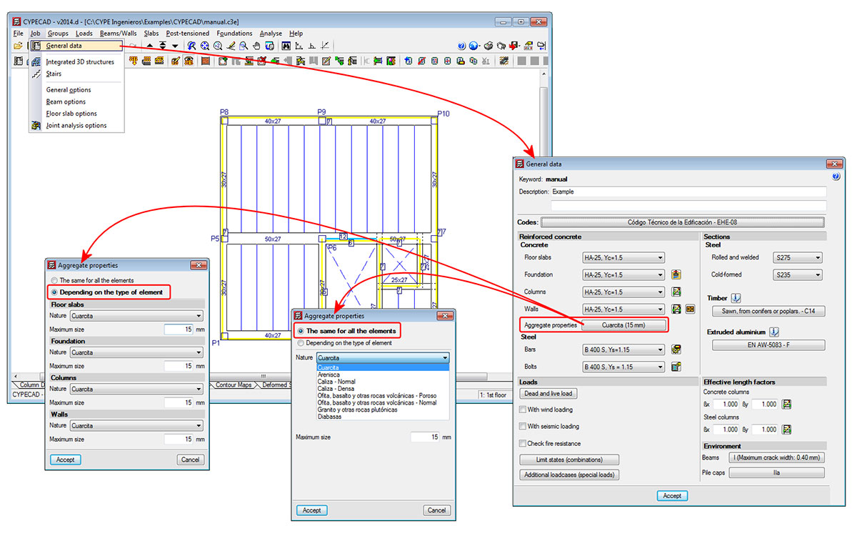
Using the EHE-08 code, the following aggregate nature types can be selected in accordance with that indicated in Table 39.6 (belonging to the comments of article “39.6. Módulo de deformación longitudinal del hormigón”):
- Cuarcita
- Arenisca
- Caliza normal
- Caliza densa
- Ofita basalto y otras rocas volcánicas - Poroso
- Ofita basalto y otras rocas volcánicas - Normal
- Granito y otras rocas plutónicas
- Diabasas
In the EHE-08 design code, the correction coefficient of the modulus of elasticity of the concrete is contained within the comments of the code, and so it is not obligatory for users to comply with it. When the nature of the aggregate is quartzite (cuarcita), the correction factor of the elasticity modulus has a value of 1, and this would be the option to be used if the reduction factor is not to be applied or, obviously, if this is the real nature of the aggregate that is used.
Using the ABNT NBR 6118 Projeto Junho 2013 code, the following aggregate natures can be selected as indicated in article “8.2.8. Módulo de elasticidade”:
- Basalto
- Diabásio
- Granito
- Gnaisse
- Calcário
- Arenito
Using the ABNT NBR 6118 Projeto Junho 2013 code, when a value of 1 is assigned to the correction coefficient of the modulus of elasticity of the concrete, it belongs to aggregates with “Granito” and “Gnaisse” natures.
Reduction of the concrete resistance of columns
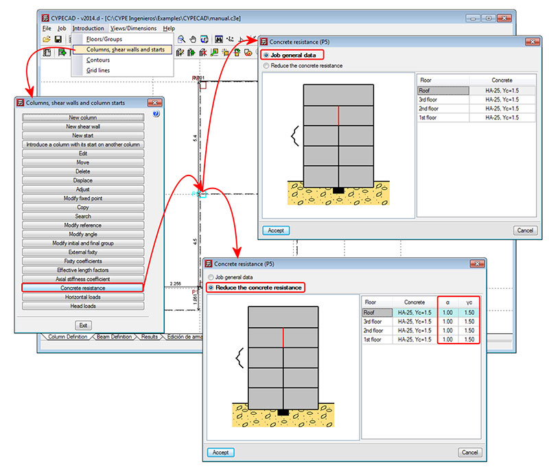
CYPECAD now allows users to apply reduction coefficients to the concrete resistance for each column span that is selected. This is possible with codes which can use the advanced column editor.
These coefficients are defined using the Concrete resistance option (Column Definition tab > Introduction > Columns, shear walls and starts). A column is selected using the left mouse button, after which a dialogue box appears on-screen where users can:
- If the Job general data option is activated, user can:
- View the type and general concrete reduction coefficients of the job
- If the option: Reduce the concrete resistance is activated, users can:
- View the type and general concrete reduction coefficients of the job
- Introduce concrete resistance reduction coefficients for each column span
- Modify the concrete resistance reduction coefficient at the required spans
This allows users to define the design resistance of the concrete for each column span if any tests have been carried out indicating the concrete has a low resistance.
Using the “Copy” option of the “Columns, shear walls and starts” dialogue box (Column Definition tab > Introduction > Columns, shear walls and starts), the program allows for the properties of a selected column to be copied to another that has already been introduced. Amongst the properties that can be copied are the reduction coefficients of the column selected as the model column, if the Concrete resistance option is activated in the dialogue box that appears when the column is selected.
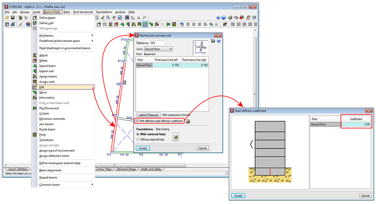
Axial stiffness coefficients for columns, shear walls and walls
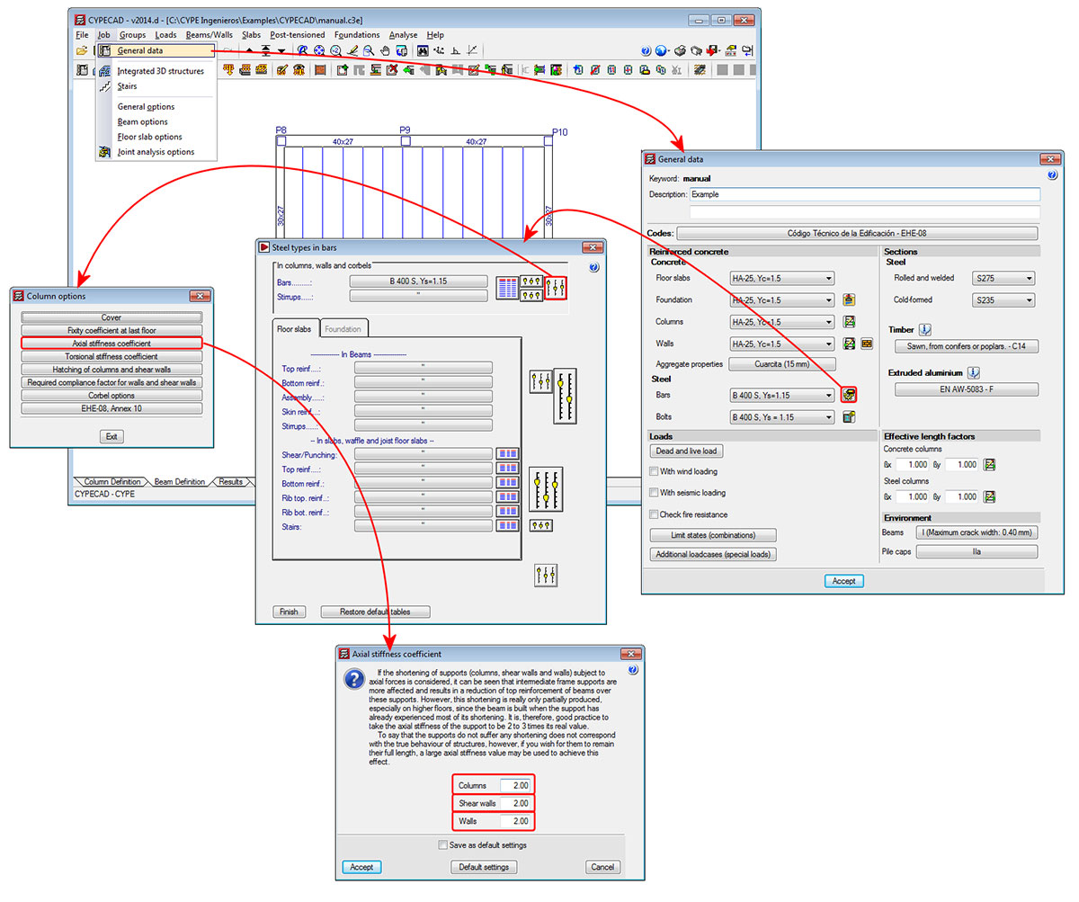
In previous versions, users could only introduce one axial stiffness coefficient for all the reinforced concrete columns, shear walls and walls of the job. As of the 2014.d version, three generic axial stiffness coefficients exist which can have different values:
- Axial stiffness coefficient for columns
- Axial stiffness coefficient for shear walls
- Axial stiffness coefficient for walls (reinforced concrete walls and plane stress walls )
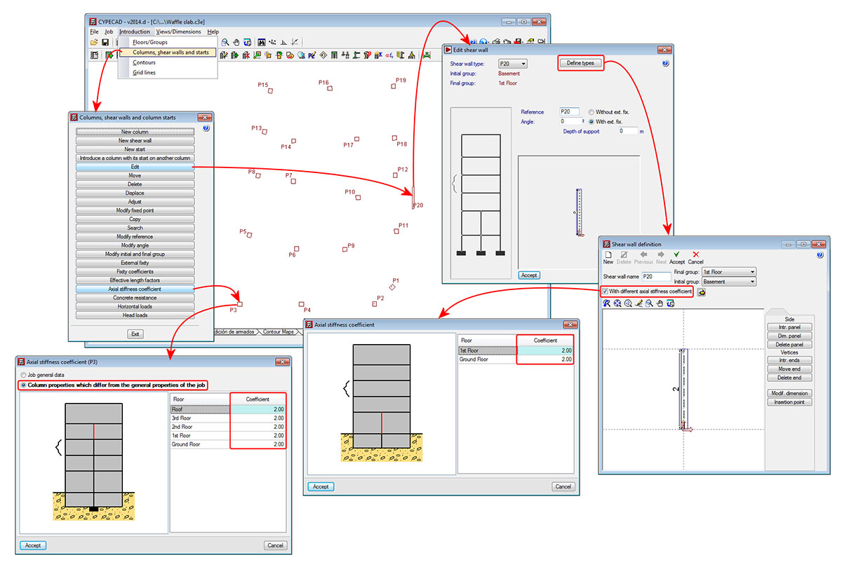
As well as the three generic axial stiffness coefficients, the 2014.d version of CYPECAD also allows for specific axial stiffness coefficients to be assigned to each column, shear wall, reinforced concrete wall or plane stress wall of the job.
An axial stiffness coefficient can be assigned to these elements with a different value at each span, following the process detailed below:
- For columns
The individual axial stiffness coefficients are assigned to each column (Column Definition tab > Introduction > Columns, shear walls and starts > Axial stiffness coefficient > select a column > select “Column properties which differ from the general properties of the job” > Introduce the axial stiffness coefficients for each floor). - For shear walls
The axial stiffness coefficients for shear walls are assigned to each shear wall type, which implies that all the shear walls of the same type that are introduced will have the axial stiffness coefficients for that type (Column Definition tab > Introduction > Columns, shear walls and starts > Edit > select a shear wall > Define types > select “With different axial stiffness coefficient” > introduce the axial stiffness coefficients for each floor). - For reinforced concrete walls and plane stress walls
The axial stiffness coefficients for walls are assigned to each wall span that is introduced in a single introduction step (Beam Definition tab > Beams/Walls > Edit > select a wall span > select “With different axial stiffness coefficient” > introduce the axial stiffness coefficients for each floor).
Reduction of reinforcement anchorage and splice lengths in columns, only for bars in tension
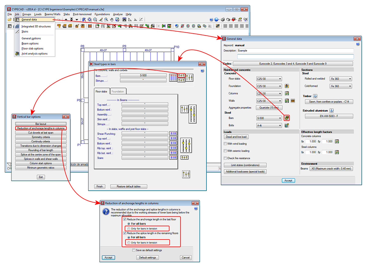
As of previous version, the anchorage length of the columns at the last floor and the splice length at other floors could be reduced. Now, with the 2014.d version, users can reduce the length of only bars that are in tension, in which case, a minimum resultant length for bars in tension has been established as Lb (basic anchorage length). This way, the anchorage lengths and splice lengths (if the reduction is also applied to floors below the last floor) will be more uniform.
To implement this new option, the “Reduction of anchorage lengths in columns” dialogue box now contains a new option: “Only for bars in tension”. This option can be activated separately for the last floor and for floors below the last floor.
Improvements in the work environment
Some of the buttons of the toolbar situated at the top of CYPECAD’s advanced beam editor (reinforcement edition, introduce openings, transverse sections), open floating windows that also contain other tools to edit the frames. As of the 2014.d version, these floating windows can be configured, offering the following options:
- Appearance of the floating windows
- Visibility of the floating windows (remain visible or hide automatically)
- Distribution of the tools of the floating windows around the work area
- Memorisation of the position, aspect and visibility of the floating windows
These improvements are the same as those that have been implemented for CYPECAD MEP and are explained in more detail on this webpage.
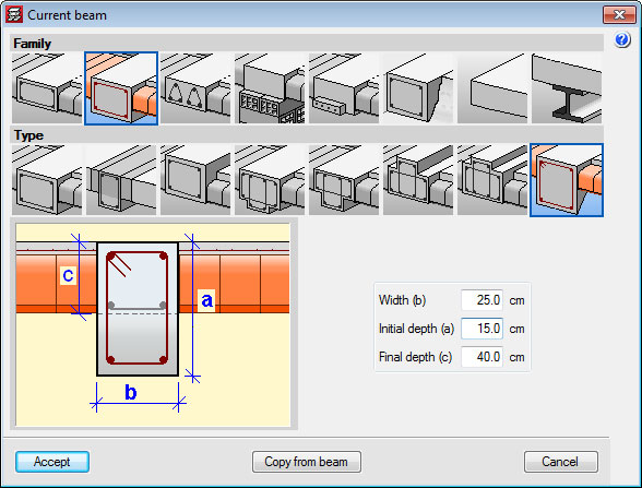
Dropped rectangular beams with variable sections
Dropped rectangular beams with variable sections can now be introduced in jobs analysed in accordance with a concrete code or seismic code (if a seismic analysis is being carried out) available for use with the advanced beam editor .
This possibility was already available with Continuous beams program. Now in CYPECAD, within the beam introduction dialogue box, a new type of beam has been added for which the program requests the width, initial depth and final depth.
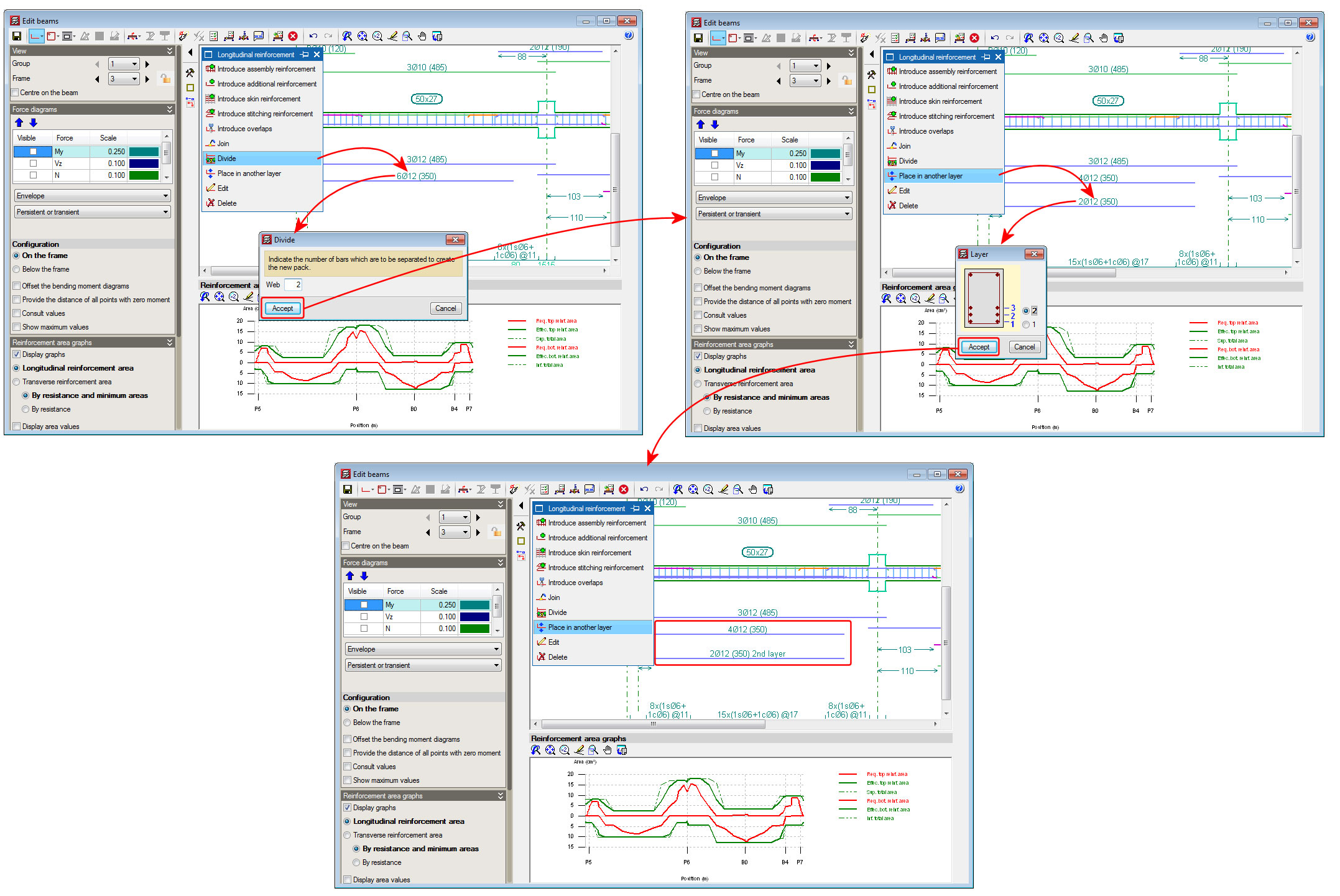
Divide a bar pack (change the layer of some of the bars of a pack)
A new option; Divide, has been implemented in the longitudinal reinforcement edition box of CYPECAD’s advanced beam editor. This option allows users to divide a pack of bars, in such a way that the number of bars indicated by users then becomes part of the other pack. By implementing this option, the one or two packs remaining after the division can be changed to other reinforcement layers.
In previous versions, to change bars belonging to a bar pack from one layer to another, user had to carry out two steps: reduce the number of bars of the packet and create another packet with the same number of bars that were removed (as well as having to indicate the same diameter, position and bar length). This procedure was not only a longer process but also increased the possibility of there being errors in the modifications.
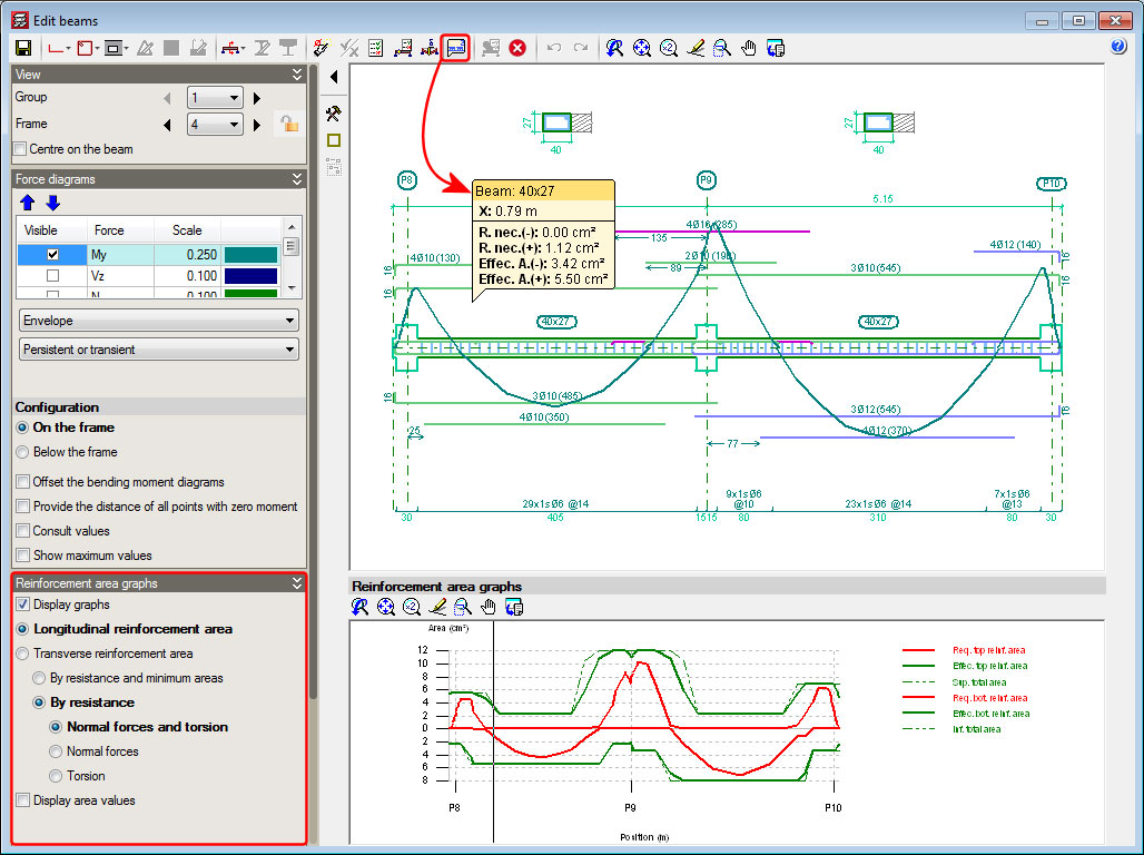
On-screen consultation of the required and effective areas of the reinforcement of a frame
A new option has been implemented: “Consult the required and effective areas” (![]() button) in the advanced beam editor of CYPECAD. When this option is selected, the program displays the required and effective areas of the reinforcement of the frame at the point of the longitudinal section where the cursor is positioned.
button) in the advanced beam editor of CYPECAD. When this option is selected, the program displays the required and effective areas of the reinforcement of the frame at the point of the longitudinal section where the cursor is positioned.
The information displayed moves with the cursor along the frame and displays the corresponding areas at the point where the cursor is positioned.
The data that is visualised on-screen corresponds to the type of reinforcement selected in the “Reinforcement area graphs” section in the left lateral menu of the advanced beam editor (longitudinal reinforcement area, transverse reinforcement area, resistance reinforcement and minimum steel areas...).
Representation of the floor slab in the transverse sections of beams in the frames drawing
A new option has been included in the 2014.d version of CYPECAD: “Draw the floor slabs at either side of the transverse sections of the beam”. This option is located in the configuration dialogue box for the frames drawing (see image). By activating this option, the floor slab will be displayed in the transverse sections of the frames in the frames drawing.
This option is only available with jobs analysed in accordance with a concrete code or seismic code (if a seismic analysis is being carried out) available for use with the advanced beam editor.
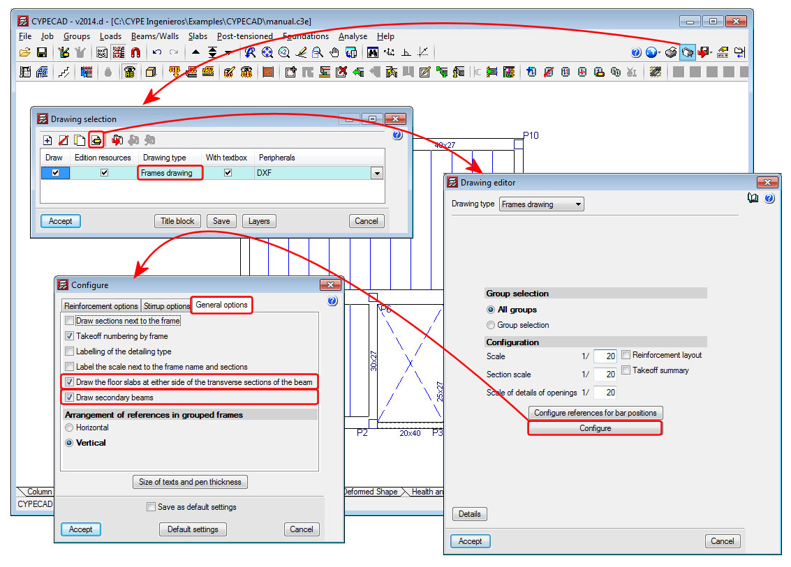
Drawing of secondary beams in the frames drawing
The 2014.d version of CYPECAP includes the option to “Draw secondary beams” in the configuration dialogue box for the frames drawing (see image). This option draws secondary beams (or not draw them if left inactivated) in the longitudinal section of the frames represented in the frames drawings. For CYPECAD, a secondary beam is that which divides which the longitudinal reinforcement of the beam.
This option will only be available with jobs analysed in accordance with a concrete code or seismic code (if a seismic analysis is being carried out) available for use with the advanced beam editor.