CYPETHERM ISO 10211 (new program)
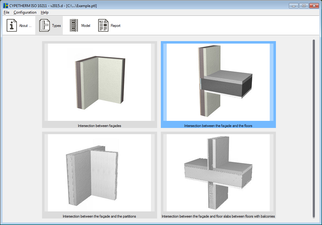
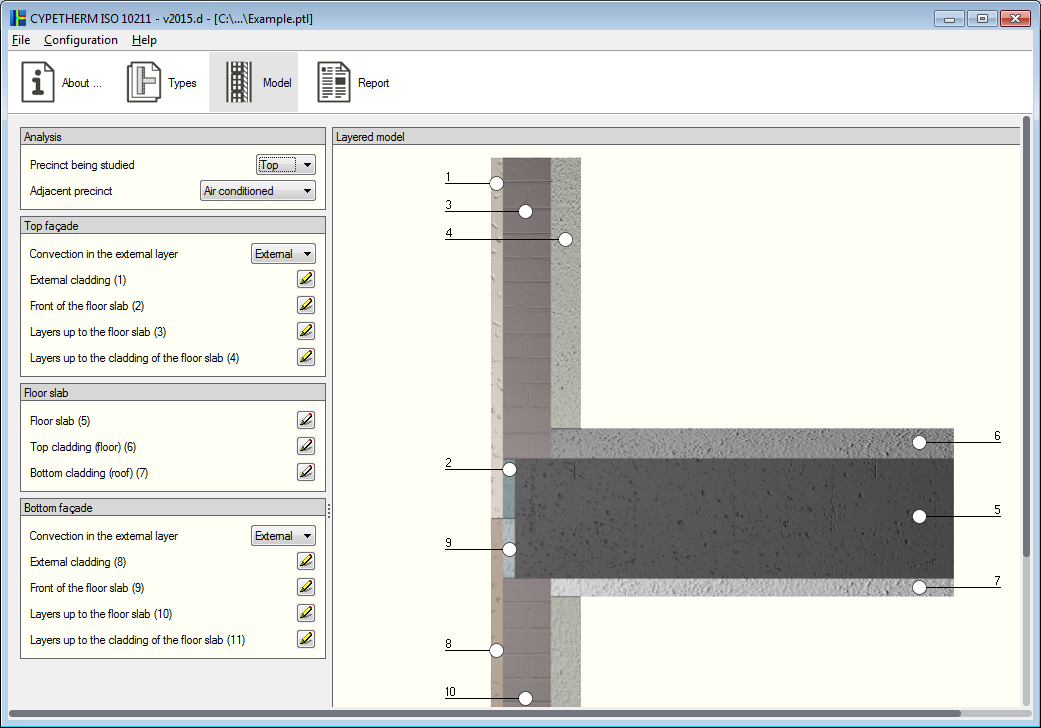
CYPETHERM ISO 10211 is an application conceived to determine the thermal transmittance of linear thermal bridges by solving and processing a finite element heat transfer analysis model, based on the UNE-EN ISO 10211 code. This application is located in the Building services group of the main CYPE program menu.
This program is part of an investigation to develop a software tool to integrate the numerical analysis of thermal bridges in the energy demand calculation of buildings, which is financed by the “Centro para el Desarrollo Tecnológico Industrial (CDTI)”, co-financed by the “European Regional Development Fund (ERDF)” and carried out in collaboration with the “Grupo de Ingeniería Energética” of the “Departamento de Sistemas Industriales” of Miguel Hernandez University in Elche (Alicante).
The main features of CYPETHERM ISO 10211 include:
- Analysis in accordance with EN ISO 10211
- Different thermal bridge models
- Libraries or material catalogues
- Analysis results
For users to be able to work with CYPETHERM ISO 10211, their user licence must include the “Numerical analysis of linear thermal bridges” permit.
More information can be found on the CYPETHERM ISO 10211 webpage.
Improved code application. CIRSOC 201 2005 (Argentina) and IS 456: 2000 (India)
- CIRSOC 201-2005 (Argentina)
Reglamento Argentino de Estructuras de Hormigón CIRSOC 201 (Julio 2005). - IS 456: 2000 (India)
Indian Standard. Plain and reinforced concrete code of practice (Fourth Revision).
These codes were already implemented in CYPECAD, CYPE 3D and other CYPE programs as of previous versions. Now, with the 2015.d version, the codes are implemented in “Punching shear verification” and therefore in the punching shear checks carried out by CYPECAD, in accordance with code criteria. This check was implemented in CYPECAD in the 2015.a version and, since then, coexists with the tangential stress check.
Code implementation. CIRSOC 103-2013 (Argentina)
Reglamento INPRES - CIRSOC 103 - Parte I - 2013. Normas Argentinas para Construcción Sismorresistente.
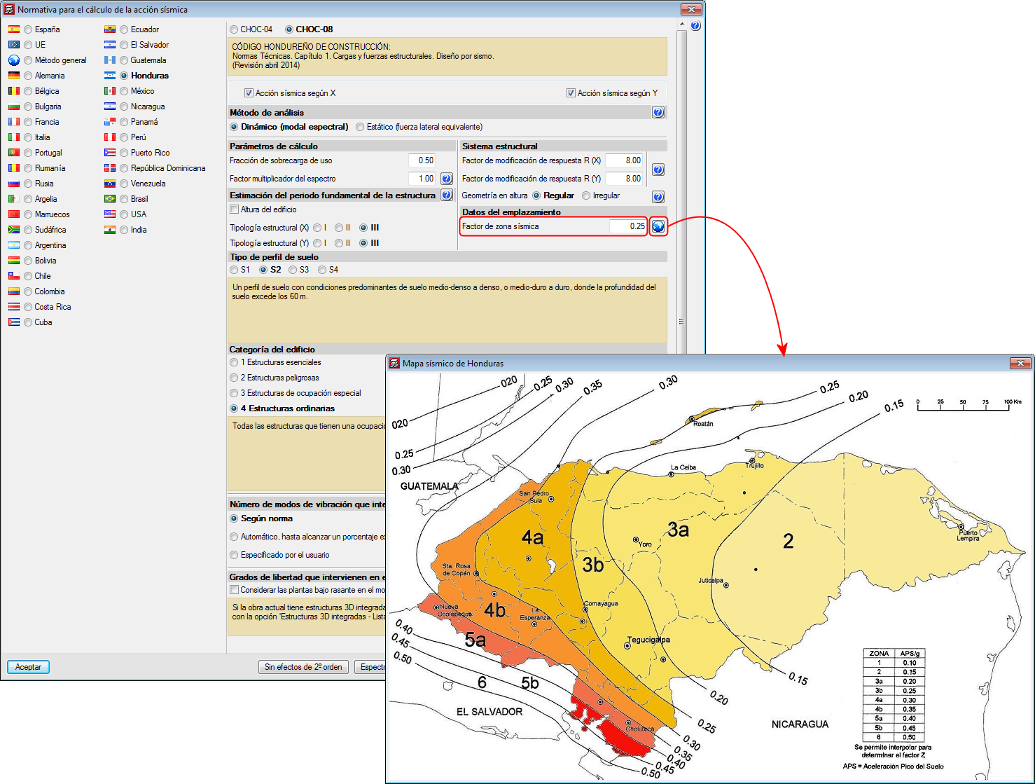
Improved code application. CHOC-08 (Honduras)
Código Hondureño de la Construcción. Normas Técnicas. Capítulo 1. Cargas y fuerzas estructurales. Diseño por Sismo
This code was already implemented in CYPECAD and CYPE 3D in previous versions. Now, with the 2015.d version, the new seismic map (which displays zones 3, 4 and 5) has been implemented and values between 0.10 and 0.60 can be introduced for the “Factor de zona sísmica” (Seismic zone factor).
Code implementation. NTC 1997 (Mexico – Guadalajara)
Normas Técnicas Complementarias para Diseño por Sismo para Guadalajara 1997.
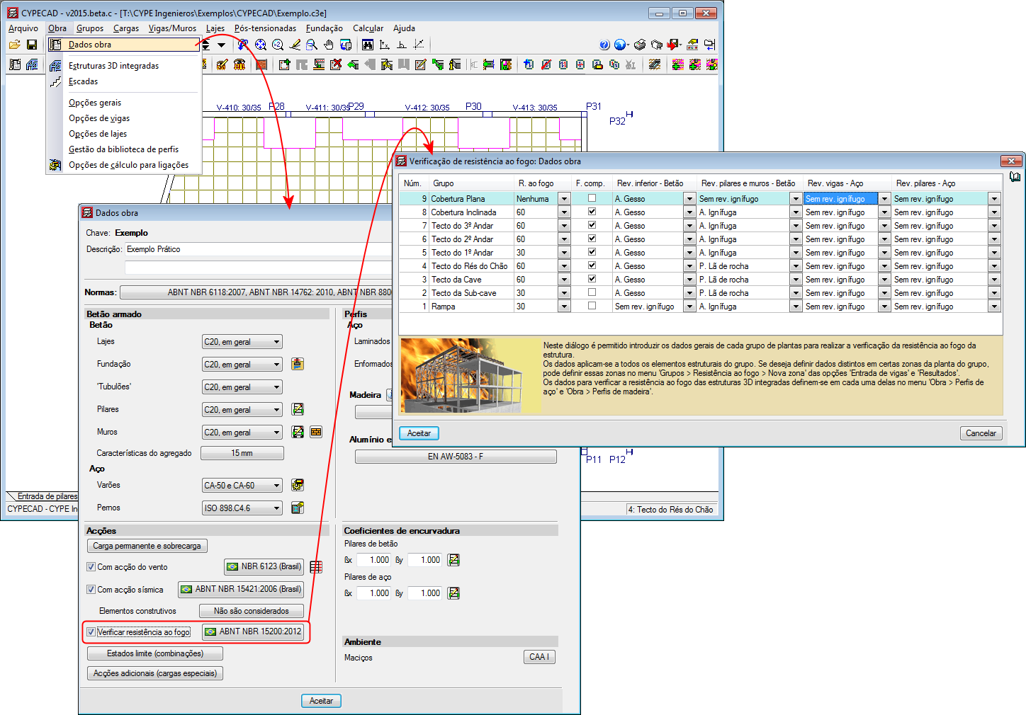
Code implementation. ABNT NBR 15200:2012 (Brazil)
Projeto de estruturas de concreto en situação de incêndio.
Implemented in the “Fire resistance check” module and checks the fire resistance and designs the protective coatings for beams, floor slabs, columns, concrete shear walls and walls using the tabular method defined in this code.
With this code, the “Fire resistance check” module carries out the following checks and designs:
- For the indicated structural elements for which a protective coating can be defined, the program designs the minimum thickness of the protective coating so that the requirements of the applied code are met.
- For the indicated structural elements for which a protective coating can be defined, the program checks the element with the assigned fire resistance data.
- If a coating is assigned to a structural element and the program verifies it is not needed to meet the requirements stated in the corresponding code, the program will indicate the coating of the structural element is not necessary, and so the minimum thickness of the coating will be applied for construction reasons.
Users must have the “Fire resistance check” module to be able to carry out these checks, as well as the corresponding aforementioned structural elements.
The fire resistance check in CYPECAD is activated in the “General data” dialogue box (Job > General data). Upon activating it, a dialogue box opens where users can define the required resistance, the compartmentation of the floors (with or without compartmentation) and the coatings of the construction elements. If users wish to use the “ABNT NBR 15200:2012” fire resistance code, the “ABNT NBR 6118:2014” or “ABNT NBR 6118:2007” concrete code must be selected in CYPECAD.
The corresponding Brazilian code required to carry out the fire resistance checks of steel beams and columns in CYPECAD and steel sections in CYPE 3D will be implemented in upcoming versions.
Code implementation and improvements in its application in CYPECAD
Improvements of the codes indicated below have been implemented or included in the application. Detailed information can be found in the previous sections:
- Concrete code
- CIRSOC 201 2005 (Argentina) and IS 456: 20000 (India)
- Code regarding loads on structures. Seismic loads
- CIRSOC 103-2013 (Argentina)
- CHOC-08 (Honduras)
- NTC 1997 (Mexico – Guadalajara)
- Fire safety. Fire resistance of the structure
- ABNT NBR 15200:2012 (Brazil)
Punching shear verification
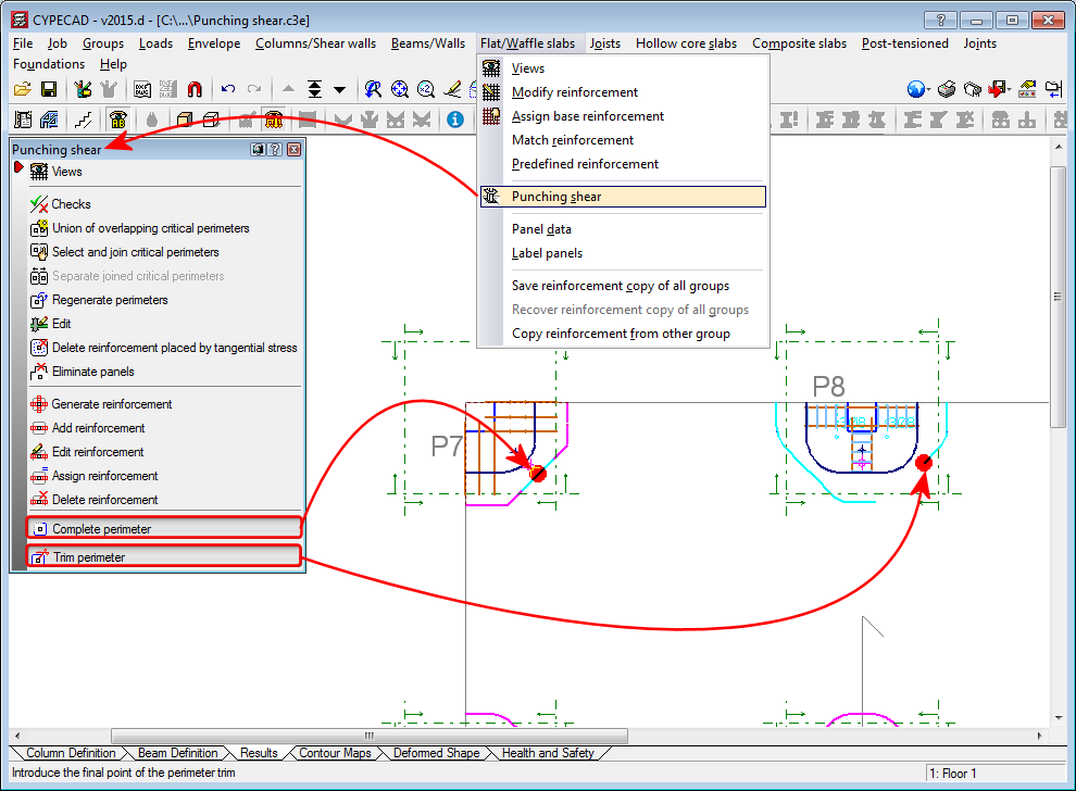
Complete and trim punching shear perimeter
Two options have been implemented which allow users to modify the punching shear perimeter calculated by the program (Results > Flat/Waffle slabs > Punching shear):
- Complete perimeter
Allows users to draw the punching shear perimeter on zones at which it has been trimmed by the analysis or manually. - Trim perimeter
Allows users to trim the punching shear perimeter of a column.
Users can use the “Regenerate perimeters” option (Results > Flat/Waffle slabs > Punching shear) to eliminate any modifications carried out on the punching shear perimeters.
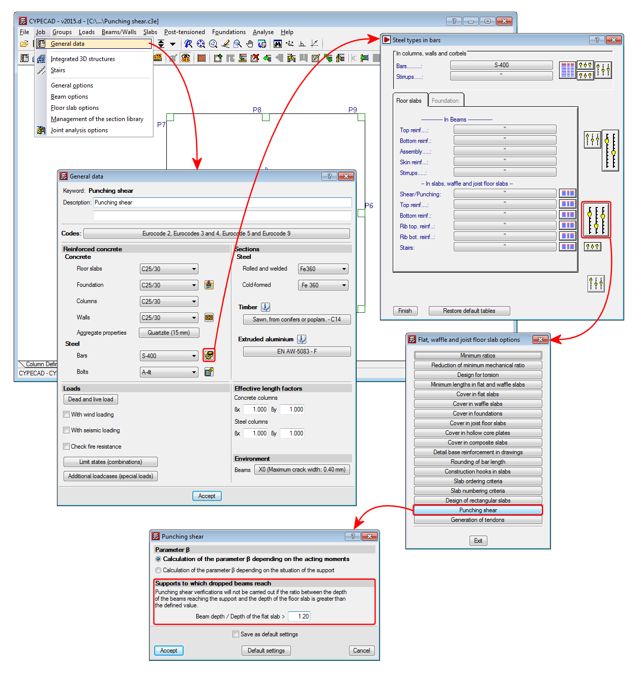
Punching shear check at supports with adjacent dropped beams
The option “Supports to which dropped beams reach” has been implemented (Job > General data > By position button > Slab options > Punching shear) which does not allow the punching shear check to take place at a support if the ratio between the depth of the dropped beams adjacent to the support and the depth of the slab is greater than the value defined in this option. The default value for this ratio is 1.20.
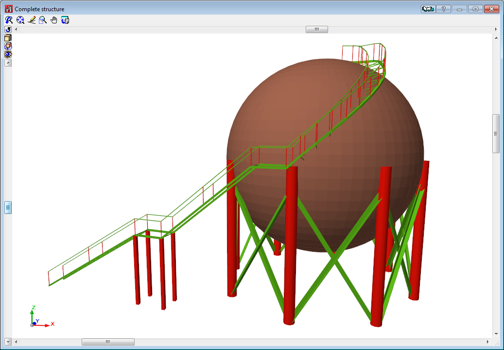
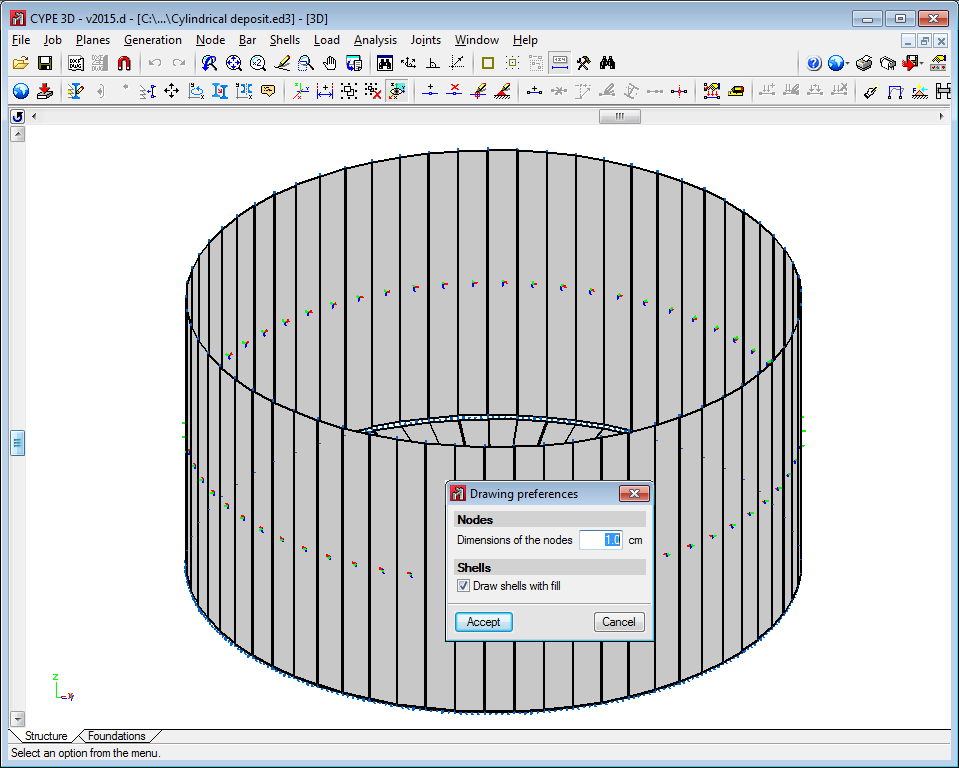
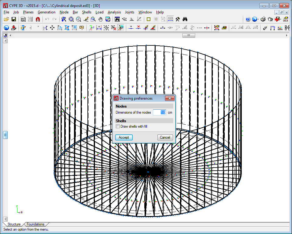
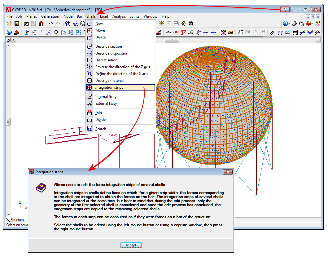
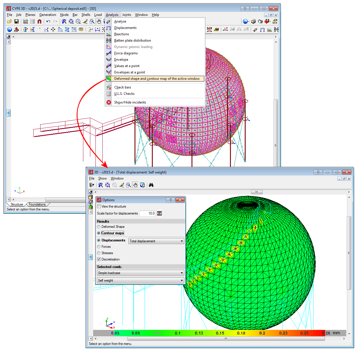
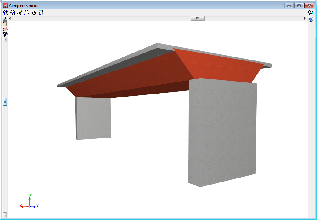
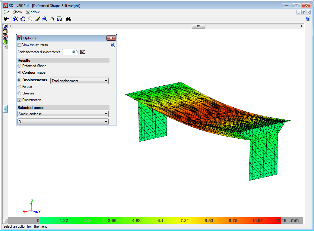
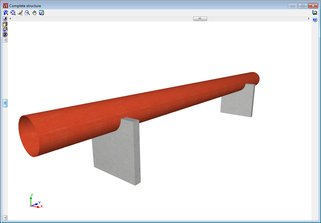
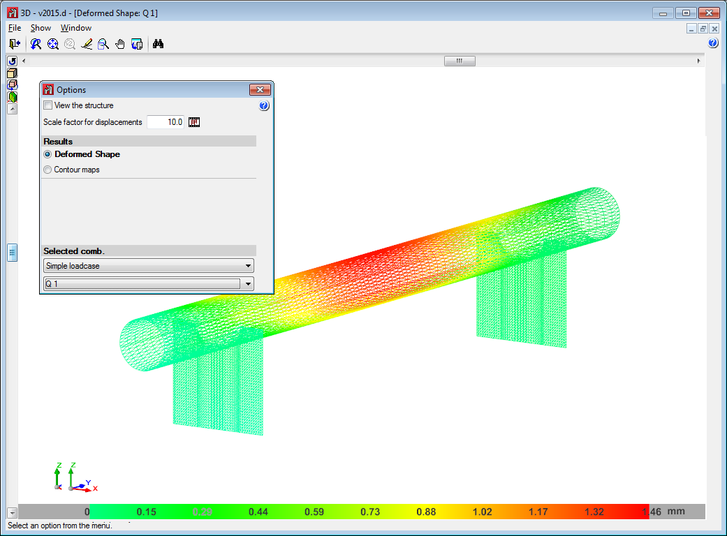
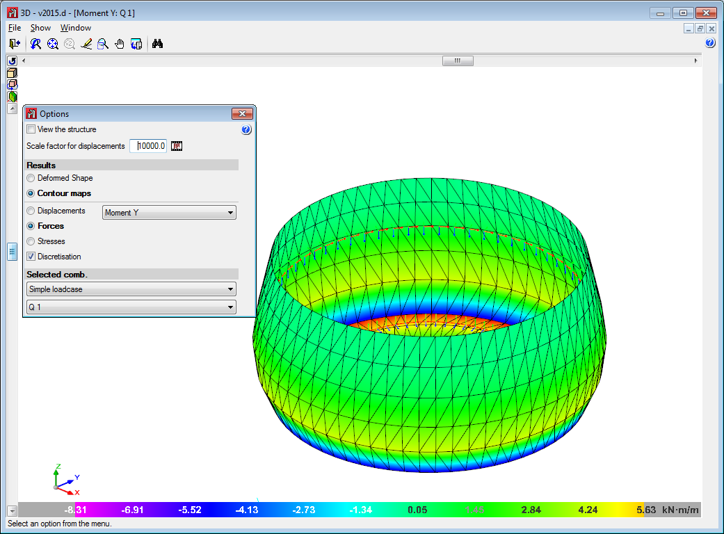
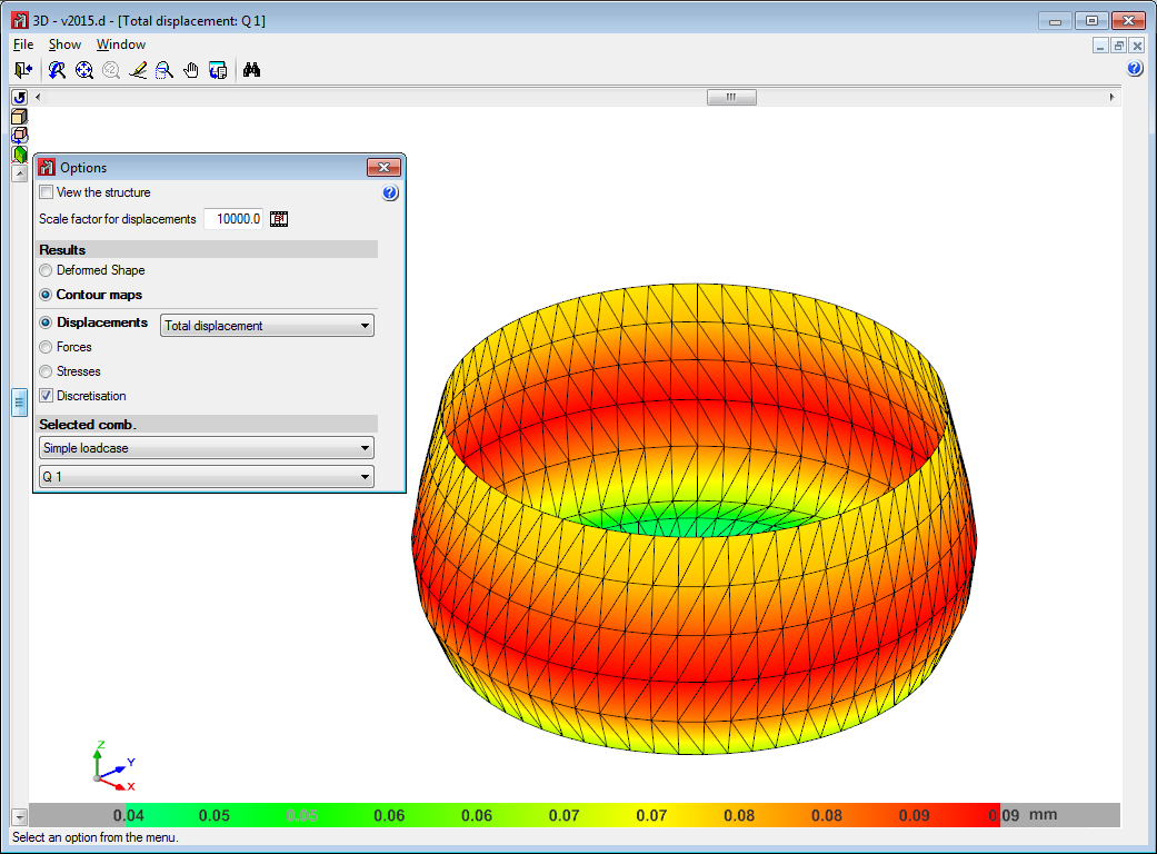
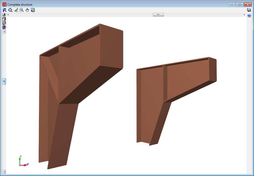
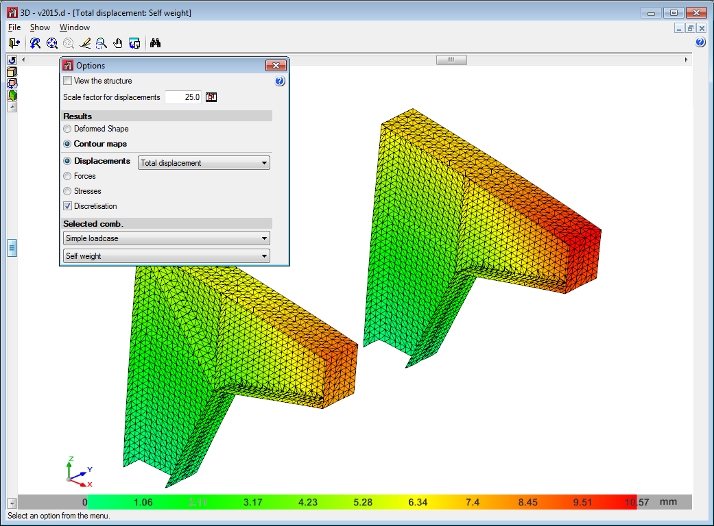
Shells in CYPE 3D
The 2015.d version of CYPE 3D allows users to define shells. Shells are flat two-dimensional elements with constant thickness and without openings, whose perimeter is defined by a polygon.
Shells are introduced in the global stiffness matrix of the structure using a three-dimensional finite element model composed of six-node (quadratic) triangular flat shells. The type of element used is based on the overlap of two locally decoupled elements: one provides the axial stiffness (membrane forces) and the other the bending stiffness (panel forces).
The following properties can be defined for each shell:
- Thickness and subgrade modulus
In the local Z axis direction - Material
Concrete, rolled steel, cold-formed steel, aluminium and generic material (by specifying the modulus of elasticity and Poisson coefficient). - Position
With respect to the introduction plane - Discretisation
The density of the mesh can be controlled by defining the maximum size of the triangle in the local x and y axes. - Direction of the axes
- Internal fixity
Internal fixity between the edges and other elements of the structure. - External fixity
It is also possible to define the external fixity of the edges, but in this case, the fixity is applied to all the shells sharing that edge. The possible external fixity configurations are the same as those available for the nodes of CYPE 3D. - Integration strips
Integration strips in shells define lines on which, for a given strip width, the forces corresponding to the shell are integrated to obtain the bar forces.
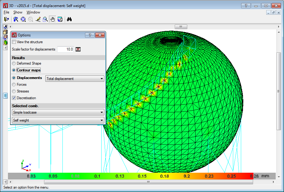
The program contains an option which users can use to view the shells in 3D. They can be viewed filled in or simply their outline can be displayed. This can be indicated in the drawing preferences option in the Job menu.
To be able to use shells in CYPE 3D, users must have the permits required to use CYPE 3D.
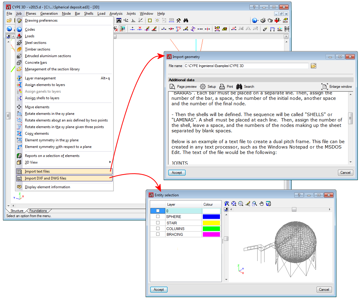
Below are some examples of structures created with shells in CYPE 3D:
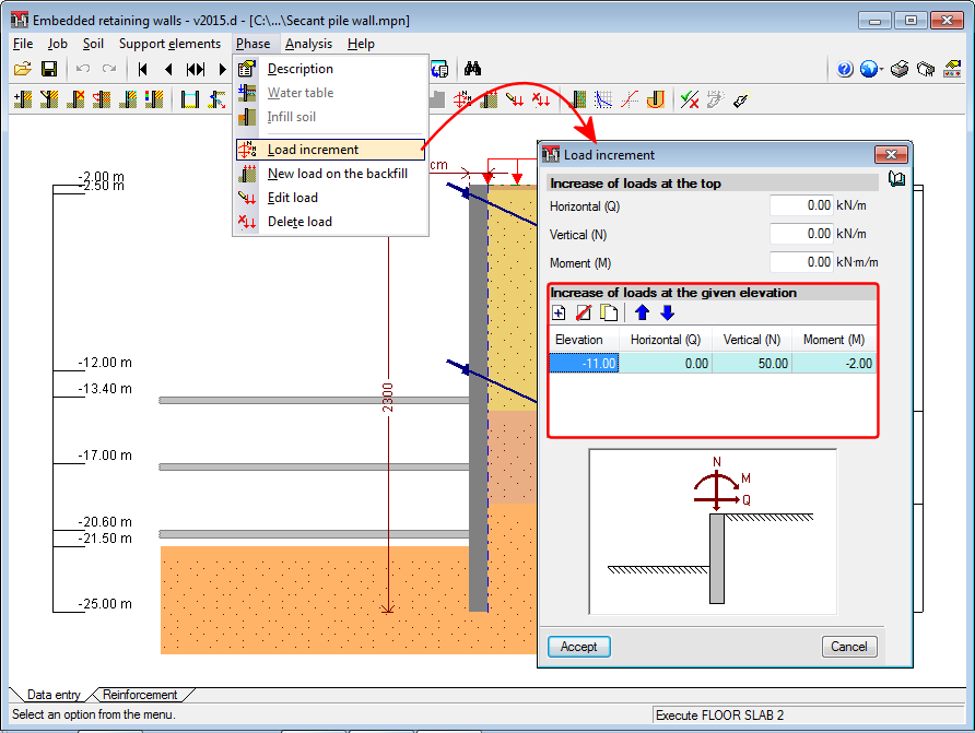
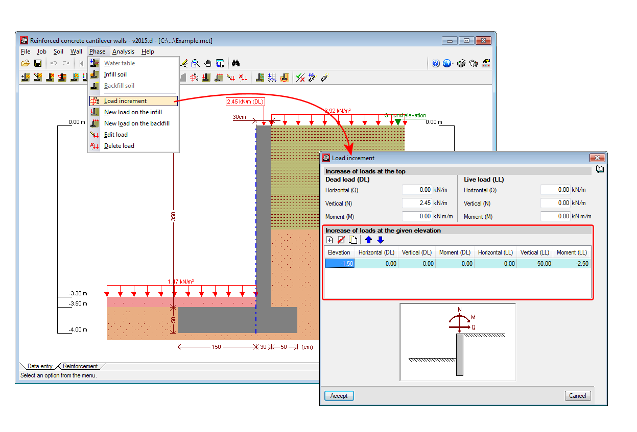
Increase loads at a specific elevation
As of previous versions, users could introduce loads along the top of the wall (horizontal -Q-, vertical -N- and moment -M). Now as of the 2015.d version, these load increments can also be specified at a specific elevation of the wall. The loads can be introduced at any phase and the program automatically and simultaneously takes them into account in all the following phases. In the case of Cantilever walls, the load can be defined as a permanent or live load, as occurs with the loads applied along the top of the wall.
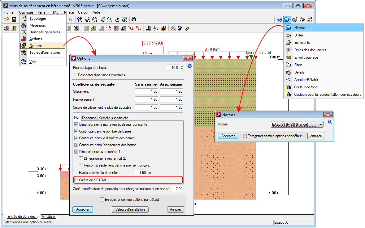
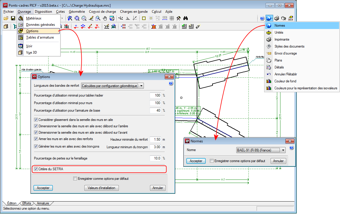
Deactivate SETRA criteria for the French BAEL-91 code
When jobs are analysed in Cantilever walls and Box culverts in accordance with the French BAEL-91 code, the SETRA criteria (critère du SETRA “Les ouvrages de soutènement: Guide de conception générale”) can be deactivated.
Code implementation
As indicated in the previous sections, the “CIRSOC 201 2005” code (Argentina) and “IS 456: 2000” code (India) have been implemented in “Punching shear verification” and CYPECAD (for punching shear check in accordance with code criteria).
Change of program name
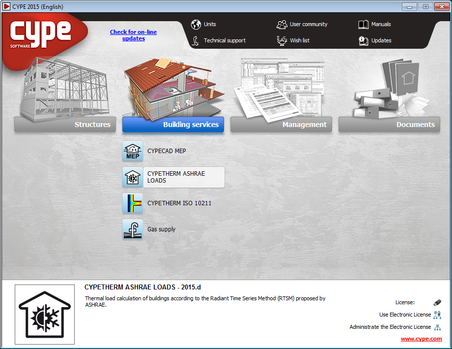
As of the 2015.d version, the program is called CYPETHERM ASHRAE LOADS, becoming a part of the CYPETHERM program group of CYPE.
Availability in other languages
In the 2015.b version, the program, CYPETHERM LOADS was implemented. This application was conceived to analyse the thermal loads of buildings in accordance with the Radiant Time Series Method (RTSM) proposed by ASHRAE.
The first version of CYPETHERM LOADS was only available in Spanish and in English. Now, with the 2015.d version, the program is also available in Catalan, French, Italian and Portuguese. Furthermore, the name of the program has changed to CYPETHERM ASHRAE LOADS for all languages.
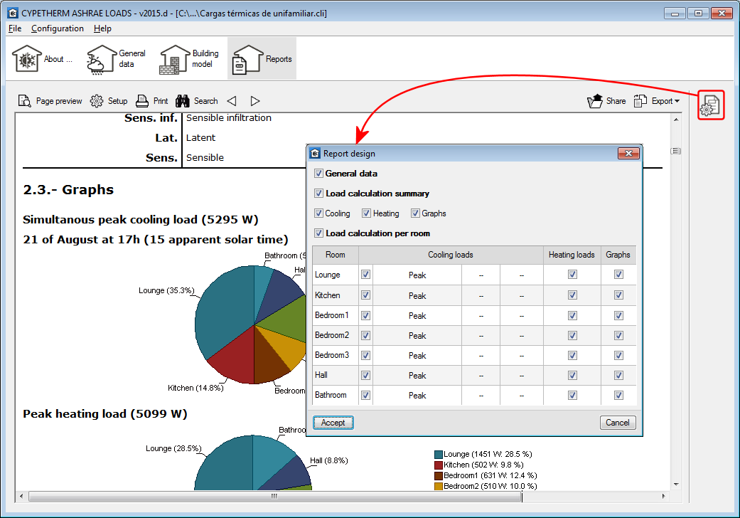
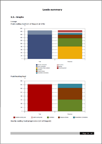
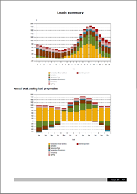
Report configuration
The 2015.d version of the program includes a helpful tool to configure the results report, which allows, amongst other things, to include the different sections that are available as well as select the type of load of each precinct to be included, even the specific moment for the cooling thermal loads.
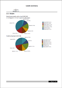
Report improvements
The reports have been improved and different graphs have been included to offer a global view of the results.
Gas supply in English
The program “Gas Supply” is installed when the software is installed in English. This program can be found in the Building services menu. This program was already available in Catalan, Spanish for Spain, Spanish for Argentina and Spanish for Mexico.
Gas supply is a program created to analyse, design, size and check network, branched and mixed gas networks.