

Integrated 3D Structures
General aspects of the 3D integrated structures
CYPECAD and CYPE 3D are connected by means of "Integrated 3D Structures" that allow CYPECAD to include a structure in CYPECAD with the same design assumptions that CYPE 3D has.
An integrated 3D structure is a steel, aluminium or timber structure made up of nodes and bars with six degrees of freedom that is connected and bonded to the main building structure managed by CYPECAD. Therefore, the deformations of the CYPECAD structure will affect the transmission of forces to the integrated 3D structure.
It must be noted that the construction elements introduced into CYPECAD jobs do not have six degrees of freedom, as CYPECAD considers the hypothesis of non-deformability at ground level. This is different for integrated 3D structures, as the links between their nodes are defined in the same way as in CYPE 3D.
CYPECAD's Integrated 3D Structures is not a module per se, in order to define them, users simply require permissions for using CYPECAD and CYPE 3D in the user license.
Several 3D structures can be added to the same CYPECAD project.

Connections of the integrated 3D structures with CYPECAD
An integrated 3D structure is linked to the CYPECAD structure by means of connections, which can be placed on the following CYPECAD elements:
- Columns
- Column starts (on which footing or pile caps can then be defined)
- Beams
- Flat or waffle slabs
- Floor slabs and foundation beams
- Snaps of elements from a DXF or DWG file (even if these are not initially placed on any of the above elements)
The connections of a single integrated 3D structure may be located on different floors of the main CYPECAD structure and may also have different elevation changes depending on the elevation of the floor on which they are located.

Ways of introducing integrated 3D structures
CYPECAD allows an integrated 3D structure to be introduced by creating it directly in CYPECAD or importing it from CYPE 3D.
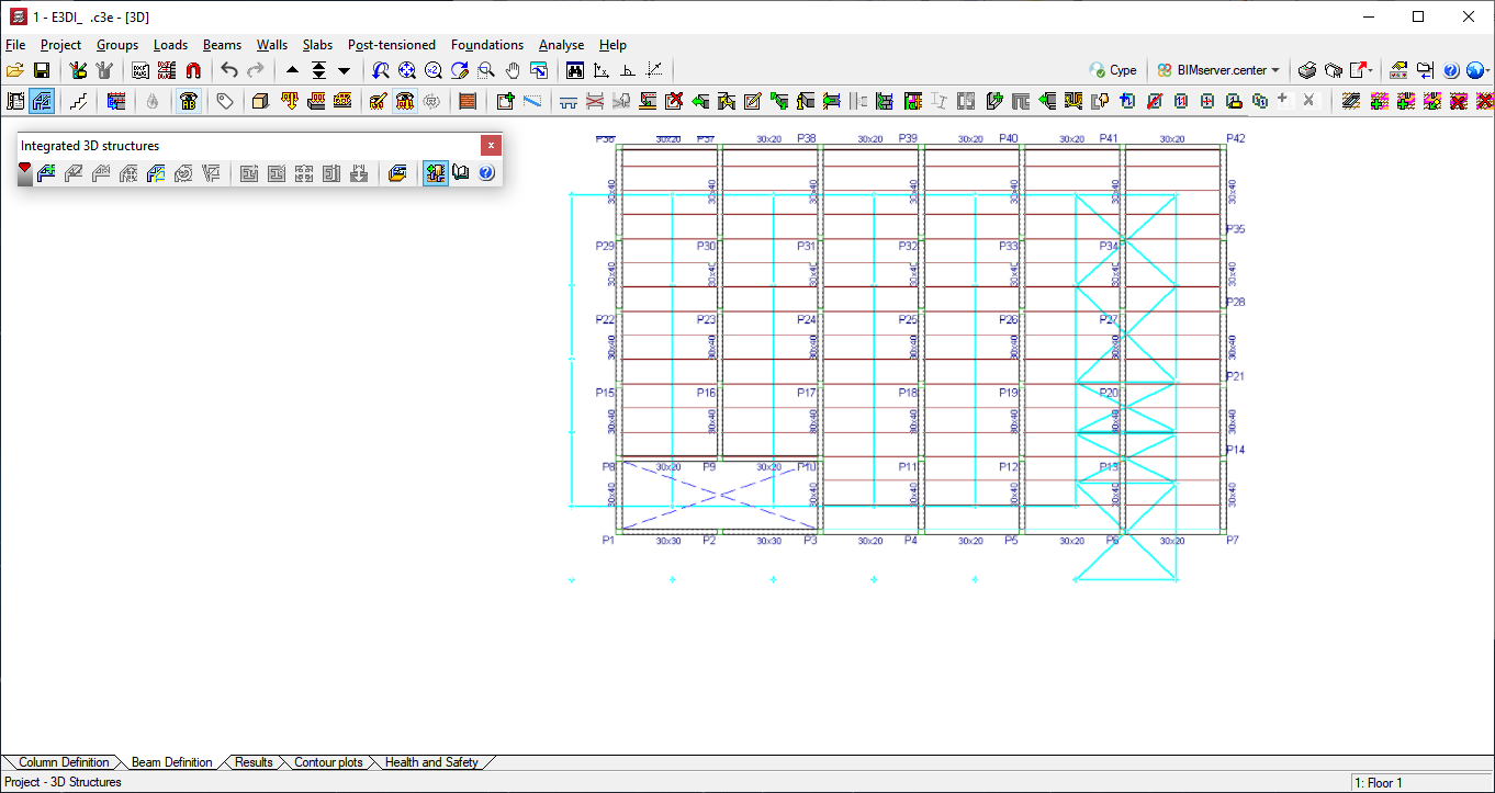
Creating an integrated 3D structure in CYPECAD
First of all, the connection points of the integrated 3D structure must be placed in the main CYPECAD job. Then, the 3D structure is defined in CYPECAD using the same working environment as in CYPE 3D. CYPECAD checks the position of the connections before defining the geometry of the 3D structure and generates error messages if these positions do not comply with the conditions indicated in the Connections of the integrated 3D structures with CYPECAD section.

Importing a job from CYPE 3D
CYPECAD allows users to import a job created in CYPE 3D as an integrated 3D structure. The nodes defined as external links in CYPE 3D will be the connections to the CYPECAD structure.
A CYPE 3D job can be imported into CYPECAD on a structure that has already been defined or on a new CYPECAD job that does not contain any structural elements:
- Importing into an existing CYPECAD job
With the CYPECAD job on screen, the user selects the CYPE 3D job to be imported by clicking on the button in the Integrated 3D Structures pop-up window (Project menu > Integrated 3D Structures). Then, the user positions the structure by taking an external link of the structure as a reference. The plan projection of the imported structure is shown on screen to make it easier to position. The remaining connections or external links of the integrated 3D structure are defined when the reference point is positioned and all the locations are checked when the 3D structure is edited or when the work is analysed.
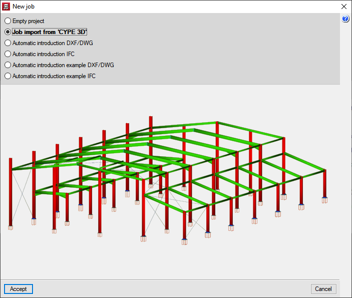
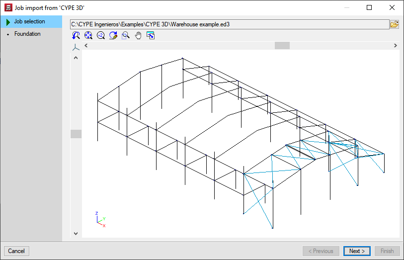
- Importing into a new CYPECAD job
When a new job is created in CYPECAD, the job introduction assistant appears which includes the Jop import from CYPE 3D option. If this option is activated, the program asks the user to choose the structure to be imported and also the type of foundation it will have:- Foundation with footing and pile caps
If this option is selected, CYPCAD generates column starts in each one of the supports of the structure. This way, users can define foundation with pad footing (both individual and combined) or with pile caps. - Mat foundation
If this option is selected, column starts will not be generated on the supports as it will not be necessary to introduce them when an integrated 3D structure is supported by a mat foundation. The supports of the CYPE 3D structure will be the connections to the mat foundation, which will be inserted later.
If the foundation of the structure is to have a footing or pile caps and the other is to have mat foundation, the Foundation with pad footings or pile caps option should be selected. Once it has been imported, users simply need to remove the unnecessary column starts in order to place the mat foundation under the supports.
- Foundation with footing and pile caps
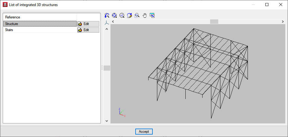
Editing integrated 3D structures
Once the integrated 3D structure has been entered using any of the methods described in the previous section (Ways of introducing integrated 3D structures), users have various options for modifying it: edit, delete, move, copy, rotate or align. All these options are located in the Project menu > Integrated 3D structures and have the following tools to make their use easier:
- Dialogue box icon
Help is available in the dialogue box where the option appears. - Step-by-step help
When users select the option, the program shows the steps to follow for its correct use at the bottom of the screen (under the Column definition and Beam definition tabs, etc.). This help is very useful, so it is important to pay attention to the instructions provided, especially when you are not familiar with the option you are using. - Provisional view of the structure’s new position
With the move, copy, rotate or align options, the program displays (as the mouse is moved) the provisional position of the integrated 3D structure after selecting the reference point and before selecting its next position.
These editing options are detailed below:
Edit integrated 3D structures
With this option, users can modify an integrated 3D structure that has already been introduced in CYPECAD. To do this, the user simply selects a connection of the structure or the projection of the structure with the left mouse button.
Delete integrated structures
This option allows users to delete one or more integrated 3D structures. To delete a 3D structure, the user simply selects a connection of the structure to be deleted or the projection of the structure with the left mouse button. Several structures can also be deleted via a selection window. When deleting an integrated 3D structure, all of its connections are also deleted automatically.
Move integrated structures
This option allows users to move an integrated 3D structure. Using the left mouse button, the user selects one of the connections of the structure they wish to move and place it in the new position.
Copy integrated structures
This option allows users to create a new integrated 3D structure in the current group from a previously entered one in any group.
Rotate integrated structures
This option allows users to rotate an integrated 3D structure. Rotating an integrated 3D structure can be carried out in two ways:
- Indicating the numerical value of the rotation angle
- Selecting the integrated 3D stucture to be rotated
- Selecting the rotation point
- Indicating the rotation angle
- Graphically, by means of reference points
- Selecting the integrated 3D stucture to be rotated
- Selecting the rotation point
- Selecting the reference point
- Selecting any point on the line connecting the rotation point to the future position of the selected reference point
Rotating horizontal loads
If there are horizontal loads, such as wind loads, the program analyses and manages their rotation together along with that of the integrated 3D structure. The program will ask the user to confirm different actions, depending on whether or not the structure has loads included in loadcases that are also used in other integrated 3D structures or in the CYPECAD project:
- The horizontal loads of the integrated 3D structure to be rotated act on loads not used by other integrated 3D structures or by the CYPECAD project
In this case, the program asks the user to select the combination of these loadcases between them and with other loadcases of horizontal loads of the same type (wind, for example) that may exist in the CYPECAD structure or in other integrated 3D structures. By default, the program analyses them as independent loadcases, meaning that they do not act simultaneously with each other. - The horizontal loads of the 3D integrated structure to be rotated act on loadcases also used by other integrated 3D structures or by the CYPECAD project
The program asks the user to choose between the following two actions:
- Keep the horizontal loads of the integrated 3D structure to be rotated in the loadcases where they are located to then check their validity.
- Apply the horizontal loads of the integrated 3D structure to be rotated in new additional loadcases automatically created by the program.
In either case, the program then displays the dialogue box where the loadcases can be combined, just as it does when the loads of the integrated 3D structure to be rotated belong to loadcases that are not used by other integrated 3D structures or by the CYPECAD project.
Align integrated structures
Esta opción permite aliThis option allows an integrated 3D structure to be aligned. The alignment of the structure consists of a displacement and a rotation. The alignment of an integrated 3D structure is carried out by selecting two reference points and indicating their new position. The reference points do not necessarily have to be points on the structure. The alignment process is as follows:
- Selecting the integrated 3D structure to be aligned
- Selecting the first reference point
- Selecting the new position of the first reference point
- Selecting the second reference point
- Selecting any point on the straight line that will join the new positions of the reference points
Rotation of horizontal loads
Since the alignment of an integrated 3D structure is made up of a displacement and a possible rotation, when there are horizontal loads, such as wind loads, the program analyses and manages its rotation together with that of the integrated 3D structure if the alignment process causes the structure to rotate. The program will ask the user to confirm different actions, depending on whether or not the structure has loads included in loadcases that are also used in other integrated 3D structures or in the CYPECAD project:
- The horizontal loads of the integrated 3D structure to be rotated act on loadcases not used by other integrated 3D structures or by the CYPECAD project
In this case, the program asks the user to select the combination of these loadcases between them and with other loadcases of horizontal loads of the same type (wind, for example) that may exist in the CYPECAD structure or in other integrated 3D structures. By default, the program analyses them as independent loadcases, meaning that they do not act simultaneously with each other. - The horizontal loads of the 3D integrated structure to be rotated act on loadcases also used by other integrated 3D structures or by the CYPECAD project
The program asks the user to choose between the following two actions:
- Keep the horizontal loads of the integrated 3D structure to be rotated in the loadcases where they are located to then check their validity.
- Apply the horizontal loads of the integrated 3D structure to be rotated in new additional loadcases automatically created by the program.
In either case, the program then displays the dialogue box where the loadcases can be combined, just as it does when the loads of the integrated 3D structure to be rotated belong to loadcases that are not used by other integrated 3D structures or by the CYPECAD project.
Benefits for CYPECAD with Integrated 3D Structures
Integrated 3D structures give CYPECAD the power and possibilities of CYPE 3D. The virtues of these two important analysis tools are therefore united in a single program.
For Integrated 3D Structures, CYPECAD has its own modules available, along with those it shares with CYPE 3D as well as the latter's exclusive modules.
Other features
In order to access further features offered by the program, there are several modules that can be found on the "CYPECAD modules" and "CYPE 3D modules" webpages.