
Options in the "Connections" tab
The upper tab "Connections" (accessible within the lower tab "Structure") contains the tools to perform the design and analysis of the structure's connections. The upper ribbon includes:

- in the first group, the options for entering a new connection at a node, at the end of a part or between a group of parts, deleting it or editing it;
- in the second group, the options for assigning the characteristics of one connection to another, grouping or ungrouping compatible connections, locking or unlocking connections so that they are not modified during the calculation, or searching for connections by their reference;
- and in the third group, the options for the automatic generation of connections and for consulting or modifying the values of the rotational stiffnesses assigned to the ends of the parts.
Entering connections
The following options, available in the upper toolbar of the "Connections" tab (in the "Structure" tab), are used to enter and remove connections in the structure.

If no connections have been entered, only the "New" and "Generate" options will be active.
New
The "New" option can be used to enter a connection manually in the model:
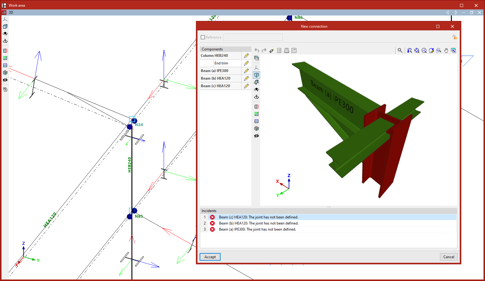
- To create a connection that considers all the bars in a node, select the node with the left mouse button. The connection editing window will open, where you can adjust the components of the connection. Then click on "Accept".
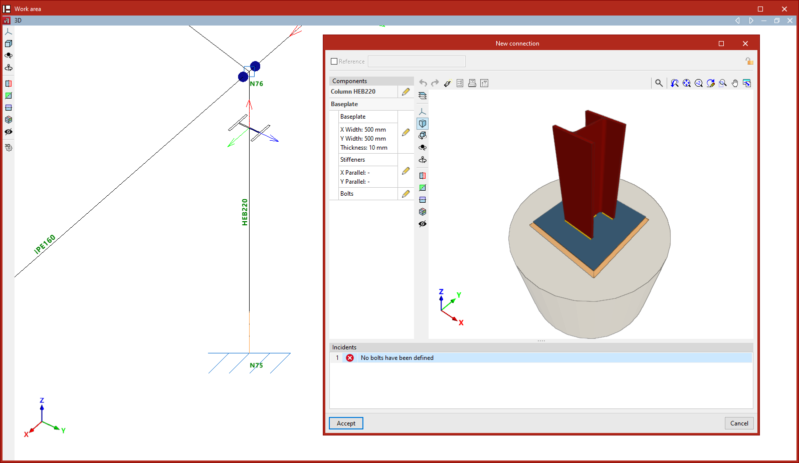
- To create a connection at the end of an element, e.g. a baseplate, select the end of the element with the left mouse button and click the right mouse button. You can also select the end node with the left mouse button if it is the only part that uses it. Similarly, the connection editing window is then accepted.
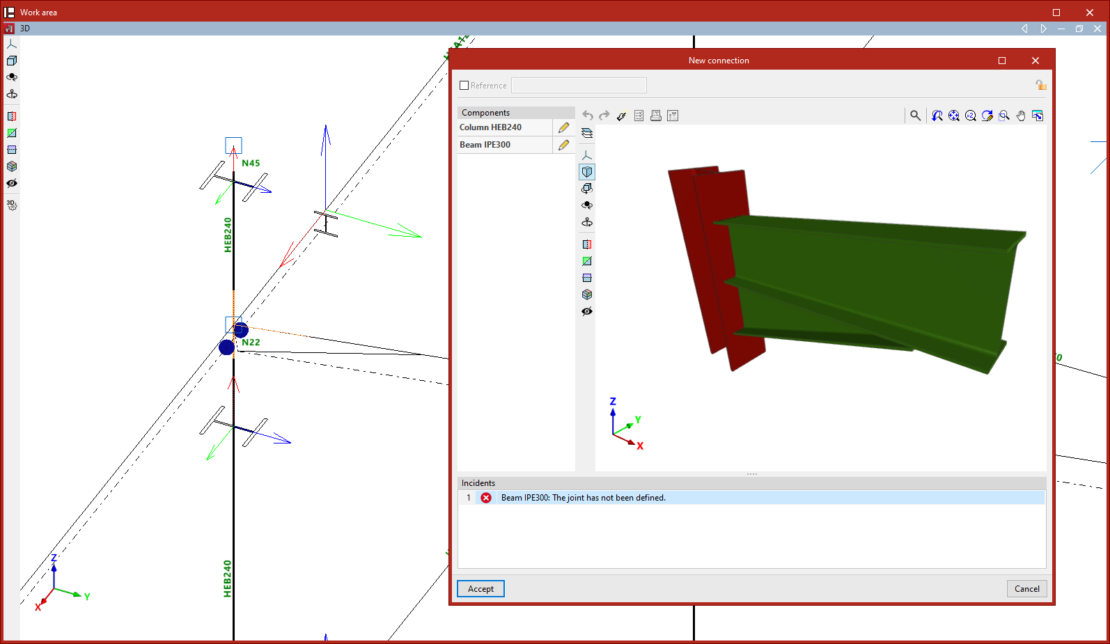
- To create a connection between a group of elements, select the elements with the left mouse button by clicking on an area close to the node where you want to create the connection and then press the right mouse button. The connection editing window is then accepted. More than one connection can be defined in the same node by selecting different groups of elements.
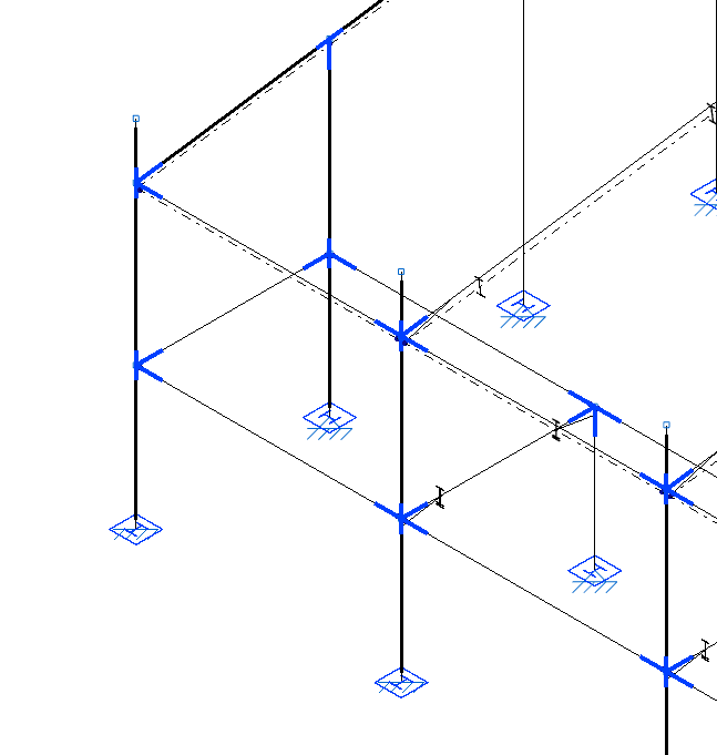
The created connections are shown in blue in the model viewer.
Delete
Once the connections have been entered in the project, the rest of the options are available in the "Connections" tab.
The "Delete" option can be used to delete the created connections by selecting them one by one with the left button or by using the crossing method to select several at the same time. Afterwards, right click to confirm the removal.
Editing connections
Connections in the model are edited with the following option, available in the upper toolbar of the "Connections" tab (in the "Structure" tab).

Edit
After clicking on the "Edit" option, a joint or a group of joints is selected by left-clicking on them.
The program opens the corresponding editing window, with the sections listed below.
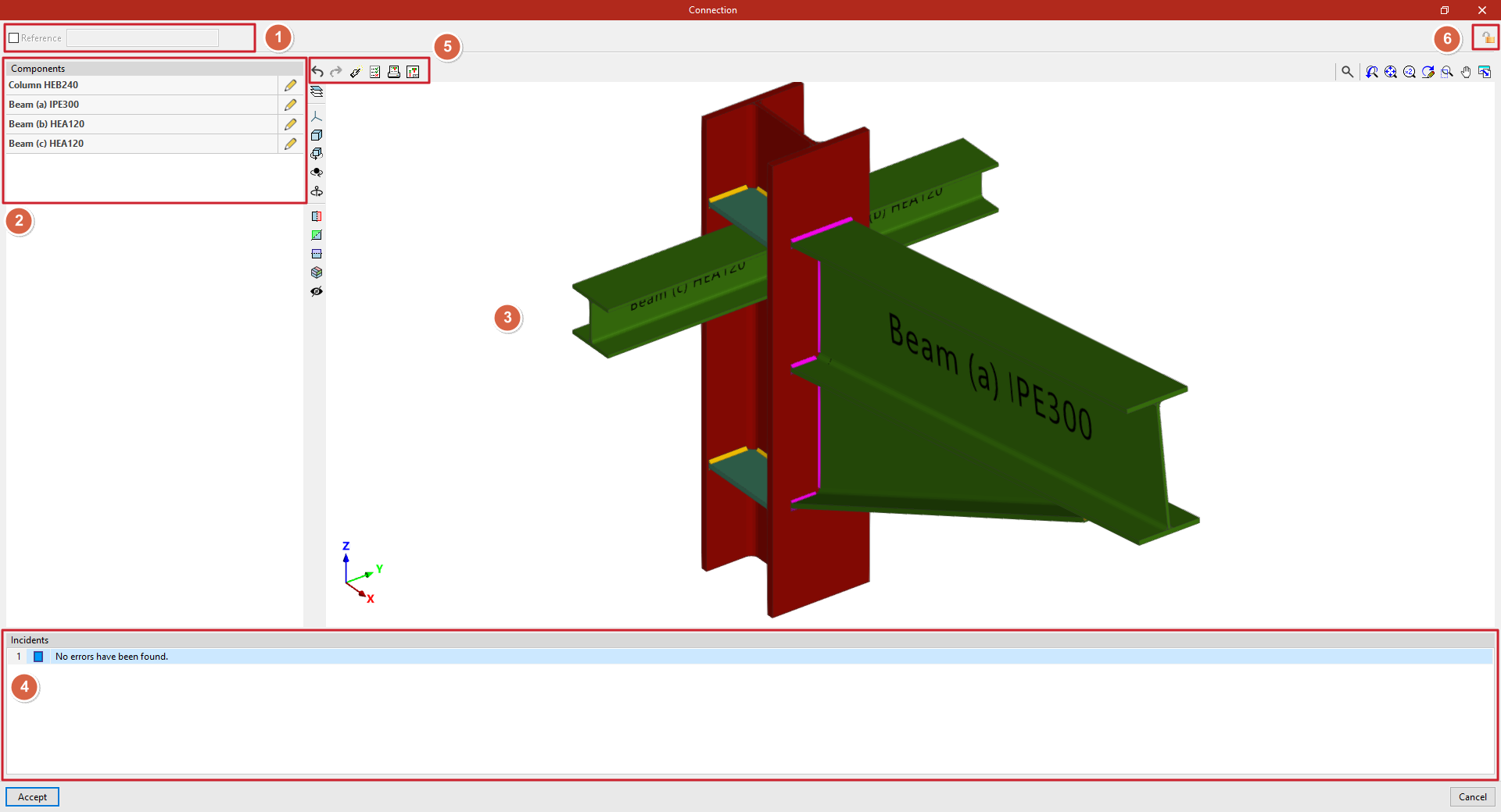
Reference (1)
First, the top box can be activated to assign a "Reference" to the selected connection.
Components (2)
On the left-hand side, the list of "Components" involved in the connection is presented, together with the "Edit" option to make modifications to each of them.
3D viewer (3)
In the central area, the connection is displayed in 3D. Each component shows its reference and section for easy identification.
To the left of the 3D view, there are visibility controls for the "Elements" of the connection. You can also modify the "Projection", the "Projection type" and use tools to rotate or cut the view.
Issues (4)
In the lower part, the list of "Issues" detected in the connection is displayed.
Possible warnings include: "The joint has not been defined", component definition errors, "No errors have been found" or "The project is not analysed".
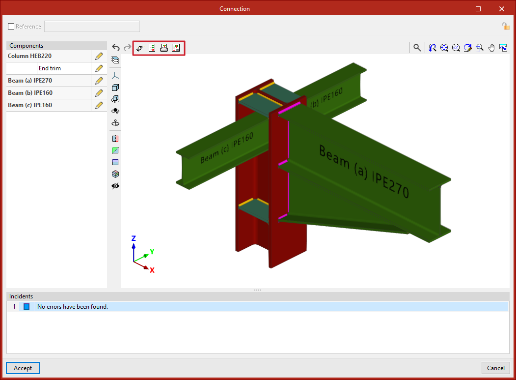
Tools at the top(5)
At the top of the viewer, there are options for designing, checking and obtaining detailed information about the connection.
To the left of this area, there are options to "Undo" and "Redo" any changes applied to the components.
Lock (6)
If you wish to prevent the program from automatically modifying a joint when using the "Design" option, you can lock the connection by clicking on the corresponding button at the top right. To unlock it, simply click on the padlock icon again.
Finally, after clicking "Accept", you return to the general program interface. The connections will be displayed in different colours depending on whether or not all the checks have been verified.
Designing, checking and obtaining the report and detailing of each connection
The tools for designing, checking, and obtaining the complete report of the connection and the detailing of each connection individually are available at the top of the editing window.
This window is accessible by clicking the "Edit" button on each group of connections, within the top toolbar of the "Connections" tab (under the "Structure" section).
These tools are explained below.
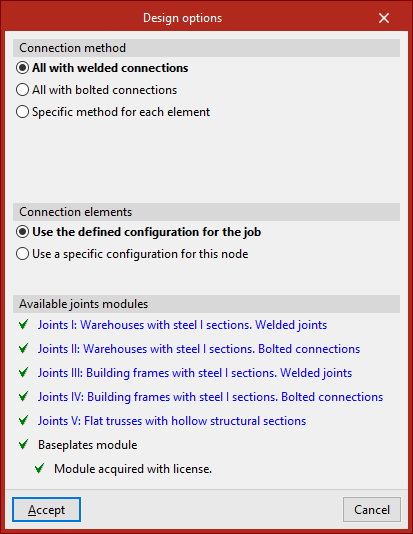
Design
Using the "Design" option, the program automatically generates the necessary components in each part to comply with the relevant standards.
To define the "Connection method", you can choose between "All with welded connections", "All with bolted connections", or set a "Specific method for each element".
Regarding the "Connection elements", you can opt to "Use the defined configuration for the job" or "Use a specific configuration for this node".
In the latter case, by clicking "Options", you can define parameters related to bolts, stiffeners and baseplates.
Further down, the program displays the "Available joints modules" depending on the license. Each module can be reviewed by clicking the corresponding links.
After clicking "Accept", the program asks whether you wish to view the full report of the code checks performed on all elements of the connection.
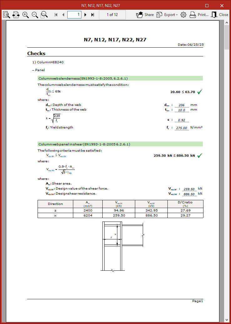
Code checks
This report can also be generated via the "Code check" option located at the top of the viewer, which allows you to check the elements in their current state.
In the pop-up window that appears after pressing this button, you can select each "Element" from the left column.
At the top right, the "Verifications" carried out on that element are listed, including its "Status" (whether it is "Verified" or not) and the relevant "Zone".
By selecting each line, you can access the full details of the verification at the bottom, including standard references and calculations.
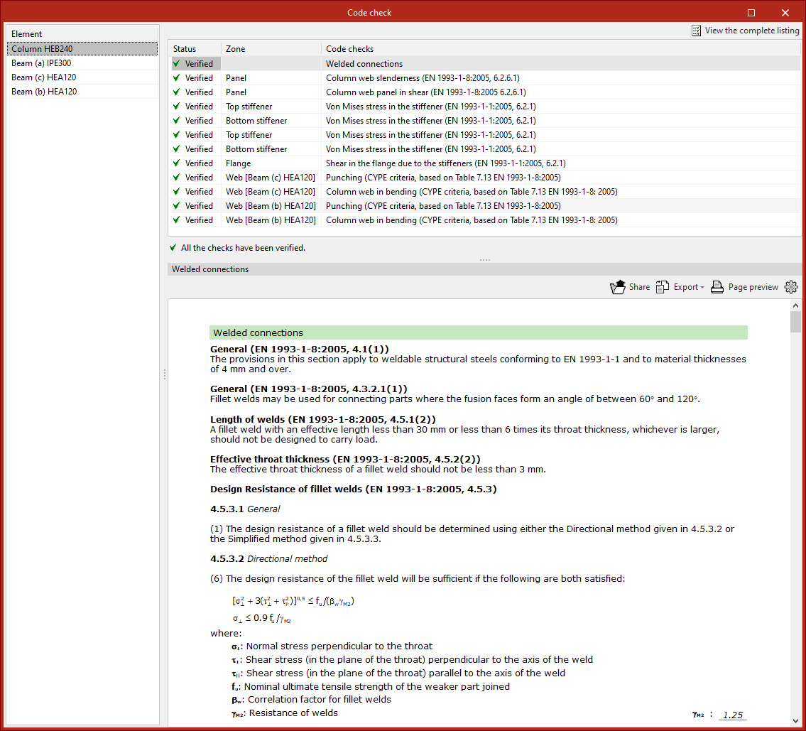
It is also possible to "View the complete listing" of the connection from the top right.
This report can be "Shared", "Exported" in various formats or "Printed".
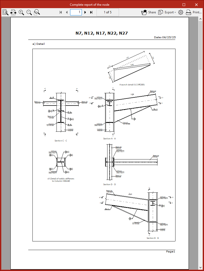
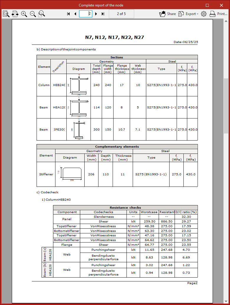
Full report of the node
Another available option is to obtain the "Complete report of the node", which includes "Detail drawings", a "Description of the connection components", and summary "Verification" tables.
This report can also be "Shared", "Exported" or "Printed".
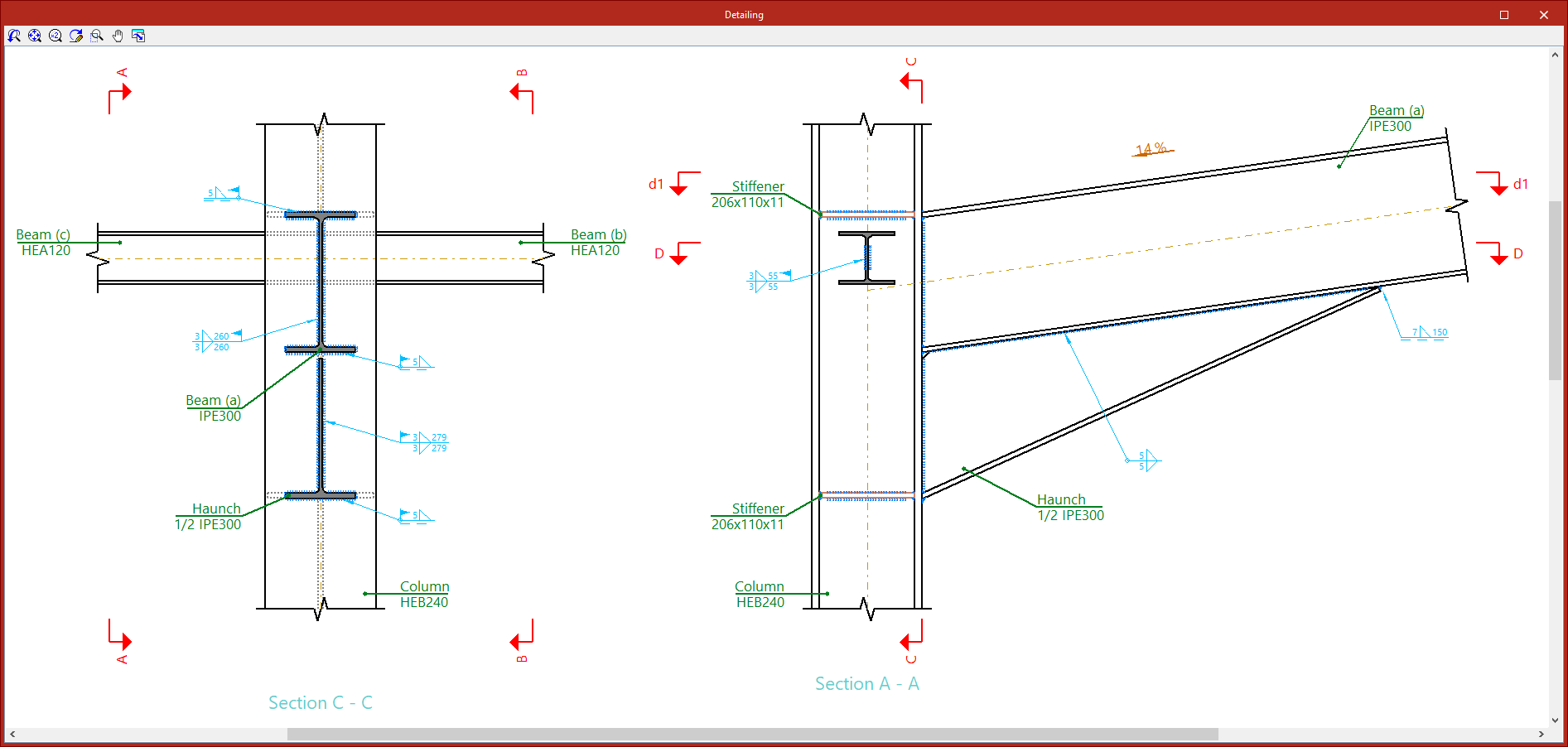
Detailing
With the "Detailing" options, a detailed view of the connection shell is generated. Although the general shell is printed along with the drawings, it is also possible to "Print the current view" directly from here.
Generating connections
The automatic generation of the structure’s connections is carried out using the "Generate" option, available in the top toolbar of the "Connections" tab (under the "Structure" section).

If no connections have been entered, the options "New" and "Generate" are the only ones shown as active.
Generate
The "Generate" option allows you to generate the structure’s connections automatically. To do this, the program analyses all nodes in the project and assigns detected connections to those parts that do not already have a defined connection.
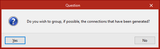
After clicking on the option, you must indicate whether you wish to group the generated connections where possible.
Later, in the "Information" window, the number of generated connections is displayed.
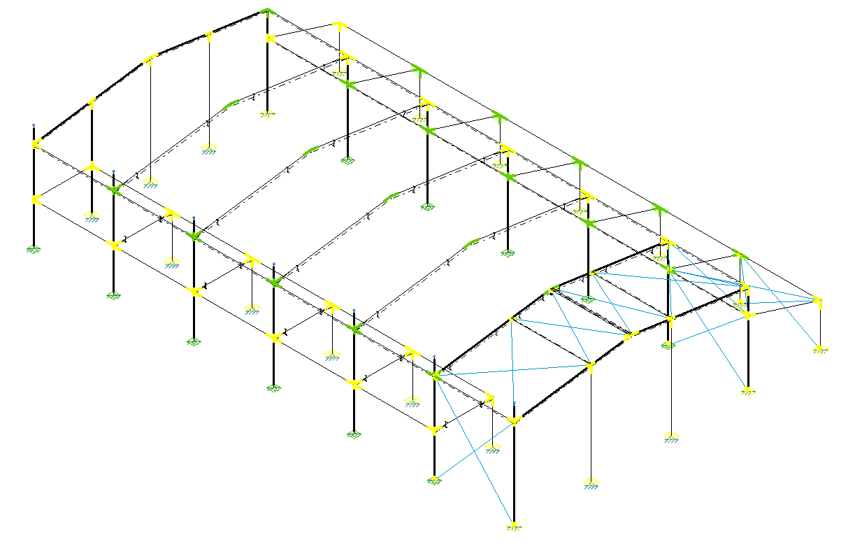
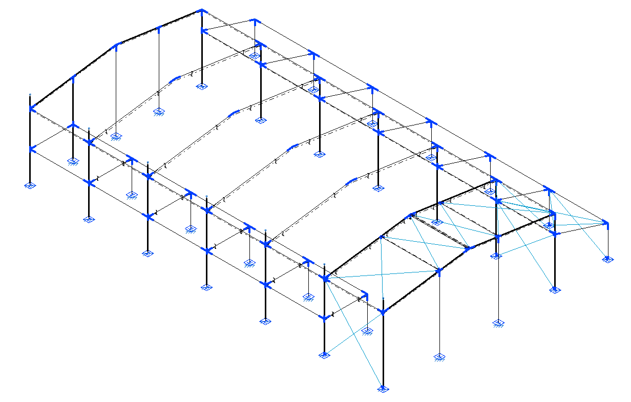
After clicking "Accept", all nodes where a connection has been detected and generated will appear in blue in the model viewer.
| Note: |
|---|
| The generation of connections depends on the geometry of the connections, the number of bars and their cross-section, the orientation of the section, the parts created, and the presence or absence of hinges at the ends of the bars. If the program does not generate a connection at a specific point, these aspects can be reviewed so that the connection defined in the model matches one of the connection types the program is able to identify. |