
Options in the "Load" tab
The upper tab "Load" (accessible from the lower tab "Structure") contains the options for displaying, entering and editing loads on nodes, bars, shells and panels, as well as surface loads. It includes the following:
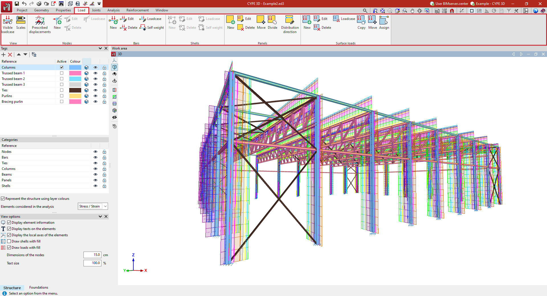
- in the "Display" group, the options for managing the display of loads in the work area;
- in the "Nodes" group, the options for entering and editing loads on nodes, as well as the option for defining prescribed displacements;
- in the "Bars" group, the options for entering and editing loads on bars, including the activation or deactivation of the generation of self-weight loads;
- in the "Shells" group, the options for entering and editing loads on sheets;
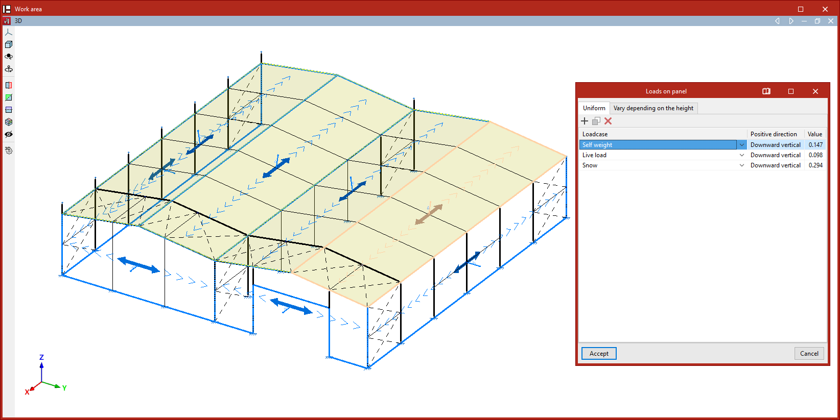
- in the "Panels" group, the options for entering and editing load panels, which allow loads to be applied to the geometry of the wall and, in addition, to control the distribution of the loads arranged in the wall on the elements of the structure;
- and in the "Surface loads" group, the options for entering and editing surface loads.
Load visualisation options
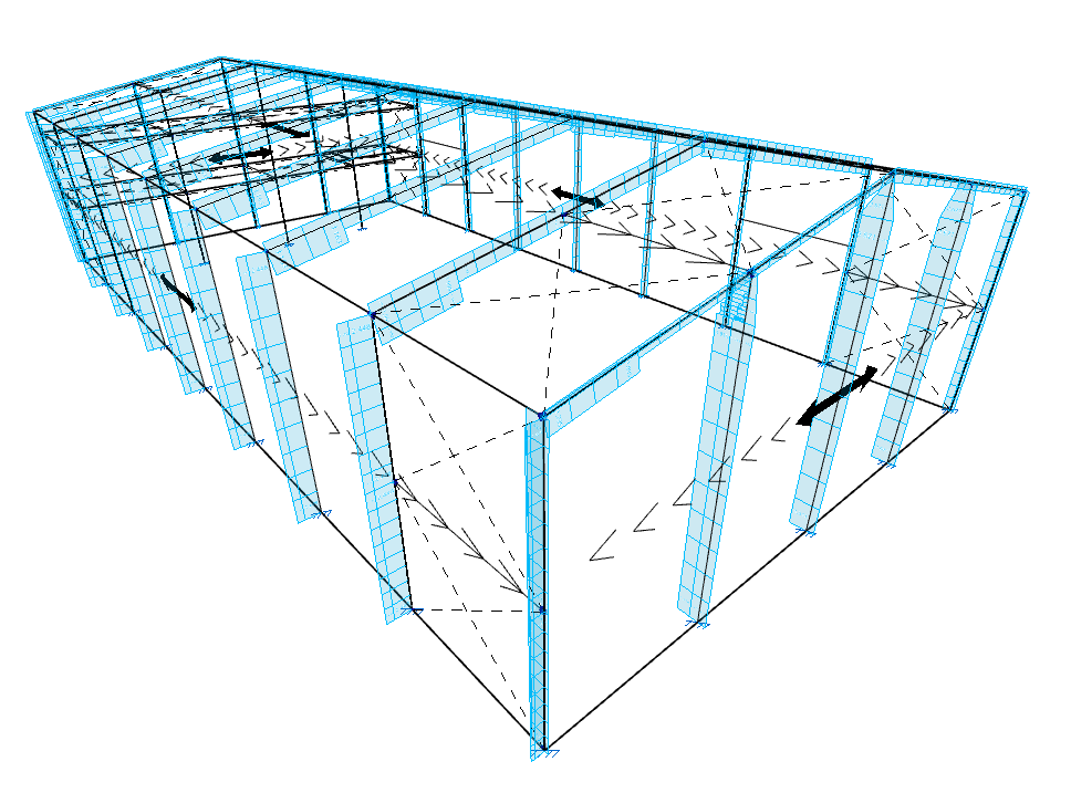
The options for editing the visualisation of load cases and adjusting their scale are available in the "View" group on the top toolbar, within the "Load" tab (under the "Structure" section).

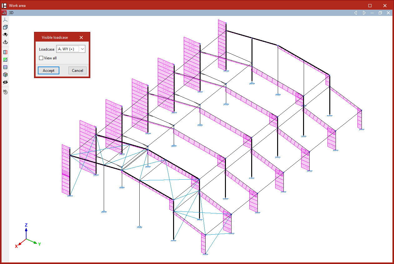
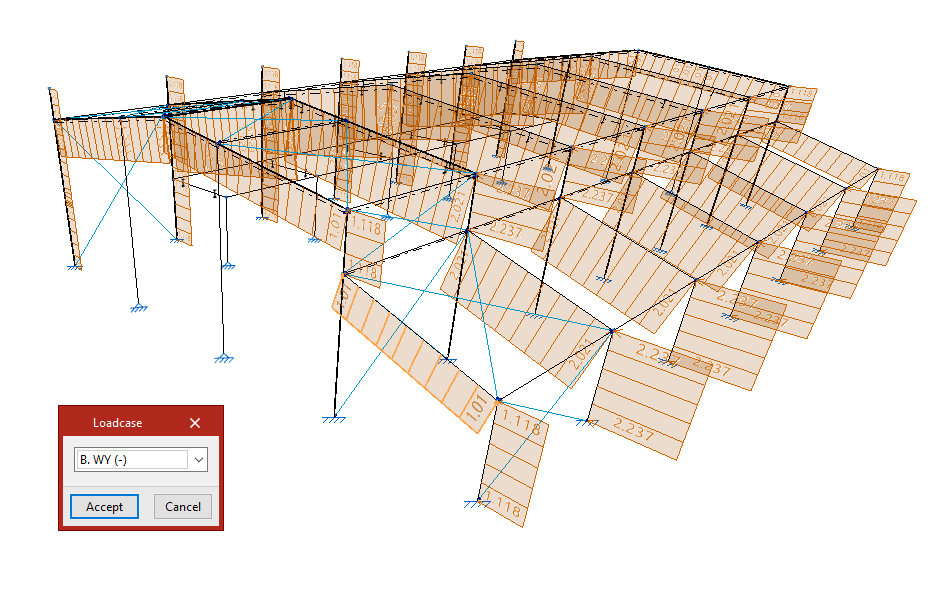
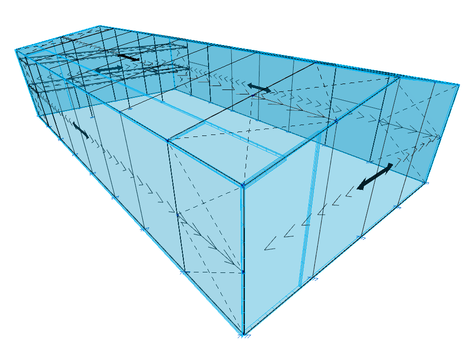
Visible load case
The "Visible load case" option allows you to select which load case to display. In the pop-up window, choose the active "Load case" from the dropdown menu, then click "Accept".
The loads assigned to the selected case will then be shown in the model viewer. For each load, the program displays its direction of application and value in the selected units.
For surface loads and loads on panels, the program will display the resulting line loads on the bars after distribution.
From this point on, any new loads inserted will, by default, be assigned to the selected load case.
If you access the same option again, you will see that it is also possible to activate the "View all" checkbox. When enabled, the model will display the loads assigned to all load cases, each shown in a different colour.
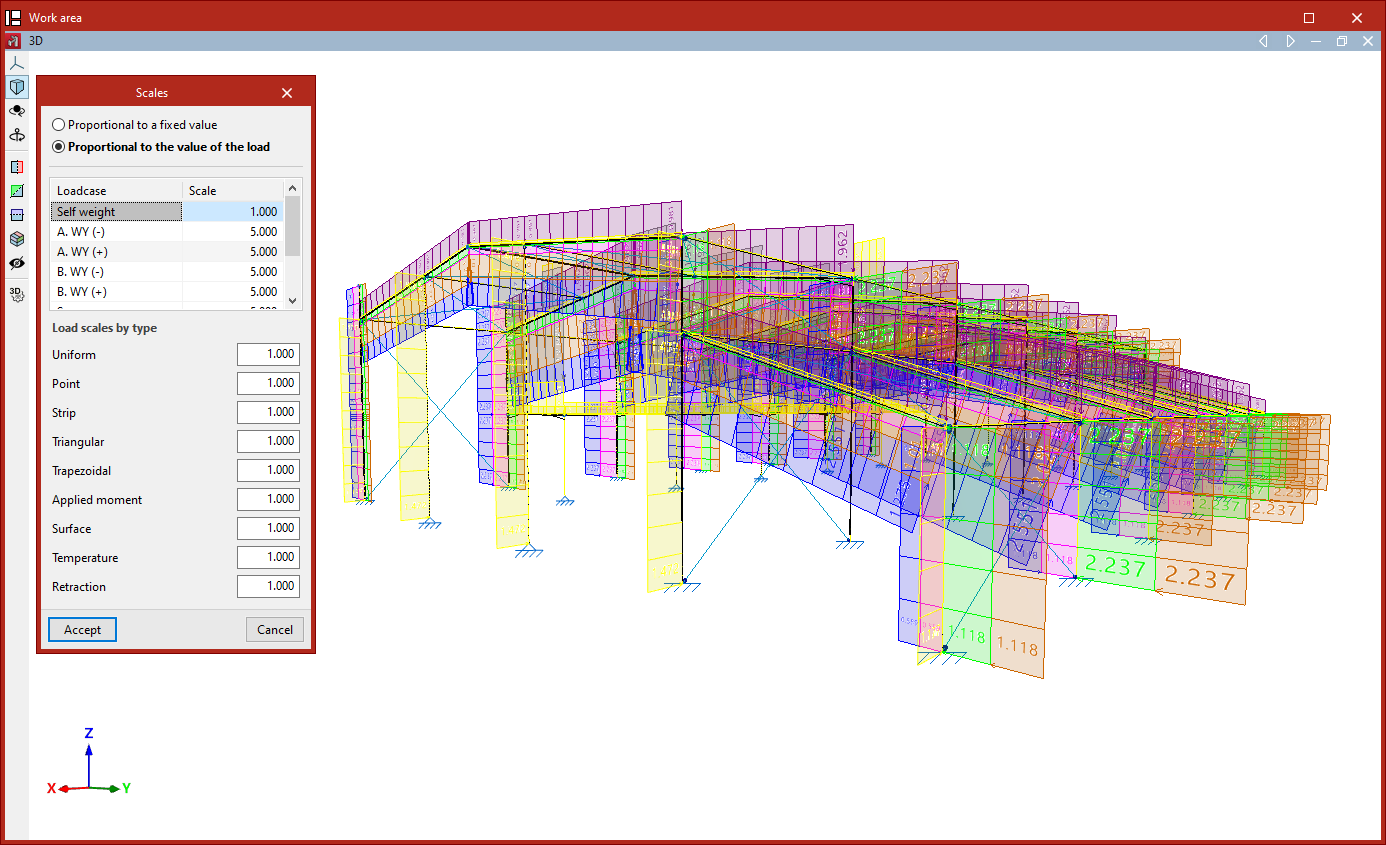
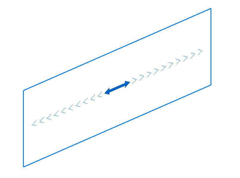
Scale
The "Scale" option allows you to adjust the drawing scale for load representations.
First, you can choose between "Proportional to a fixed value", in which case you specify the "Maximum representation size", or "Proportional to the load value".
If you select the latter, and you wish to edit the scale for each defined "Load case", you can input the scale factor for each case in the central table.
You can also specify "Load scale by type" values, which apply to the following load types:
"Uniform", "Point", "Strip", "Triangular", "Trapezoidal", "Applied moment", "Surface", Temperature", and "Retraction".
These values act as multipliers to the previously defined scale values.Finally, click "Accept" to apply the changes and adjust the size of the load representations in the viewer.
Applying prescribed displacements and rotations
Prescribed displacements or rotations can be applied using the following option, available in the "Nodes" section of the top toolbar, within the "Load" tab (under the "Structure" tab).

Prescribed movements
This option allows you to apply a translation or rotation to nodes or edges of shells with external fixity.
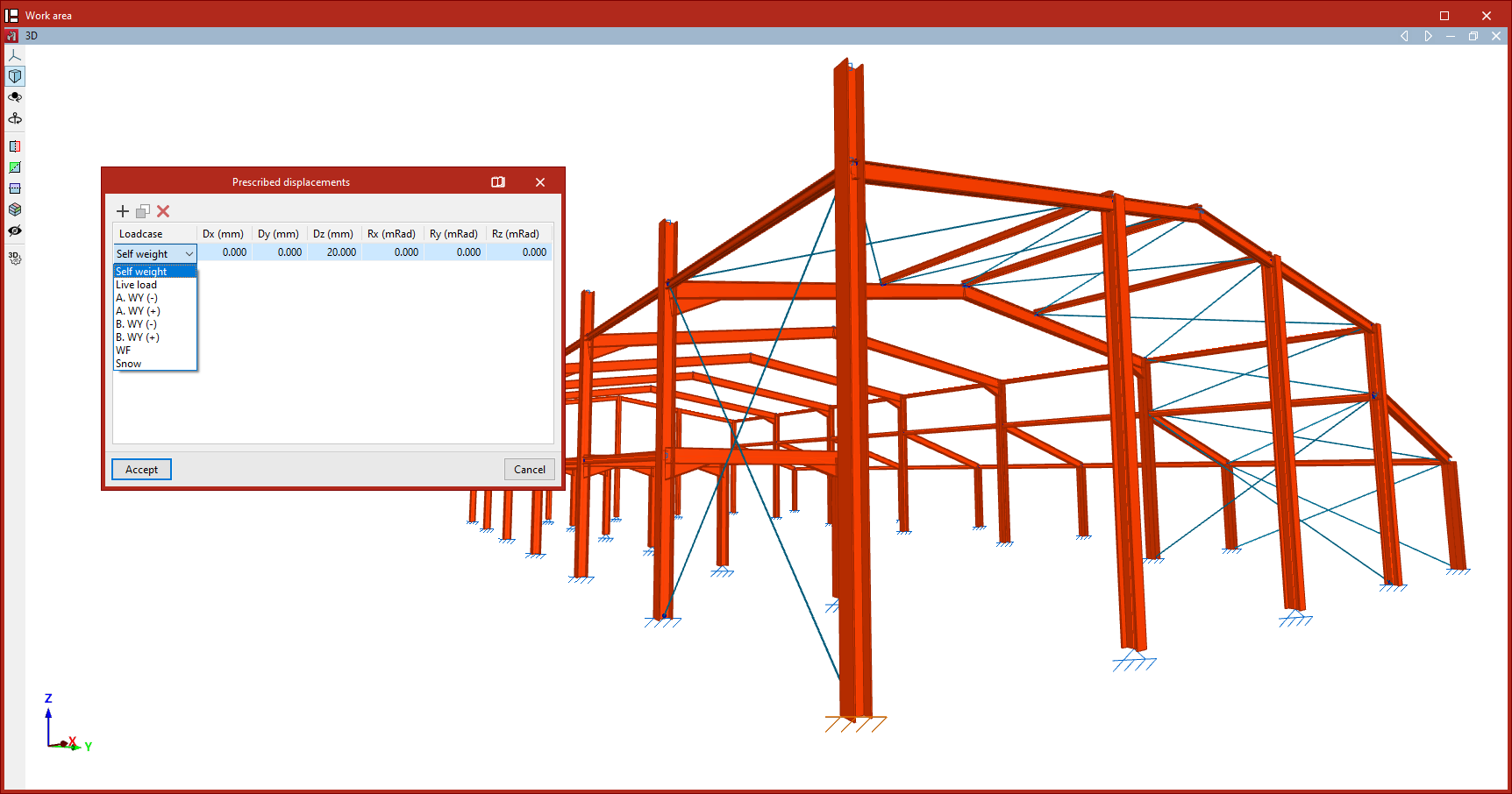
First, select the vertices or edges one by one using the left mouse button, or by dragging to select an area. Then, click the right mouse button.
This opens the "Prescribed displacements" window. Here you can "Add", "Copy" and "Delete" displacements and rotations for each of the project loadcases.
Clicking "Add" creates a row in the table.
In the drop-down menu in the first column, select "Loadcases" from the list of available simple loadcases.
The table will then have a maximum of six additional columns, corresponding to the translations (Dx, Dy, Dz) and rotations (Rx, Ry, Rz) in the three spatial directions. The number of columns depends on the constraints or restricted movements at the selected nodes or edges.
Six additional columns are displayed at a fixed connection; three columns are displayed at a hinged connection; and a single additional column is displayed at a sliding support in a plane.
In each of these columns, you can enter the desired displacement or rotation value for the specified scenario. The units in which these values should be entered are indicated in the table header.
The assignment of prescribed displacements at nodes or edges results in forces appearing in the structure during the analysis, which can be viewed subsequently.
To include displacements or rotations in other loadcases, further rows are added to the table.
The forces resulting from the displacements or rotations inserted will be affected by the combination factors applied to the selected loadcase.
Finally, click "Accept". The nodes or edges with specified displacements will change colour so that they can be identified in the model.
| Note: |
|---|
| A common example of the application of prescribed displacements would be the settlement of a foundation (Dz), which would result in corresponding forces in the structure connected to that support. |
Entering and editing loads on nodes
The following options are used to enter and edit loads on the nodes of the structure, which are available in the "Nodes" group of the upper toolbar, in the "Load" tab (in the "Structure" tab):

New
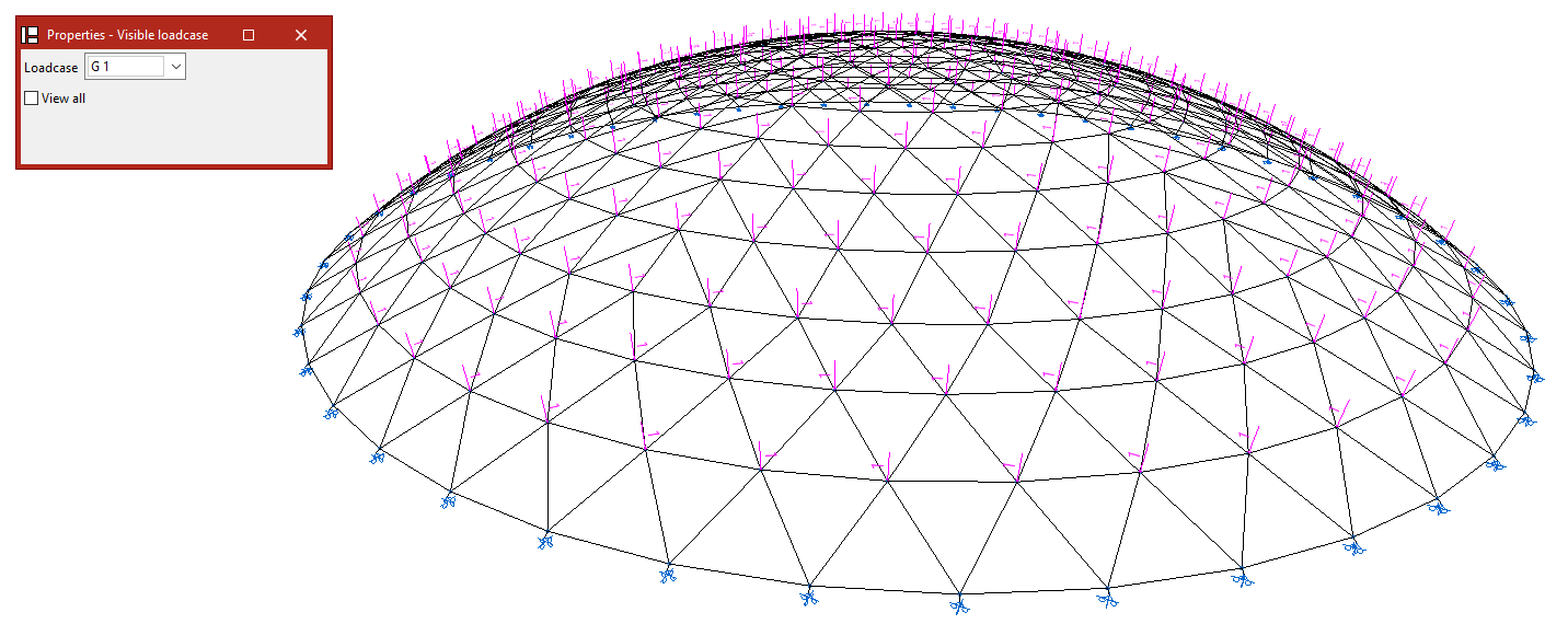
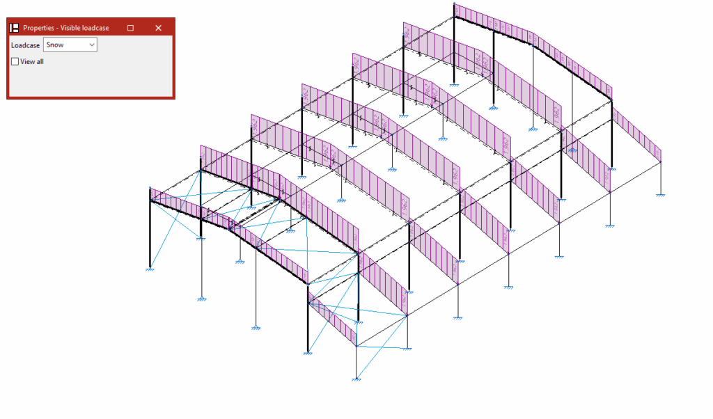
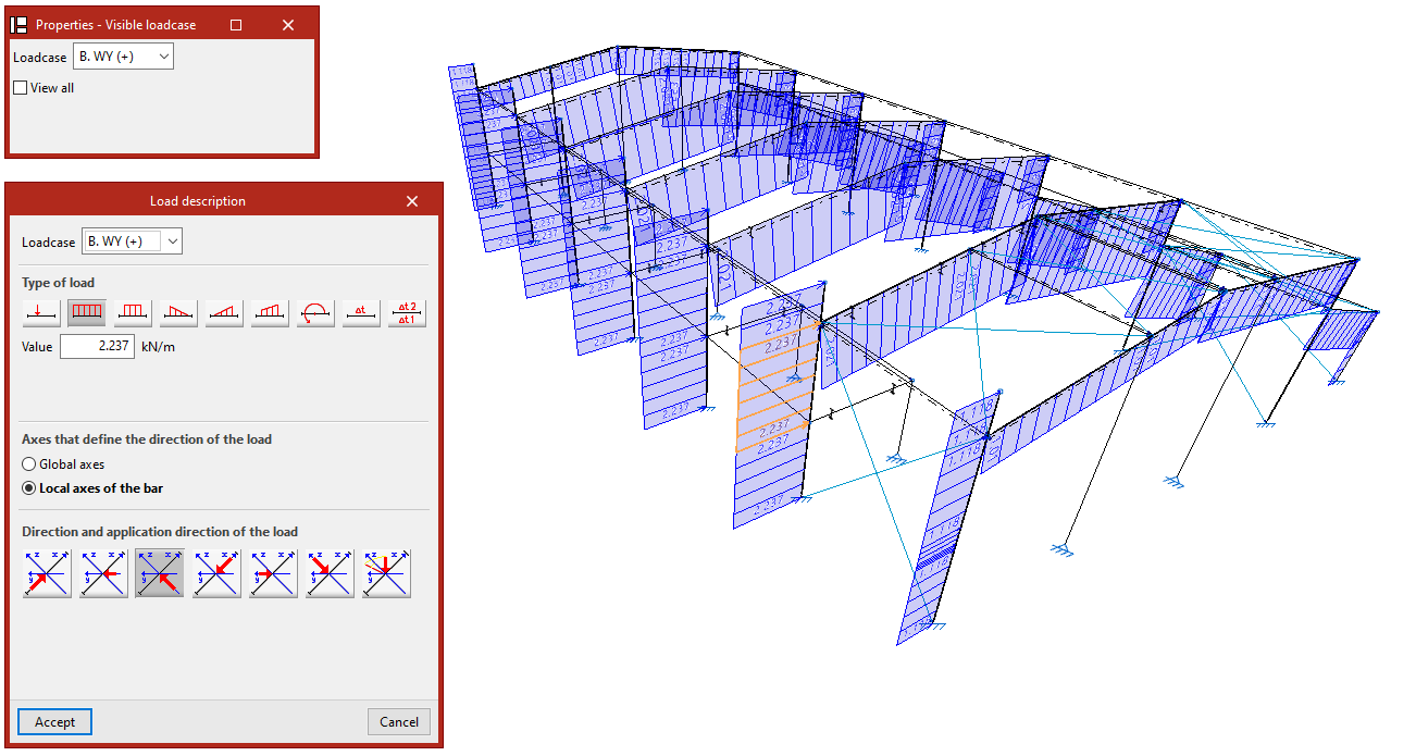
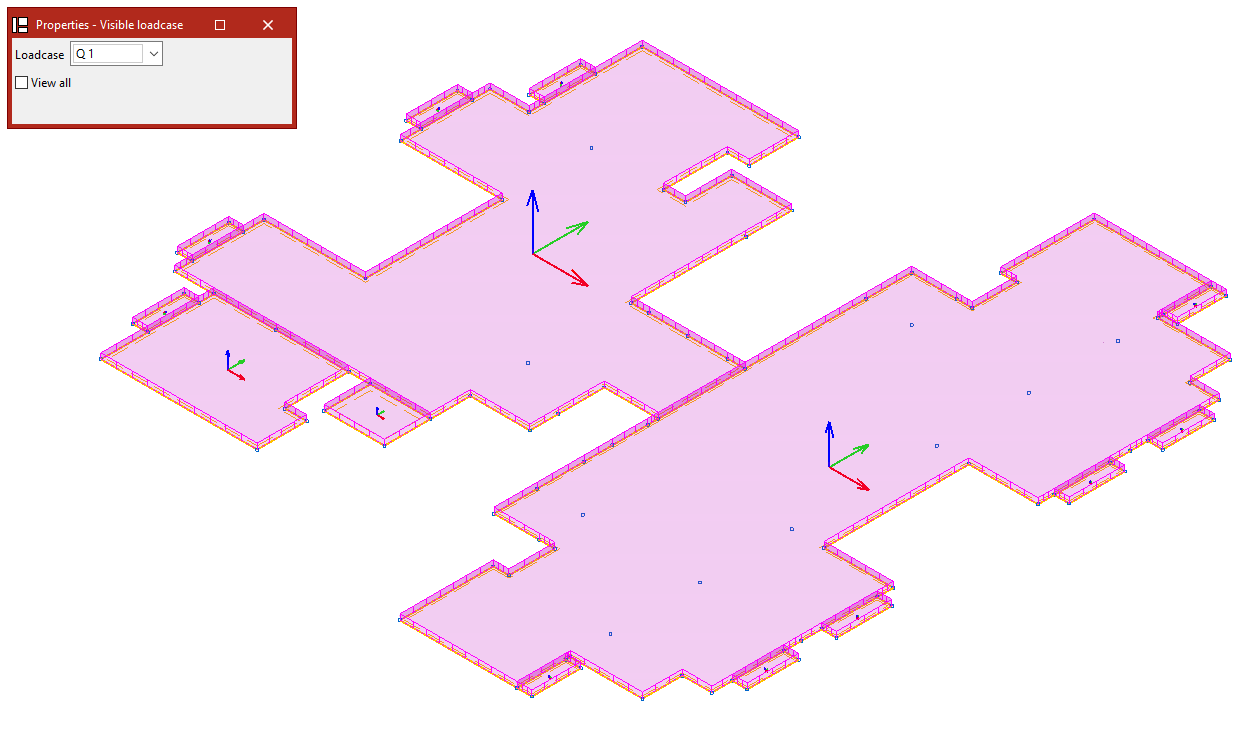
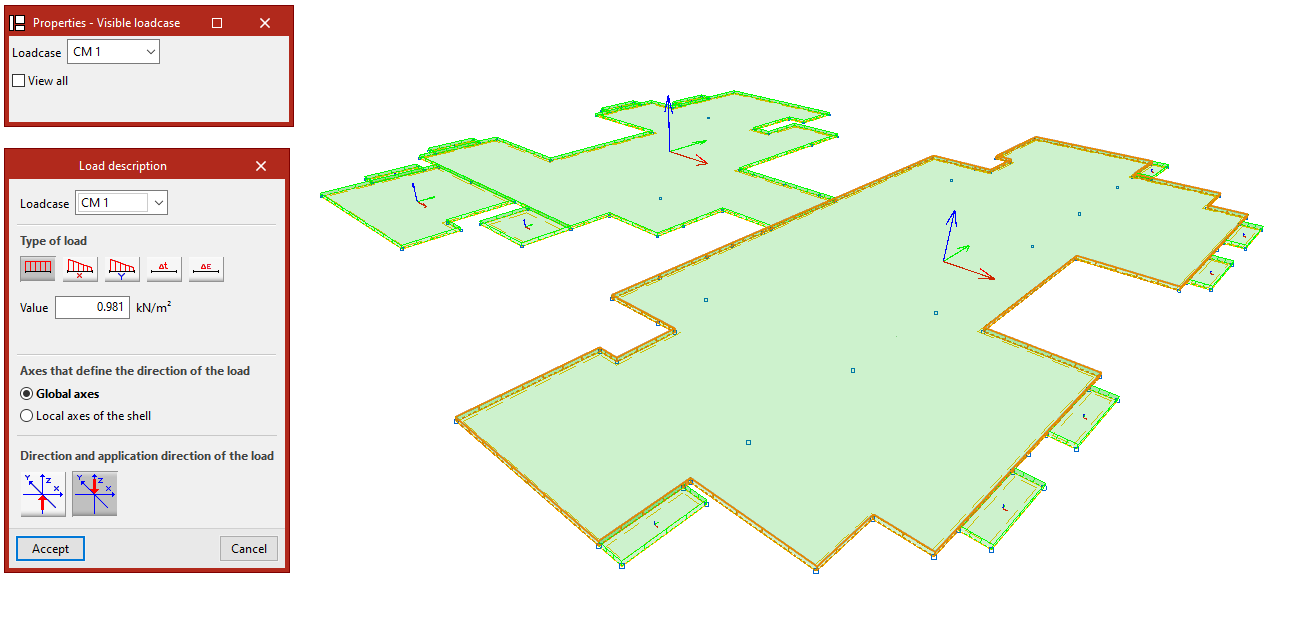
When selecting the "New" option, the "Properties - Visible loadcase" window appears, where users can choose the "Loadcase" to be displayed. Alternatively, users can "View all" loadcases by checking the corresponding box.
Then, click on the nodes one by one or use the crossing method to select several nodes simultaneously.
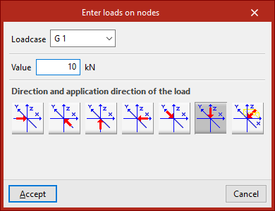
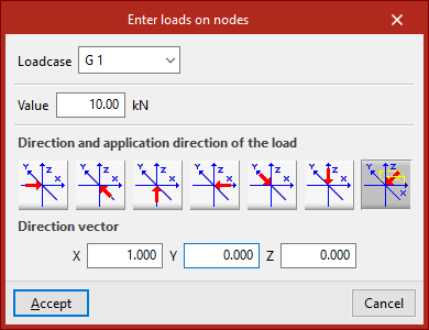
Right-click on a node to open the "Enter loads on nodes" window. Here, the "Loadcase" to which the new loads are to be assigned is selected. Then its "Value" is typed in.
The "Direction and application direction of the load" is indicated at the bottom. Here you can take the directions of the global axes in both directions or freely define one direction. By default, the program selects the most common case, which is a load in "Direction, according to the Z axis, in the negative direction". The last option, "Define direction", applies the load in the direction defined by the "Direction vector" components entered by the user.
After clicking on "Accept", the program will apply the load on the selected nodes.
The following options in the "Nodes" group are activated when loads on nodes have been previously entered:
Edit
The "Edit" option is used to modify the loads on nodes that have already been entered.
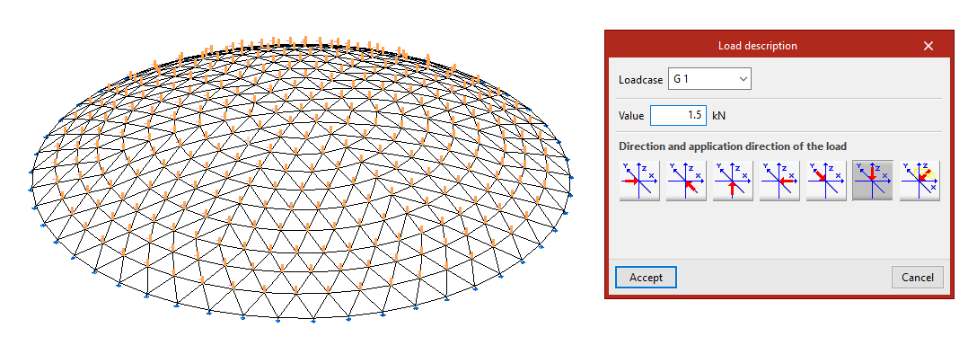
In the "Properties - Visible loadcase" window that appears, select the "Loadcase" to which the loads to be edited are assigned so that they are visible in the model. The loads are then selected by clicking on them one by one or via a selection window.
By right-clicking, the "Load description" window appears, where the load data can be modified. The same options are offered here that appear when entering the loads. Finally, click on "Accept".
Delete
The "Delete" option is used to remove the selected loads on nodes from the model. In the same way, left-click on the loads to select them one by one or use the crossing method to select them all at once and then right-click to delete them.
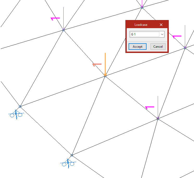
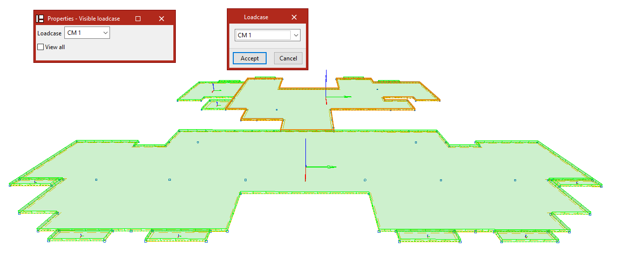
Loadcase
If only the loadcase of the loads on nodes needs to be modified, the "Loadcase" option is used.
To do this, select the loads to be modified and click on the right button.
In the "Loadcase" window, choose the loadcase in the drop-down menu to which the loads will be assigned, and then click on "Accept".
Entering and editing loads on bars
The following options are used to enter and edit loads on the bars of the structure, which are available in the "Bars" group of the upper toolbar, in the "Load" tab (in the "Structure" tab):

New
The "New" option enters new loads on bars.
When selecting the "New" option, the "Properties - Visible loadcase" window appears, where users can choose the "Loadcase" to be displayed. Alternatively, users can "View all" loadcases by checking the corresponding box.
Then, click on the bar one by one or use the crossing method to select several nodes simultaneously.
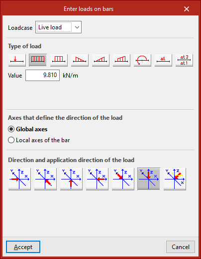
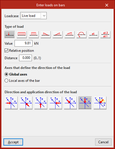
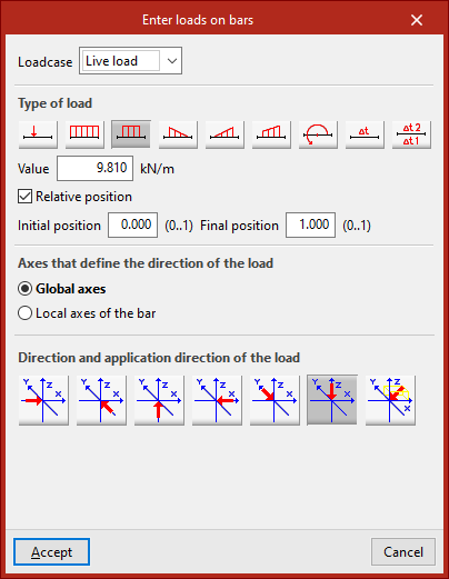
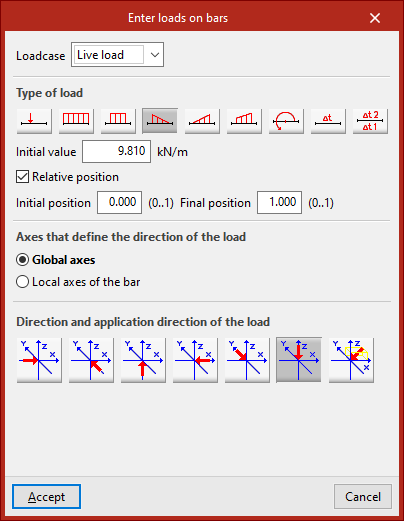
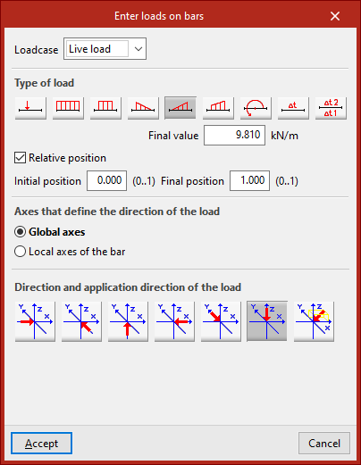
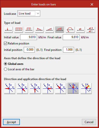
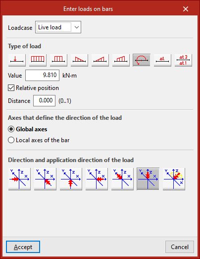
Entering loads on bars
Right-click to open the "Enter loads on bars" window. Here, the "Loadcase" to which the new loads are to be assigned is selected. Then its "Value" is typed in.
Type of load
Among the options available for the "Type of load" are the following:
- Point load
- Uniform load
- Strip load
- Left triangular load
- Right triangular load
- Trapezoidal load
- Applied moment
To place some of these loads on the bar, the program requires a "Distance" to be defined or a "Start position" and an "End position" to be specified in the selected units of measurement. By activating the "Relative position" box, the position of the load can be specified using a value from 0 to 1. A "Uniform load" is applied over the entire length of the bar.
Defining the direction and sense of application of the load
In the central part, the "Axes that define the direction of the load" are specified. These may be the "Global axes" or the "Local axes of the bar".
The "Direction and application direction of the load" is indicated at the bottom. Here you can take the directions of the global axes in both directions or freely define one direction. By default, the program selects the most common case, which is a load in "Direction, according to the Z axis, in the negative direction".
After clicking on "Accept", the program will apply the load on the selected bars.
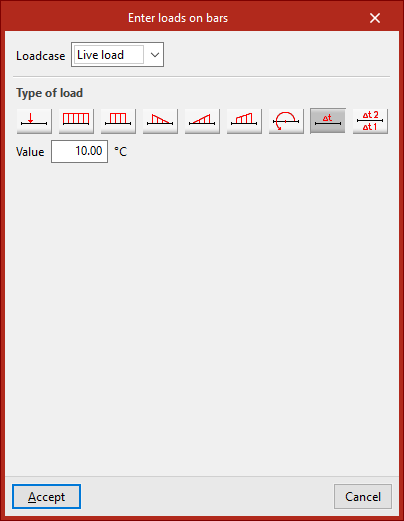
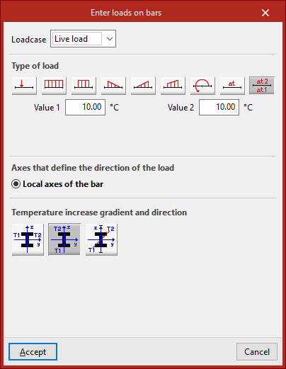
Temperature rise loads
An "Increase in uniform temperature" or an "Increase in variable temperature" between two temperature values can also be entered. In the latter case, the "Temperature increase gradient and direction" is also defined.
The other options in the "Bars" menu are activated when loads on bars have been previously entered:
Edit
The "Edit" option is used to modify the loads on bars that have already been entered.
In the "Properties - Visible loadcase" window that appears, select the "Loadcase" to which the loads to be edited are assigned so that they are visible in the model. The loads are then selected by clicking on them one by one or via a selection window.
By right-clicking, the "Load description" window appears, where the load data can be modified. The same options are offered here that appear when entering the loads. Finally, click on "Accept".
Delete
The "Delete" option is used to remove the selected loads on bars from the model. In the same way, left-click on the loads to select them one by one or use the crossing method to select them all at once and then right-click to delete them.
Loadcase
If only the loadcase of the loads needs to be modified, the "Loadcase" option is used.
To do this, select the loads to be modified and click on the right button.
In the "Loadcase" window, choose the loadcase in the drop-down menu to which the loads will be assigned, and then click on "Accept".
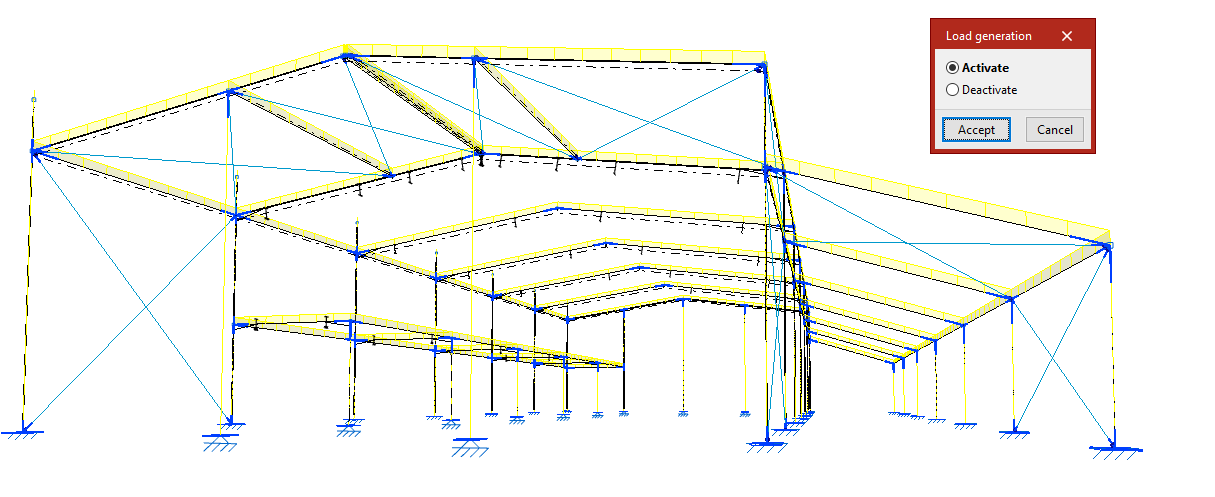
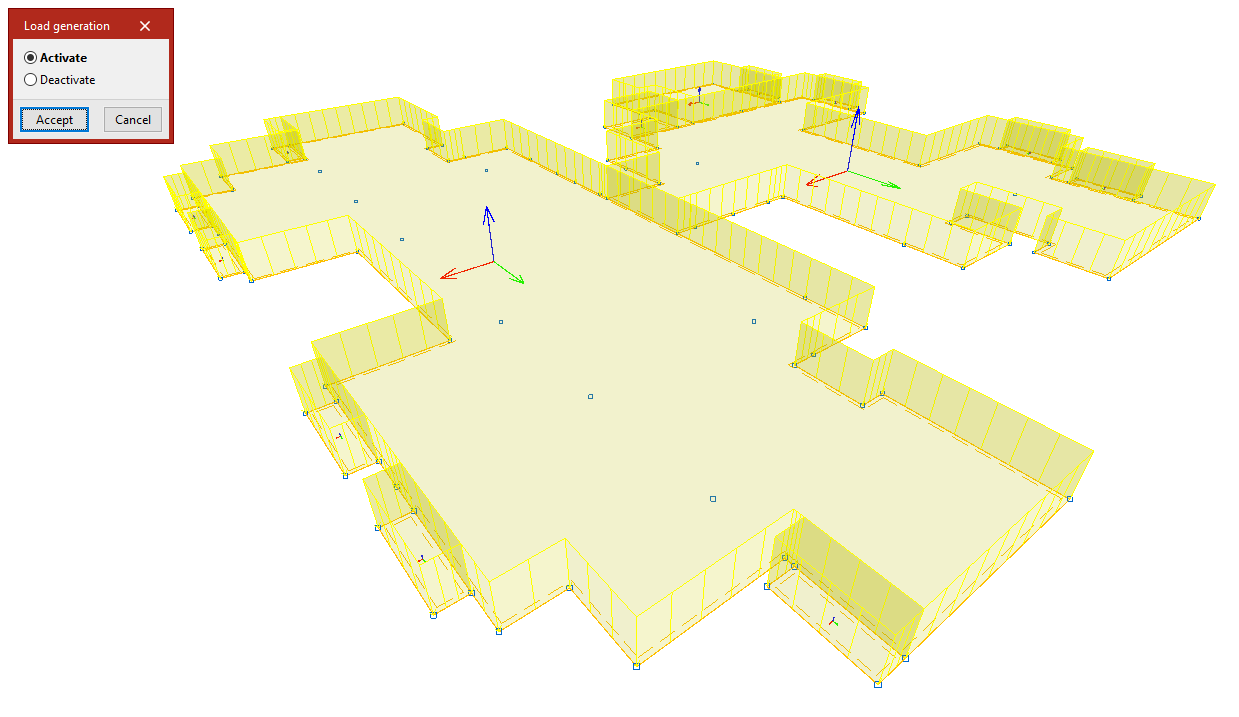
Self weight
The "Self weight" option activates or deactivates the automatic generation of the own weight loads of the bars.
When clicking on it, the "Load generation" dialogue box appears, where you can choose "Activate" or "Deactivate".
By default, the program generates the self-weight loads of the bars and displays them on the screen.
If an action is chosen, the bars must be selected after clicking "Accept". If "Deactivate" is chosen, pressing the right button removes the self-weight loads associated with the selected bars. If "Activate" is chosen, they are regenerated.
Pressing the right button again brings up the "Load generation" box to change the action to be carried out.
Inserting and editing loads on shells
Loads on shells can be entered and edited using the following options, which are available in the "Shells" section of the top toolbar, within the "Load" tab (under the "Structure" tab).

New
The "New" option allows you to enter new loads for a group of shells. Clicking on this option opens the "Properties – Visible loadcase" window, where you can select the "Loadcase" you wish to view. You can also "View all" loadcases by ticking the relevant box.
Next, click on the shells one by one using the left mouse button, or select a capture area.
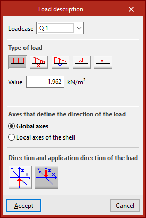
Right-clicking opens the "Enter loads on shells" window. In this window, you must first select the "Loadcase" to which you wish to assign the new loads.
Next, select the "Load type". The options available for "Load type" include the following:
- Uniform load
When selecting this type of load, you must enter its "Value". - Variable load in the local x axis
- Variable load in the local y axis
In the case of variable loads, you must enter both the "Initial value" and the "Final value". - You can also enter a "Increase in uniform temperature" or specify a "Retraction" value.
Surface loads defined in this way are applied across the entire surface of the shell.
The central section specifies the "Axes that define the direction of the load". These may be:
- the "Global axes";
- or the "Local axes of the shell".
The "Direction and application direction of the load" is indicated below. The following may be used:
- "Direction along the Z-axis, in the positive direction";
- or "Direction along the Z-axis, in the negative direction".
Once you click "Accept", the program will apply the load to the selected shells.
The remaining options in the "Shells" section allow you to edit the loads on the shells:
Edit
To edit entries that have already been made, use the "Edit" option.
Select the "Loadcase" to which the loads you wish to edit are assigned, so that they become visible in the model. Then select the loads by clicking on them one by one or by selecting an area.
When you right-click, the "Load description" window appears, where you can edit the load data. The same options are available as when you enter the loads. Finally, click "Accept".
Delete
The "Delete" option allows you to remove loads from selected layers in the model. Left-click on the loads to select them, or draw a selection area and then right-click to remove them.
Loadcase
If you only need to modify the loadcases, use the "Loadcase" option.
Select the items you wish to edit and right-click.
In the "Loadcase" window, select the loadcase to which the loads will be assigned from the drop-down menu, then click "Accept".
Dead weight
The "Self-weight" option enables or disables the automatic generation of self-weight loads for the shells. Clicking on it opens the "Load generation" dialogue box, where you can select "Activate" or "Deactivate".
By default, the program calculates the dead loads for the slabs and displays them on screen.
If you select an action, such as "Deactivate", the shells will be selected after you click "Accept". Right-click to remove the associated self-weight loads. Right-clicking again brings up the "Load generation" dialogue box, allowing you to change the action to be performed.
Applying loads to shells using panels and surface loads
There is another way of applying loads to plates, which involves placing the plate within the area of a load panel. In this case, the panel must be completely covered by shells. Furthermore, the shells pick up any surface loads defined on the panel.
To enter and edit these loads, use the tools available in the "Load" tab relating to panels and surface loads.
Entering and editing load panels
Load panels can be entered and edited using the following options, available in the "Panels" group on the top toolbar, under the "Load" tab (in the "Structure" tab).

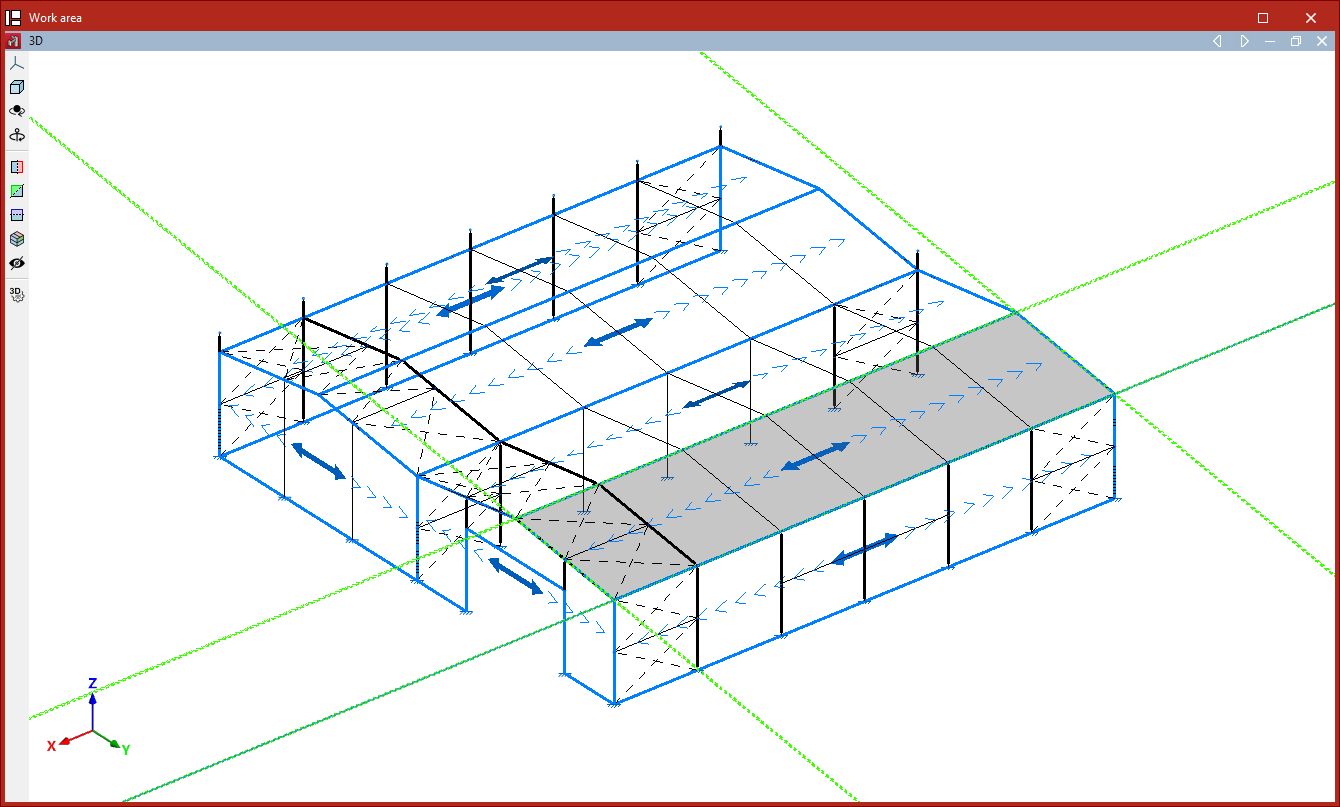
In the program, a panel is a closed polygon that distributes the loads applied to its surface. These loads can either be defined directly when editing the panel, or they can be surface loads whose geometry lies within the panel’s area.
Load distribution is applied to structural elements whose geometry overlaps with that of the panel:
- On the bars located within the panel area and whose direction has a component perpendicular to the distribution direction defined in the panel.
- On the shells whose geometry coincides with or overlaps that of the panel.
The effect is equivalent to entering loads on bars or shells, with the added advantage that the program automatically calculates the value of the load to be applied to each element.
New
To enter panels, select the "New" option.
Defining the panel’s outline
After selecting the option, click with the left mouse button on the points of a closed polygon to define its outline.
Then, right-click to confirm.
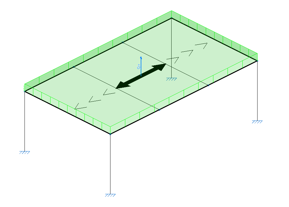
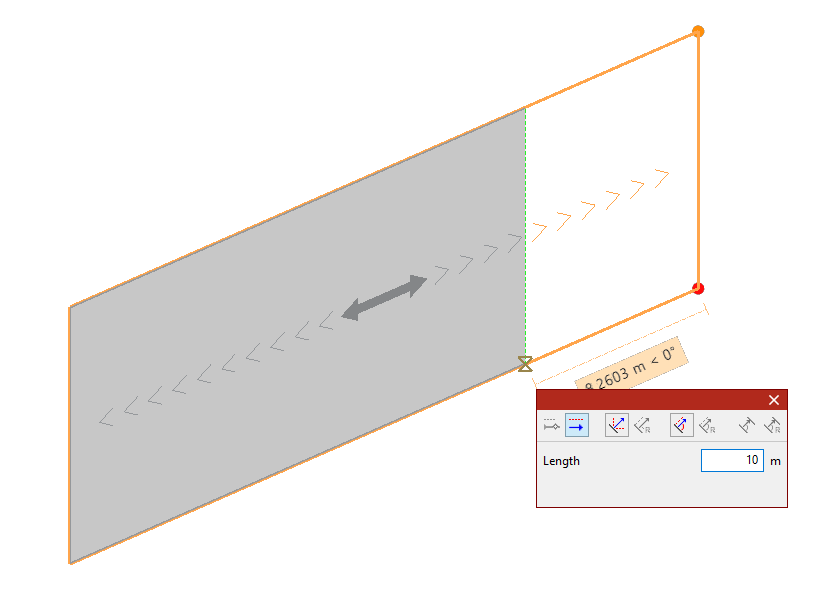
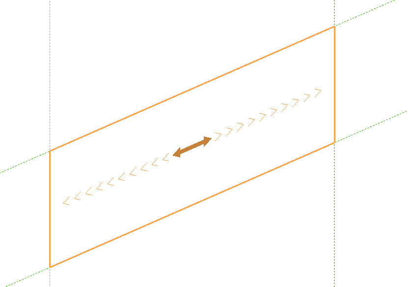
Defining the distribution direction
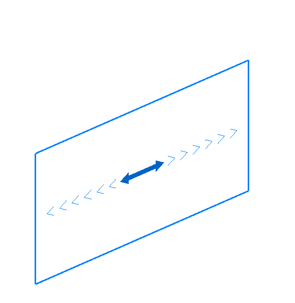
After defining the panel’s outline, you must specify the load distribution direction by left-clicking one of the auxiliary lines located on either side of the panel.
The distribution direction will be "Parallel to the selected side" or "Perpendicular to the selected side", depending on the selection made in the "Load distribution direction" drop-down menu in the "Properties" pop-up window.
| Example: |
|---|
| To create a panel on a roof slope, select its four vertices to define the outline. As the program will apply the load to the bars perpendicular to the distribution direction, if you wish to apply the load to the transverse frames, the distribution direction is that of the chords; therefore, select an auxiliary line parallel to them (by ticking the "Parallel to selected side" option). |
Loads on panel
After defining the panel’s outline and distribution direction, right-click to open the "Loads on panel" window, where one or more loads can be added to the panel under different load cases.
These loads are applied across the entire surface of the panel. If you want to apply loads to only part of the panel, you can leave this table empty and later draw surface loads on the panel’s geometry.
If the panel is not parallel to the global XY plane, two tabs are shown: one for "Uniform" loads and another for loads that "Vary depending on the height". If the panel is horizontal, only the "Uniform" load table is displayed.
Uniform loads
The options at the top allow you to "Add", "Copy", and "Delete" loads. To enter a load, click "Add" and select the "Load case" from the dropdown menu.
Then, check the "Positive direction" of the loads, which is automatically determined based on the selected load case.
Loads associated with wind load cases are applied perpendicular to the panel. In this case, the program shows the coordinates of a unit vector representing the direction of a positive load.
Loads from other load cases are applied vertically along the global Z-axis. By default, the positive direction is "Vertical downwards".
Finally, enter the "Value" of the load, which may be positive or negative depending on the direction of application.
For "Uniform" loads, a single value is defined for the entire surface.
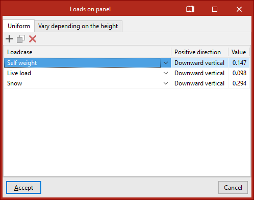
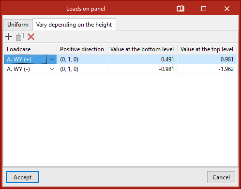
Loads that vary depending on the height
For loads that "Vary depending on the height", in addition to the "Load case" and "Positive direction", you must specify two values: the "Value at the lower level" and the "Value at the upper level" of the panel’s surface.
After clicking "Accept", the program will insert the panel into the model.
Edit
The "Edit" option allows you to edit loads on previously inserted panels.
After selecting the option, choose one or more panels and right-click.
This opens the "Loads on panel" window, where the loads applied to the selected panels can be modified.
| Note: |
|---|
| If multiple panels are selected, the information displayed in the "Loads on panel" window corresponds to the first panel selected; therefore, when confirming, the loads can be matched across all selected panels. |
Delete
The "Delete" option removes the selected panels and their associated surface loads. To do this, select the panels using the left mouse button, and delete by right-clicking.
Move
The "Move" option modifies the geometry of the polygon defining the panel as follows:
- Select the panel using the left mouse button.
- Then click on the vertices of the polygon you want to move.
- Right-click to confirm the selection of these points.
- Left-click to select a reference point for the displacement, and then click on the target point to move the reference.
- Confirm the operation by right-clicking again.
The result is a panel with modified geometry.
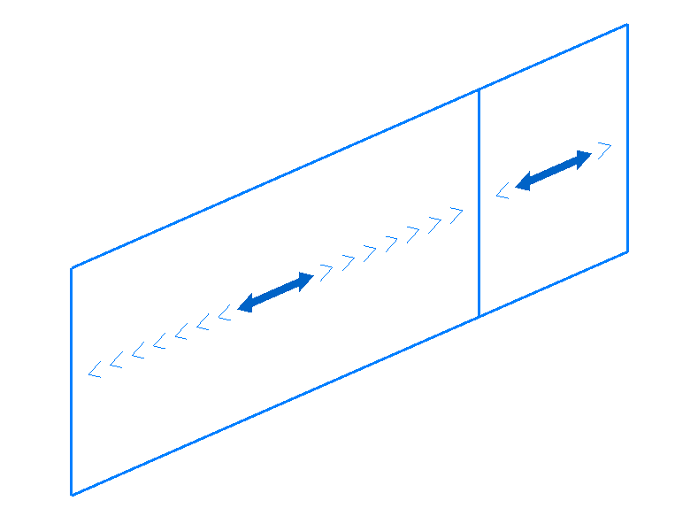
Divide
The "Divide" option allows you to divide a panel by inserting a division line between two points in the work area.
The program will generate two independent panels after the operation.
Distribution direction
The "Distribution direction" option allows you to modify the load distribution direction of a panel using the following steps:
- Select the panel using the left mouse button.
- Indicate the new direction by clicking on one of the auxiliary lines along the sides of the panel (visible when using this option).
The distribution direction will be "Parallel to the selected side" or "Perpendicular to the selected side", depending on the selection made in the "Load distribution direction" drop-down menu in the "Properties" pop-up window.
Entering and editing surface loads
Surface loads can be entered and edited using the following options, available in the "Surface loads" group on the top toolbar, under the "Load" tab (in the "Structure" tab).

Surface loads may occupy all or part of the surface of a load panel, which can be inserted beforehand using the options in the "Panels" group, or alternatively, automatically generated when inserting the surface load. The panel will distribute the surface loads defined on it according to its distribution direction.
The distribution of surface loads is applied to the structural elements whose geometry overlaps with that of the panel:
- To bars that lie within the area of the panel and whose direction has a component perpendicular to the distribution direction defined in the panel.
- To shells whose geometry coincides with or overlaps the panel.
The effect is equivalent to applying loads on bars or shells, with the added benefit that the program automatically calculates the load value to be applied to each element.
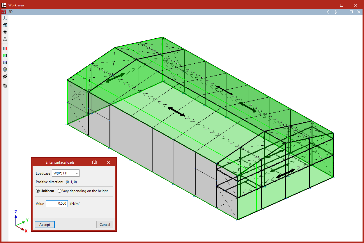
New
The "New" option allows you to insert a new surface load in polygonal form.
To do so, follow these steps:
- Upon selecting the option, the "Visible load case" window appears. Here you can choose the "Load case" to be displayed on screen. You may also "Show all" load cases by ticking the corresponding box.
- Then, use the left mouse button to click the points that form the polygon contour of the surface load.
- Once done, right-click.
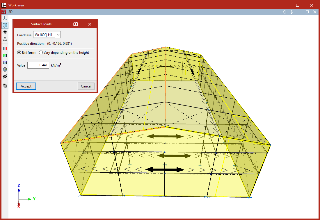
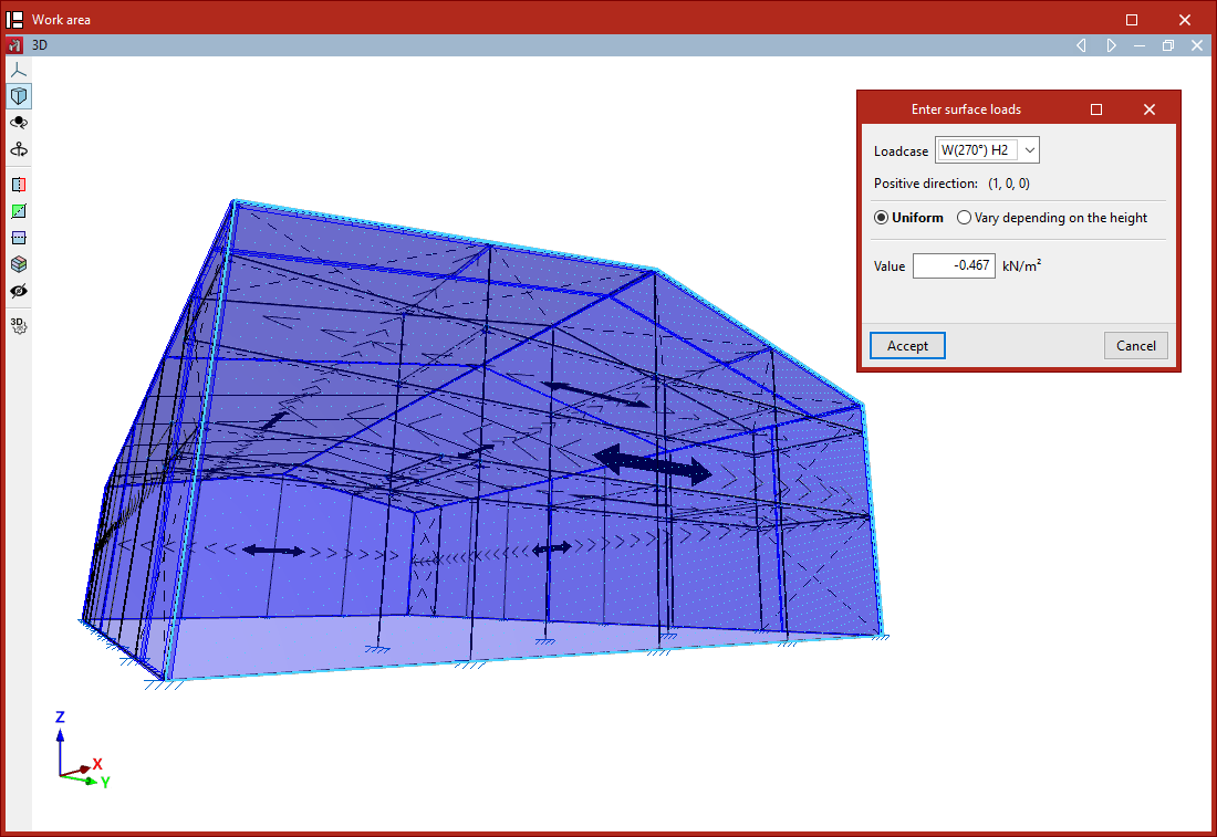
- This opens the "Enter surface loads" window:
- First, select the "Load case" to which the surface load will be assigned.
- The program also displays the "Positive direction" of the load, using the text "Vertical downwards" if the load is not part of a wind load case, or by showing the coordinates of a unit vector in the case of wind loads.
- The load can be either "Uniform" or "Height-varying" if the surface is not horizontal:
- For uniform loads, simply enter the "Value" and its sign.
- For height-varying loads, you must enter both the "Value at the upper level" and the "Value at the lower level". These correspond to the values and signs of the loads at the Z-coordinate of the top and bottom of the loaded surface.
- Finally, click "Accept".
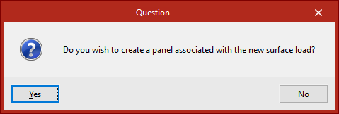
Generating panels associated with surface loads
When a new surface load is inserted, the program checks whether it overlaps with an existing panel. If it does not, the user is asked whether a new panel should be created and associated with the new surface load.
This new panel will have the same shape as the surface load and its distribution direction will be defined by the line joining the first two points of the surface load.
A surface load must belong entirely to a single panel, so a load cannot overlap more than one panel.
| Note: |
|---|
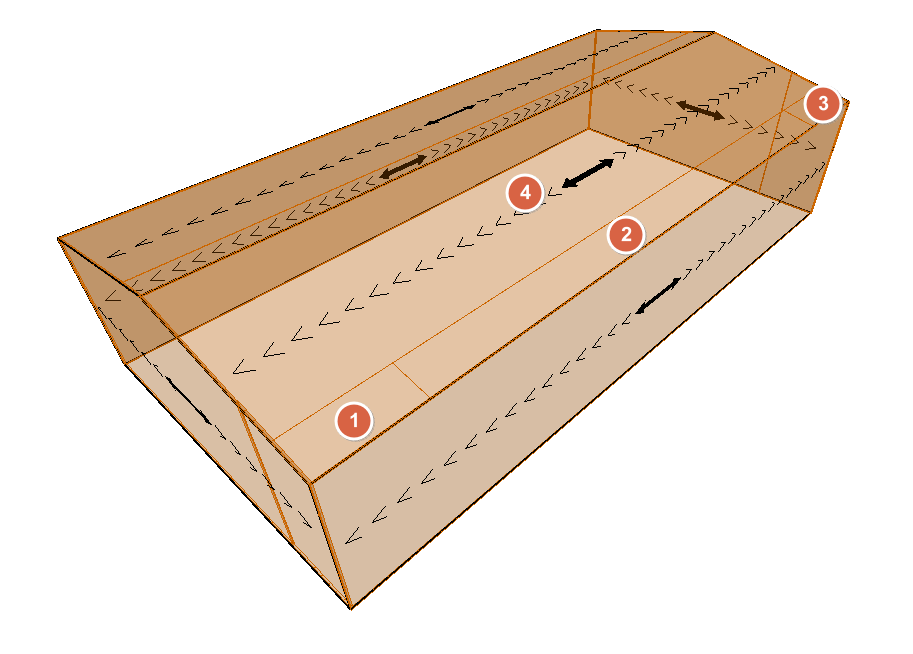
| Multiple surface loads with different geometries and values can be applied on a single panel. One practical example is creating wind pressure zones on a roof slope. |
Edit
The "Edit" option allows you to modify the selected surface loads.
Only the loads associated with the "Visible load case" selected in the pop-up window are displayed.
Then, select the loads to be edited one by one with the left mouse button or by using a selection area, and right-click.The "Surface loads" window appears, where you can modify the load data. The program will apply the changes when you click "Accept".
Delete
The "Delete" option allows you to remove selected surface loads corresponding to the "Visible load case". After selecting the loads one by one or by using a selection area, right-click to delete them.
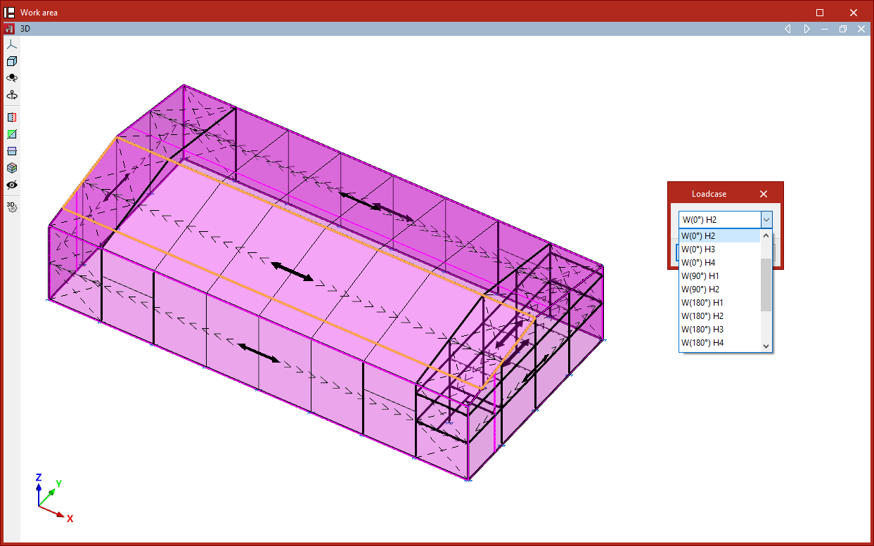
Load case
The "Load case" option allows you to edit the load case assigned to surface loads.
After selecting the loads and right-clicking, choose the "Load case" to assign to the loads.
Copy
The "Copy" option creates a new surface load by duplicating an existing one.
After selecting this option, choose a surface load. The "Enter surface loads" window will appear, where you can specify the "Load case", type, and values of the new surface load.
This new load will have the same shape and position as the existing one and will be generated in the same location.
| Note: |
|---|
| This option is useful for quickly creating loads of different load cases and values on the same surface (e.g. a façade or a roof slope). |
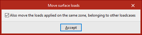
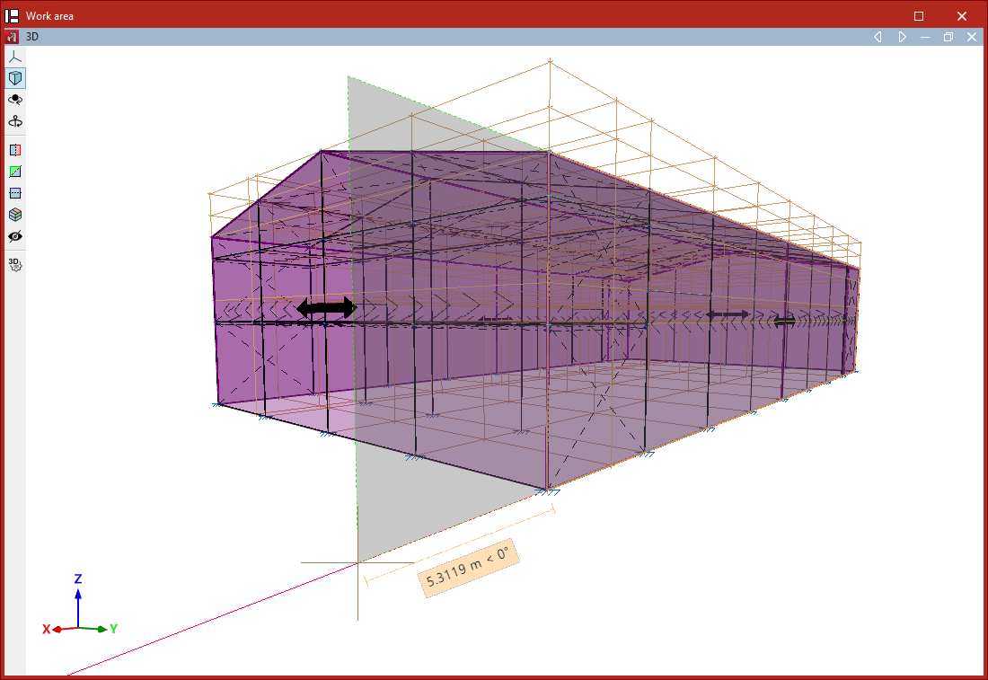
Move
The "Move" option allows you to change the shape and/or position of the polygon that defines a surface load.
- When selecting the option, the "Visible load case" window appears. You can choose the "Load case" to display or "Show all" by ticking the appropriate box.
- Before continuing, right-click to access a dialogue where you can indicate whether to "Also move the loads applied on the same zone, belonging to other loadcases" by checking or unchecking the corresponding box.
- After clicking "Accept", first select the surface load you wish to modify with the left mouse button.
- Then, also with the left mouse button, select the vertices of the polygon you wish to move.
- Right-click to confirm the point selection.
- Now, left-click to select a reference point for the displacement, then click the destination point to which you wish to move the selected reference point.
- Finally, right-click again to confirm.
The result is a surface load with modified geometry.
Assign
The "Assign" option allows you to enable or disable the assignment of surface loads to bars, meaning you can specify whether certain bars are to receive loads from panels or surface loads.
Select the bars to be enabled or disabled one by one with the left mouse button, or use a selection area. Then, right-click.
Disabled bars are displayed as dashed lines, while enabled bars are shown with solid lines. By default, all bars (except ties) are enabled.
If a bar is disabled, it cannot receive surface loads in any load case. This option does not apply to bars defined as ties, as ties cannot receive loads.
Table of contents
Complete your CYPE 3D journey by exploring the other available sections:
- Introduction
- Start: creating new projects, workflows, and examples
- Setting the work environment
- Setting the job data
- Defining the structure’s geometry
- Editing the properties of structural elements
- Entering and editing loads on the structure
- Designing and analysing connections
- Analyses, checks, and results
- Defining and editing reinforcement
- Designing and analysing foundation
- Printing documents and exporting data